1
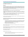
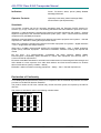
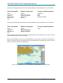
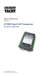
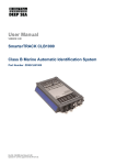
OPERATION & INSTALLATION MANUAL AIS-CTRX Class B AIS Transponder Version 1.0E © True Heading 2006 The manual may not in any aspect be copied without the prior authorization from True Heading AB. AIS-CTRX Class B AIS Transponder Manual TABLE OF CONTENTS TABLE OF CONTENTS.............................................................................................. 2 REVISION .................................................................................................................. 5 INTRODUCTION ........................................................................................................ 6 GLOSSARY................................................................................................................ 7 CONDITIONS ............................................................................................................. 9 WARRANTY ............................................................................................................. 10 General.................................................................................................................. 10 Warranty conditions ............................................................................................... 10 Warranty procedures ............................................................................................. 10 Other issues .......................................................................................................... 10 SUPPORT ................................................................................................................ 11 GENERAL NOTICE.................................................................................................. 12 LICENSING .............................................................................................................. 13 INFORMATION ABOUT AIS .................................................................................... 14 General.................................................................................................................. 14 Short technical description of AIS.......................................................................... 15 Limitations with AIS ............................................................................................... 16 PRODUCT SPECIFICATION ................................................................................... 17 Declaration of Conformity ...................................................................................... 18 INSTALLING THE AIS-CTRX UNIT ......................................................................... 19 Electrical Connections ........................................................................................... 19 Physical Mounting ................................................................................................. 20 PROGRAMMING THE TRANSPONDER ................................................................. 21 P1.0E 2 LD2103 AIS-CTRX Class B AIS Transponder Manual Field Programmer.................................................................................................. 21 USING THE TRANSPONDER.................................................................................. 22 Switching on .......................................................................................................... 22 Warning and Fault States ...................................................................................... 22 Data Port Messages .............................................................................................. 22 Information Transmitted and Received .................................................................. 23 Built in Test............................................................................................................ 23 LED Indicators ....................................................................................................... 23 Antennas ............................................................................................................... 24 MAINTENANCE ....................................................................................................... 25 SERIAL DATA INTERFACE ..................................................................................... 26 Power Connection / Data Connection.................................................................... 26 Serial Port Input/Output ......................................................................................... 26 Power Up Messages ............................................................................................. 26 VHF Data Link Messages (NMEA 0183 VDM) ...................................................... 26 VHF data link own vessel messages (NMEA 0183 VDO)...................................... 28 Regional Assignment Channel Assignment Message (NMEA 0183 ACA) ............ 28 Channel management information source messages (NMEA 0183 ACS)............. 29 AIS Alarm Messages (NMEA 0183 ALR, Text)...................................................... 29 ACK messages...................................................................................................... 30 ANTENNA CONNECTIONS ..................................................................................... 31 GPS Antenna......................................................................................................... 31 VHF antenna ......................................................................................................... 31 Antenna Types and Mounting................................................................................ 31 OPERATIONAL GUIDELINES FOR AIS-CTRX ....................................................... 32 FAQ .......................................................................................................................... 35 P1.0E 3 LD2103 AIS-CTRX Class B AIS Transponder Manual NOTES ..................................................................................................................... 38 DRAWINGS.............................................................................................................. 39 Packing List ........................................................................................................... 39 Fixing Template (NOT TO SCALE) ....................................................................... 39 General Arrangement ............................................................................................ 41 Cable Assemblies.................................................................................................. 41 APPENDIX A ANTENNAS AND ANTENNA MOUNTING ...................................... 43 GPS Antenna......................................................................................................... 43 VHF antenna for AIS use....................................................................................... 43 WARNINGS........................................................................................................... 43 P1.0E 4 LD2103 AIS-CTRX Class B AIS Transponder Manual REVISION Version Date Responsible Approved Changes P1.0E 2006-11-22 Anders Bergström Nils Willart Preliminary release 1.0E 2006-11-23 Anders Bergström Nils Willart First release P1.0E 5 LD2103 AIS-CTRX Class B AIS Transponder Manual INTRODUCTION We would like to thank you for choosing True Heading AB as supplier of your AIS-CTRX, AIS Class B Transponder. The AIS-CTRX is a high quality AIS Class B Transponder using the latest technology. AIS-CTRX makes it possible to receive information from ships, buoys, lighthouses, SAR helicopters, Coastguard units, Pilot boats, Weather station etc. and to send information about your own ship to others that are equipped with Automatic Identification System (AIS) transponders or receivers. SEE AND BE SEEN It is today, according to the IMO SOLAS regulation a requirement for all ships above 300 GT to carry AIS. This means that a large number of ships and other types of navigational information providers will be seen by your AIS-CTRX and contribute to enhanced safety in your navigation. Picture 1 Real traffic scenario between Sweden and Bornholm (Denmark) It is of utmost importance that you read this manual before you start to install and use your AIS-CTRX. P1.0E 6 LD2103 AIS-CTRX Class B AIS Transponder Manual GLOSSARY ACA (AIS) Regional Assignment Channel Assignment Message ACK Acknowledgement ACS (AIS) Channel management information source messages AFSK Audio frequency-shift keying ALR (AIS) Alarm Message A to N Aid to Navigation AIS Automatic Identification System ATC Air Traffic Control BIIT Built In Integrity Testing BNC Bayonet fitting type RF connector CSTDMA Carrier Sense Time Division Multiple Access COG Course over Ground CR Carriage Return CS Carrier Sense CSTDMA Carrier Sense TDMA DC Direct Current DGNSS Differential Global Navigation Satellite System DGPS Differential Global Positioning System DSC Digital Selective calling ETA Estimated Time of Arrival GALILEO European equivalent to GPS GLONASS Global Navigation Satellite System GNSS Global Navigation Satellite System GMSK Gaussian Minimum Shift Keying GPS Global Positioning Satellite / System HF High Frequency IMO International Maritime Organization IEC International Electrotechnical Commission LED Light Emitting Diode LF Line Feed LNA Low-noise amplifier MF Medium Frequency MKD Minimum Keypad and Display MMSI Maritime Mobile Service Identity MPE Maximum Permissible Exposure NM Nautical Mile = 1852 m NMEA National Marine Electronics Association PC Personal Computer P1.0E 7 LD2103 AIS-CTRX Class B AIS Transponder Manual PI Presentation Interface RF Radio Frequency RTCM Radio Technical Commission for Maritime Services Commission RX Receive or Receiver RFI Radio frequency interference SAR Specific Absorption Rate SELV Separated Extra Low Voltage SMA Swedish Maritime Administration SMS Short Message System SOG Speed over Ground SOLAS Safety Of Life At Sea SOTDMA Self Organized Time Division Multiple Access. SRM Safety Related Message SRT Software Radio Technology TDMA Time-division Multiple Access TNC Threaded type BNC connector TX Transmit or transmitter UTC Universal Time Co-ordinated VDM (AIS) VHF Data Link Messages VDO (AIS) VHF data link own vessel messages VHF Very High Frequency VTS Vessel Traffic Services (Like ATC but for ships) VSWR Voltage Standing Wave Ratio P1.0E 8 LD2103 AIS-CTRX Class B AIS Transponder Manual CONDITIONS Before you start using the AIS-CTRX product from True Heading AB it is important that you read and fully understand the installation manual and its instructions. You should only proceed with the installation if you are confident that you will be able to do so. True Heading AB cannot be held liable for any injury or damage caused by, during or because of the installation of AIS-CTRX. The AIS-CTRX is used at your own risk and it shall be remembered that AIS and GPS data depends on the full co-operation of other users and systems. AIS-CTRX is a navigation aid and works in co-operation with other similar systems like e.g. radar, optical lookout etc. The AIS-CTRX installation should be inspected from time to time and checked on its operational quality frequently by the user. Remember that navigation and life at sea always requires proper seamanship and that the AIS-CTRX is not a replacement for such qualities. NOT ALL VESSELS CARRY AIS. IT IS THEREFORE IMPORTANT TO KEEP PROPER LOOKOUT AT ALL TIMES AND TO USE ALL AVAILABLE MEANS TO AVOID COLLISIONS AND ACCIDENTS. GPS MAY FROM TIME TO TIME INCLUDE ERRORS: THEREFORE, THE POSITION RECEIVED FROM THE GPS BUILT IN TO AIS-CTRX SHALL ALWAYS BE VERIFED WITH OTHER AVAILABLE MEANS. P1.0E 9 LD2103 AIS-CTRX Class B AIS Transponder Manual WARRANTY General AIS-CTRX is developed and manufactured to meet high technical requirements and user demands. If installed correctly and with regular maintenance your AIS-CTRX should provide you with several years of operation and a very useful product. For further information provided in the manual and in this information sheet please consult the place where you purchased the AIS-CTRX or direct to our support. Warranty conditions - The warranty belongs to the person that purchased the product and cannot be handed over to a third party or person. - The warranty is not valid if serial number is missing, seals broken or if the AIS-CTRX has been incorrect installed. Neither is the warranty valid if instructions for connection have not been followed, faults caused by wrong usage, own made modifications or service made from none authorized service stations. - True Heading AB acknowledges that AIS-CTRX at delivery has been controlled and found operational. - True Heading AB agrees to repair or replace any faulty unit without any cost according to the conditions set forth during a period of two (2) years from day of purchase. - The warranty includes replacement or repair of faulty unit due to error in components or errors in relation to the production of the product. - The warranty covers costs for spares, labor, and return shipment. It does not include shipment from to the repair facility. - True Heading AB will never be liable under the warranty conditions for incorrect use, misuse, and incidental, indirect or consequential damages of the AIS-CTRX. - Proof of purchase is required for any warranty claim of the AIS-CTRX. Warranty procedures True Heading AB repairs and replaces faulty parts or units. The customer is responsible for transport of the defect part or unit to True Heading or its retailer. Warranty claims shall be made to the place where AIS-CTRX was purchased or direct to True Heading AB through mail, fax or e-mail to our support department. Other issues Proper seamanship and common sense is applicable when using AIS-CTRX and the products shall only be seen as a navaid. True Heading AB keeps the right to change the specification of the product without prior notice. IF YOU ARE NOT ABLE TO ACCEPT THE TERMS ABOVE, PLEASE RETURN THE AIS-CTRX TO YOUR RETAILER FOR FULL CREDIT BEFORE OPENED AND USED. P1.0E 10 LD2103 AIS-CTRX Class B AIS Transponder Manual SUPPORT If you need support, please contact the closest reseller or the location where you acquired the product. The manufacturer can also give support direct: Email: [email protected] or Fax: +46 8 6618020. Please register your purchase of AIS-CTRX with True Heading AB by sending an e-mail to [email protected] stating the serial number, date of purchase, your name, address and your dealer’s name. P1.0E 11 LD2103 AIS-CTRX Class B AIS Transponder Manual GENERAL NOTICE The Automatic Identification System (AIS) unit mostly utilise a Global Navigation Satellite System (GNSS) system such as e.g. GPS or GLONASS to determine position. The accuracy of these systems is variable and can be affected by factors such as the positioning of the antenna, the number of satellites available to determine a position and for how long satellite information has been received. It is desirable as often as possible to verify both your vessel’s AIS derived position data and other vessels AIS derived position data with visual or radar based observations. The compass safe distance of this unit is 0.5m or greater for 0.3° deviation. P1.0E 12 LD2103 AIS-CTRX Class B AIS Transponder Manual LICENSING IMPORTANT: In most countries the operation of an AIS unit is included under the vessels marine VHF radio licence provisions. The vessel on to which the AIS unit is to be installed must therefore possess a valid VHF radiotelephone licence which lists the AIS system and the vessel Call Sign and MMSI number. Please contact the relevant authority in your country for more information. In accordance with our policy of continuous development and product improvement the AIS-CTRX hardware and/or software may be upgraded from time to time and future versions of the AIS-CTRX may therefore not correspond exactly with this manual. When necessary upgrades to the product are made, these will be accompanied by updates or addenda to this manual. Please take time to read this manual carefully to understand its contents fully so that you can install and operate your AIS system correctly. Information contained in this manual is liable to change without notice. True Heading AB disclaims any liability for consequences arising from omissions or inaccuracies in this manual and any other documentation provided with this product. © 2006 True Heading AB P1.0E 13 LD2103 AIS-CTRX Class B AIS Transponder Manual INFORMATION ABOUT AIS General AIS (Automatic Identification System) is the name of a system that makes it possible for ships to identify other ships and to monitor ship movements. The reason for implementing the AIS system is for the mariner to obtain more information about ships in the vicinity than what radar is able to provide. AIS gives e.g. information about a ships identity (name, call sign, IMO number and MMSI), size this even for ships behind Island or bends that radar cannot detect. AIS is used to enhance safety for life at sea, improve safety and efficiency in navigation and protect the marine environment. AIS-information transmitted from a ship contains of three (3) different main types: - Static data that was programmed into the AIS equipment at installation and it only needs to be changed if the ship changes its name, flag or undergoes a major refit where size or ship type is changed; - Dynamic data contains information that automatically is updated from ship sensors like the heading from the Gyro, Position and speed from GNSS equipment. Also navigational status belongs to the group of dynamic data but is updated manually by the crew; and - Voyage related data that manually is updated by the crew along the voyage. From the start AIS some times also was referred to as UAIS or as the 4S transponder system that meant Ship to Ship and Ship to Shore. IMO adopted 1998 a performance standard for AIS within the SOLAS requirement that described in general how AIS should work. Below follows a brief description of the main requirements for AIS from the performance standard: • • • • Automatically provide information to AIS land stations, other ships and airborne units e.g. SAR helicopters about the ships identity, Type of ship, Position, Course, Speed, Navigational status (e.g. under way using engine, at anchor) and other safety related information of importance. Be able to receive the same type of information from other ships. Be able to monitor and track other ships. Exchange information with land based AIS systems. AIS is an automatic system that continuously and simultaneously transmits on two channels in the maritime VHF frequency band. AIS can handle several reports in a rapid consecutive flow. To accomplish these AIS uses a technique called Self Organized Time Division Multiple Access (SOTDMA) that guarantees high transmission safety and operational robustness. AIS also allows for other types of information from e.g. sensors like Gyro, GPS and echo sounders etc. to be transmitted automatically. Important areas where AIS is used are: • P1.0E Information exchange between ships within VHF range (normally 20-30 NM) to enhance safety at sea and to improve situation awareness. 14 LD2103 AIS-CTRX Class B AIS Transponder Manual • Information exchange between ships and AIS land stations as e.g. a VTS that controls and monitors maritime traffic in an area. • Automatic reporting in areas with mandatory reporting of different kinds. • Exchange of safety related information between ships and between ships and land stations. • Services like e.g. meteorological information in real-time from areas of importance, identity and position of floating and fixed aids to navigation to improve identification and navigation. How AIS Works The marine Automatic Identification System (AIS) is a location and vessel information reporting system. It allows vessels equipped with AIS to automatically and dynamically share and regularly update their position, speed, course and other information such as vessel identity with similarly equipped craft. Position is derived from a Global Navigation Satellite System (GNSS) network and communication between vessels is by Very High Frequency (VHF) digital transmissions. A sophisticated and automatic method of time sharing the radio channel is used to ensure that even where a large number of vessels are in one location blocking of individual transmissions is minimised, any degradation of the expected position reporting interval is indicated to the user and even if the unit suffers extreme channel overload conditions it will always recover to normal operation. AIS Classes There are two classes of AIS unit fitted to vessels, Class A and Class B. In addition AIS base stations may be employed by the Coastguard, port authorities and other authorised bodies. AIS units acting as aids to navigation (A to N) can also be fitted to fixed and floating navigation markers such as channel markers and buoys. Class A units are a mandatory fit under the safety of life at sea (SOLAS) convention to vessels above 300 gross tons or which carry more than 11 passengers in International waters. Many other commercial vessels and some leisure craft also fit Class A units. Class B units are currently not a mandatory fit but authorities in several parts of the world are considering this. Class B units are designed for fitting in vessels which do not fall into the mandatory Class A fit category. The AIS-CTRX is a Class B unit Position Information Source As noted above the marine AIS system uses position information derived from networks such as the Global Positioning Satellite (GPS) or the Global Navigation Satellite System (GLONASS) in order to determine the location of the AIS unit and thus the vessel to which it is fitted. Short technical description of AIS s, depending on the speed and AIS operates primarily on two dedicated VHF-frequencies (AIS1 – 161,975 MHz and AIS2 – 162,025 MHz). In areas where these two channels are not available, AIS can automatically change to other alternatively available frequencies. AIS uses two VHF radio channels, where the information is transmitted in short data packages or slots in predefined and synchronized time frames. The dynamic information (position, speed, heading etc) is transmitted in intervals from 2 s up to 10 maneuvers of the transmitting ship were the AIS is mounted. Static and voyage related information (type of ship, size, cargo, destination etc.) is P1.0E 15 LD2103 AIS-CTRX Class B AIS Transponder Manual transmitted every sixth minute or upon request from other units. Position, course and speed normally are collected from the same sensor systems that provides the same information used in the navigation e.g. in radars or ECDIS and this is normally based on GPS or DGPS. All ships within VHF coverage will be able to receive AIS data and competent authorities that have installed networks with coastal AIS coverage can receive the information. The capacity for the ships to report is defined by the IMO performance standard to a minimum of 2000 data packages or slots per minute (see picture 2). ITU (Technical Standard for the Universal AIS) has been kind to double this and has provided AIS with 4500 data packages or slots per minute. The transmission is based on the (SO)TDMA (Self-organized Time Division Multiple Access) technique, that allows the system to overload with 400 till 500 % and still give almost a 100 % message throughput between ships that are closer to each other than 8 to 20 nautical miles. In such case the system overloads targets far away will be discriminated in favor of targets close to your own ship. In reality, the system capacity is unlimited and allows for a large number of ships to communicate simultaneously. Picture 2 The principle of AIS technology on the two radio channels. Limitations with AIS You should always be aware that all ship others ships and in particular pleasurecrafts, fishing boats, warships and some coastal stations and VTS centers not will be equipped with AIS. Ships that have been mandated to carry AIS can also under certain conditions turn of there AIS equipment at the master’s disgrace. Therefore it is important to be aware that the information that AIS provides might not be the full and complete picture of the situation around your ship. Users of AIS must also be aware that transmission of false data can occur and that this will be hazardous not only to your own ship but to other as well. The user is responsible for all data that is entered into the system and for information provided by external sensors. The accuracy of received AIS data is only as good as the information transmitted from the source of information. You should always be aware that wrong configured or calibrated ship sensors (positions-, speed- or heading sensors) could lead to that wrong information will be transmitted. Dangerous situations can occur if faulty information is shown on another ship. P1.0E 16 LD2103 AIS-CTRX Class B AIS Transponder Manual PRODUCT SPECIFICATION Dimensions: 190 x 135 x 83 mm (L x W x H) Weight: 1,45 kg Power: DC (9.6-15.6V) Average power consumption 4W Peak current rating 2A GPS Receiver (AIS Internal): IEC 61108-1 compliant Electrical Interfaces: RS232 38.4kBaud bi-directional RS422 NMEA 38.4kBaud bi-directional Connectors: VHF Antenna connector GPS Antenna connector RS232/RS422/Power VHF Transceiver: 1 Transmitter, 2 Receivers (One receiver time shared between AIS and DSC) Frequency: 156.025 to 162.025 MHz Output Power: 33dBm ± 1.5 dB Channel Bandwidth: 25 kHz Channel Step: 25 kHz Modulation Modes: 25 kHz GMSK (AIS, TX and RX) 25 kHz AFSK (DSC, RX only) Bit rate: 9600 b/s ± 50 ppm (GMSK) 1200 b/s ± 30 ppm (FSK) RX Sensitivity: -107dBm 25 kHz (Message Error Rate 20%) Co-Channel 10dB Adjacent Channel 70dB IMD 65dB Blocking 84dB Environmental: IEC 60945, Operating Temperature: -25ºC to +55ºC IEC 62287, Section 5, Cat c) exposed to the weather P1.0E 17 LD2103 AIS-CTRX Class B AIS Transponder Manual Indicators: Power, TX timeout, status, pre-set (Safety Related Message) SRM sent. Operator Controls: Optional pre-set safety related message SRM) transmit button (Not implemented) Standards This product complies with all the necessary standards under the European R&TTE directive for Article 3.1(a), 3.1(b), 3.2 and 3.3(e). The following standards have been followed in pursuance of this: IEC62287-1: 2006-03 Maritime navigation and radiocommunication equipment and systems – Class B shipborne equipment of the automatic identification system (AIS) – Part 1: Carrier-sense time division multiple access (CSTDMA) techniques IEC60945: 2002-08 Maritime navigation and radiocommunication equipment and systems – General requirements – Methods of testing and required test results IEC61162-1: Maritime navigation and radiocommunication equipment and systems – Digital interfaces – Part 1: Single talker and multiple listeners IEC61108-1: GLOBAL NAVIGATION SATELLITE SYSTEMS (GNSS) – Part 1: Global positioning system (GPS) -Receiver equipment - Performance standards, methods of testing and required test results EN 301 843-1 v2.1: Electromagnetic compatibility and Radio spectrum Matters (ERM); Electromagnetic Compatibility (EMC) standard for marine radio equipment and services; Part 1: Common technical requirements EN 50383: 2002 Basic standard for calculation and measurement of electromagnetic field strength and SAR related to human exposure from radio base stations and fixed terminal stations for wireless telecommunications system (110MHz – 40GHz) EN60950-1:2002 Information technology equipment – Safety – Part 1: General requirements Declaration of Conformity True Heading AB declares that this product is in compliance with the essential requirements and other provisions of the R&TTE directive 1995/5/EC. The product carries the CE mark, notified body number and alert symbol as required by the R&TTE directive The product is intended for sale in the following member states: P1.0E 18 LD2103 AIS-CTRX Class B AIS Transponder Manual INSTALLING THE AIS-CTRX UNIT WARNING: Do not connect the AIS-CTRX unit to mains (line) AC electrical supply, as an electric shock or fire hazard could result. CAUTION: Do not connect the AIS-CTRX unit to a DC supply exceeding 15.6 V or reverse the supply polarity. Damage to the unit may result. CAUTION: The AIS-CTRX unit is designed for operation in the temperature range -25 °C to +55 °C. Do not install (or use) the AIS-CTRX unit in environments which exceed this range. CAUTION: do not install the AIS-CTRX unit in an environment where it can be subject to excessive exposure to water. Electrical Connections Warning: Only the RF, data and power cables provided with the AISCTRX unit should be used to connect antennas, power and display devices so as to maintain the integrity of the enclosure. Please see the drawings section of this manual for details of the power, data and RF cables supplied GPS Antenna Cable Remove the top transponder unit screws) as shown. VHF Antenna Cable of the (eight Using the two co-axial leads supplied connect the downlead from a VHF antenna to the VHF antenna port and connect the down-lead of a GPS antenna to the GPS antenna port. Please see Appendix A for recommendations on antennas and antenna installation. Power Cable (or Power and Data Cable) If an external display unit (chart plotter, PC etc) is to be used connect the supplied power and data interface cable to the Power / NMEA port. If an external display unit is not to be used connect the supplied power only interface cable to the Power / NMEA port. Locate the RF, power and/or data cables into the rubber grommets pushing them firmly to the base of each slit. Each cable is pushed into the grommet slit which lies directly in front of the connector the cable is connected to. Replace the top of the transponder unit taking care to seat the cable grommets and the lid seal correctly. Do not over-tighten the fixing screws. P1.0E 19 LD2103 AIS-CTRX Class B AIS Transponder Manual If an external display unit is to be used (such as a chart plotter, PC serial terminal or other display device) connect the user end of the data interface cable to the display device. Note that the software in the display device must be configured for AIS operation AND to accept standard Class B operation NMEA sentences. This external display unit software is not part of the AIS-CTRX transponder package. Connect a 12V DC supply (9.6-15.6V) capable of supplying 2A peak to the DC power lead (brown/red = positive, black/blue=negative). It is recommended that the supply voltage be SELV in accordance with EN 60950-1. The case of the unit is not isolated from the negative terminal of the supply and therefore it is recommended that the unit is not attached to metal parts of the vessel. Physical Mounting It is recommended that the unit is attached to a solid wooden surface with 20mm M3 self tapping screws. A template for drilling pilot holes is shown on page 39. P1.0E 20 LD2103 AIS-CTRX Class B AIS Transponder Manual PROGRAMMING THE TRANSPONDER Field Programmer Before the AIS-CTRX can be used it requires ‘personalisation’. This is done via the AIS-CTRX field programmer package which is supplied as an accessory. This software is designed to be installed on a PC and to use the data lead provided as standard with the AIS-CTRX unit. If the PC being used for programming does not have a 9-pin serial port then a commercially available USB to serial adaptor may be required. This connects between the supplied data lead and the PC. The Field Programmer software has password controlled access with three levels: Operator, Dealer and Engineer. Using the operator function only allows reading of unit information. Using the Dealer function allows editing of unit data, and using the Engineer function provides all the access of the Dealer function with the additional feature of allowing upgrading of embedded software. The programming process operates as follows: • A data record is created for an individual AIS-CTRX. • If required this data record is then edited. • The data record is saved to a data base. • The AIS-CTRX unit is then programmed. • If required the programming can then be checked by ‘reading’ the AIS-CTRX. The AIS-CTRX personalisation data required is the ship’s MMSI, the ship’s name, its dimensions, position reference, type and call sign. The Date Entry function is accessible via the dealer and engineer passwords and personalisation data can be created as follows: Direct Entry By entering the ship’s MMSI, the ship’s name, its dimensions, position reference, type and call sign directly into the programming software. Read Existing Data By reading an already programmed MMSI, ship’s name, its dimensions, position reference, type and call sign. Read Database By reading from a previously created record in the data base the ship’s MMSI, the ship’s name, its dimensions, position reference, type and call sign. Other features: Help There is a context based Help file which explains what each data entry field means and what sort of data is expected. Help is accessible via the dealer and engineer passwords. Print The programmer will print out the information ‘Read’ from or ‘Written’ to an AIS-CTRX Class B unit. P1.0E 21 LD2103 AIS-CTRX Class B AIS Transponder Manual USING THE TRANSPONDER Switching on When the 12V supply is switched on all four LEDs visible on the front panel of the unit will illuminate twice for a period of one second on each illumination. The red and blue LEDs will then go out. When the internal GPS starts outputting valid position information and the AIS-CTRX unit transmits its first position report (message 18) the yellow LED will go out; Note that this process may take up to 30 minutes depending on the switch-on state of the GPS receiver. When the yellow LED goes out the green LED will illuminate indicating that the unit is now operating correctly. SRM SAFETY RELATED MESSAGE Green (Unit operating OK) Yellow (Warning) Red (Fault) Blue (SRM) Warning and Fault States If the unit has not been able to transmit a position report during the last expected two reporting intervals (i.e. the nominal reporting interval cannot be maintained for operational reasons such as a Message 23 quiet period, high channel load conditions, etc) the yellow LED will illuminate. This is a warning condition only and indicates that your vessels position is not currently being reported to other vessels. Reception of other vessel AIS information by the AIS-CTRX is not affected. When the unit is able to commence reporting the yellow LED goes out. If a fault occurs the red LED will illuminate. This may illuminate briefly if the power supply is interrupted or if the characteristics of the VHF antenna are briefly affected. If the Red LED illuminates continuously the unit should be assumed to be faulty and should either be switched off (power removed) or if this is not practical any other vessel position information derived from the unit should not be used and it should also be assumed that the unit is not transmitting valid position information for your vessel. The unit should be examined by a competent equipment maintainer at the earliest opportunity. More details on LED indications can be found in the Operation section of this manual. Data Port Messages The data port will output the following: • (At power-up) boot-loader and main application splash text screens including version numbers, and memory status • Details of relevant AIS transmissions received • Details of AIS transmissions sent • Details of channel management messages received • Alarm messages generated by the BIIT function The data port will accept the following inputs: • Programming information • Alarm acknowledgements P1.0E 22 LD2103 AIS-CTRX Class B AIS Transponder Manual Please see the ‘Data Interface’ section of this manual for more details of the data port messages. When in operation an AIS unit: • Uses one of two VHF channels within the international marine band allocation (channel 87B; 161.975MHz, or channel 88B; 162.025MHz) to regularly transmit information such as the vessel position, Maritime Mobile Service Identity (MMSI), name, speed, course, etc. • Receives similar information from other AIS equipped vessels within VHF range and outputs that information for use by an external display medium (AIS enabled chart plotter, PC using AIS enabled chart plotter software etc.) Information Transmitted and Received A Class A unit will transmit its IMO number (if known), MMSI, Call sign and Name, length and beam, ship type, time, course over ground (COG), speed over ground (SOG), heading, navigational status, rate of turn, draught, cargo type, destination and safety related messages via a short message service (SMS) facility. Message lengths are variable with static and voyage related information being transmitted less often. A Class B unit will transmit its MMSI, Call Sign and Name, length and beam, ship type, time, course over ground (COG), speed over ground (SOG) and heading. Built in Test The AIS-CTRX unit is equipped with Built In Integrity Testing (BIIT). BIIT tests run continuously or at appropriate intervals simultaneously with the standard functions of the equipment. The BIIT detects any failure or malfunction that will significantly reduce integrity or stop operation of the AIS-CTRX unit. The tests include: • AIS TX malfunction (synthesiser not locked and TX time-out not exceeded) • Antenna VSWR exceeds limit • Rx channel 1 malfunction (synthesiser not locked) • Rx channel 2 malfunction (synthesiser not locked) • Internal GNSS not in use • No valid SOG information • No valid COG information • Background noise > -77dBm • GPS failure • VSWR exceeding the maximum allowed level • The input voltage is out of the specified range LED Indicators Power This is a green LED which indicates, when lit, that power has been connected correctly to the transponder, that the transponder hardware has been configured, that the operating software is present, that the CPU has booted up, the application software is running. P1.0E 23 LD2103 AIS-CTRX Class B AIS Transponder Manual TX Timeout This is a yellow LED which indicates when lit that the CSTDMA transmitter is prevented from transmitting. Reasons for this include the following: • The transponder’s internal GPS receiver is not operating or is not yet ready. [1] requires that a class B CSTMA transponder shall not transmit if its internal position sensor is not operating • The transponder was unable to transmit an AIS message due to the channel being already occupied, e.g. by transmissions from other AIS transponders. Error This is a red LED which indicates, when lit, one of the following status conditions is possible: • Transmitter lockout timer (1 second maximum) has operated • GPS is unable to gain lock after 30 minutes • VHF antenna VSWR is out of range • Power Supply is out of range • Background noise level is above the threshold level (-77dBm) SRM Button (Silent mode) The AIS-CTRX can be put in “silent” mode meaning that the transmitter will stop to transmit data on the VHF channel and the AIS-CTRX will only receive data from other AIS units. This feature is enabled by pushing the SRM button for 3 seconds. The yellow light will then go on to indicate that the transmitter is off. To turn the transmissions on again press the SRM button again for 3 seconds and the yellow light should go off to show that the AIS-CTRX is operating normally again. Antennas The AIS-CTRX unit requires VHF and GPS antennas independent from those in use for other purposes. Please see Appendix A for details of the antenna required. P1.0E 24 LD2103 AIS-CTRX Class B AIS Transponder Manual MAINTENANCE WARNING: Unauthorised opening of the AIS-CTRX system will invalidate the warranty. CAUTION: Avoid using chemical solvents to clean the AIS-CTRX as some solvents can damage the case material. NOTE: The AIS-CTRX contains no user serviceable parts. Contact your Service Agent for repair if replacing the fuse fails to make the equipment serviceable. P1.0E 25 LD2103 AIS-CTRX Class B AIS Transponder Manual SERIAL DATA INTERFACE Power Connection / Data Connection There is a 15-way D-type male connector mounted under the transponder top cover. The standard data or power and data cable assembly provided mates with this connector. Power 12V DC (9.6-15.6V) is connected to the transponder power supply input via the cable assembly LD1873. Data A minimum keypad and display (MKD) unit, chart plotter or other display device may be connected to the AIS-CTRX unit via the appropriate cable assembly. The default baud rate of the data link is 38.4kBaud with 8 data bits, one stop bit and no parity. No handshaking is used. The data interface conforms to IEC 61162-1. VDM, VDO, ACA, ACS, ALR, TXT and ACK messages conform to NMEA 0183. Please refer to NMEA 0183 for full details of these AIS messages. Serial Port Input/Output There are two serial ports, one presenting RS422 format and the other RS232 format. Data can be input from either or both ports. The serial port interface(s) output: • At power-up boot-loader and main application splash text screens including version numbers and memory status. • As a VHF Data Link Message (VDM) all incoming VHF Data Link (VDL) data received by the AIS-CTRX. • The VHF data link own vessel (VDO) messages sent by the AIS-CTRX over the VHF Data Link. • AIS regional channel assignment messages (ACA) received. These are derived from an incoming VHF Data Link message (message 22) or a DSC message. • AIS channel management information source (ACS) messages. • Alarm messages (ALR, TXT). The data interface will accept • Personality programming messages • Alarm acknowledgement messages (ACK) Power Up Messages On power up the unit will report details of the firmware versions residing in the unit. VHF Data Link Messages (NMEA 0183 VDM) Receipt of a VHF Data Link (VDL) message on either AIS radio channel causes a VDM message to be output via the data port. Please see IEC 61193-2, Annex B for a list of messages. P1.0E 26 LD2103 AIS-CTRX Class B AIS Transponder Manual VDM Message Format !--VDM,x1,x2,x3,a,s--s,x*hh<CR><LF> Where • x1 = Total number of sentences needed to transfer the message , 1 to 9 • x2 = Sentence number, 1 to 9 • x3 = Sequential message identifier, 0 to 9 • a = AIS Channel, "A" or "B" • s - - s = Encapsulated ITU-R M.1371 radio message • x = Number of fill-bits , 0 to 5 VDM Message Types For example, the information contained in the s - - s portion of the VDM = Encapsulated ITU-R M.1371 radio message. Note that messages 5 and 19 may be sent as multi part messages using the x1, x2 and x3 parameters for message sequence control VDL Message Number VDM Message Description AIS Target Display Information 1, 2, 3, 9,18, 21 position report 4 base station report 5 voyage related data 19 Class B – extended data Safety message handling 12 addressed safety related 14 broadcast safety related External Application handling 6 binary addressed 8 binary broadcast System control 7 binary acknowledge (INFO) 10 UTC and data inquiry (INFO) 11 UTC and data response (INFO) 13 safety related ack (INFO) 15 interrogation (INFO) 16 assignment mode command (INFO) 17 DGNSS corrections (INFO) 20 data link management (INFO) 22 channel management (INFO) Note that messages 5 and 19 may be sent as multi part messages. P1.0E 27 LD2103 AIS-CTRX Class B AIS Transponder Manual VHF data link own vessel messages (NMEA 0183 VDO) This message describes the own vessel message being sent. VDO Message Format !--VDO,x1,x2,x3,a,s--s,x*hh<CR><LF> Where • x1 = Total number of sentences needed to transfer the message , 1 to 9 • x2 = Sentence number, 1 to 9 • x3 = Sequential message identifier, 0 to 9 • a = AIS Channel, "A" or "B" • s - - s = Encapsulated ITU-R M.1371 radio message 4 • x = Number of fill-bits , 0 to 5 VDO Message Number VDO Message Description AIS Target Display Information 13 Safety Related Acknowledgement 18 Standard Class B position report (Includes MMSI, SOG, position accuracy, lat, long, COG, true heading,) 24a Class B “CS” Static data Part A (Includes MMSI and vessel name) 24b Class B “CS” Static data Part B (Includes MMSI, ship type, cargo type, call sign, ship dimensions) Regional Assignment Channel Assignment Message (NMEA 0183 ACA) An AIS-CTRX unit can receive regional channel management information in two ways: ITU-R M.1371 message 22 or a DSC telecommand received on channel 70, ACA Message Format $--ACA,x,llll.ll,a,yyyyy.yy,a,llll.ll,a1,y1y1y1y1y.y1y1,a2,x1,x2x2x2x2,x3,x4x4x4x4, x5,x6,x7,a3,x8,hhmmss.ss*hh <CR><LF> • x = Sequence Number , 0 to 9 • IIII, II, a = Region Northeast corner latitude – N/S • yyyyy.yy,a1 = Region Northeast corner longitude – E/W • llll.ll,a = Region Southwest corner latitude – N/S • y1y1y1y1y1.y1y1,a2 = Region Southwest corner longitude – E/W • x1 = Transition Zone Size • x2x2x2x2 = Channel A • x3 = Channel A bandwidth • x4x4x4x4 = Channel B • x5 = Channel B bandwidth • x6 = Tx/Rx mode control P1.0E 28 LD2103 AIS-CTRX Class B AIS Transponder Manual • x7 = Power level control • a3 = Information source • x8 = In-Use Flag • hhmmss.ss = Time of "in-use" change Channel management information source messages (NMEA 0183 ACS) This sentence is used in conjunction with the ACA sentence and identifies the originator of an ACA message. $--ACS,x,xxxxxxxxx, hhmmss.ss,xx,xx,xxxx*hh <CR><LF> • x = Sequence Number , 0 to 9 • xxxxxxxxx =MMSI of originator • hhmmss.ss = UTC of receipt of channel management information • xx = UTC Day, 01 -31 • xx = UTC Month, 01 -12 • xxxx = UTC Year AIS Alarm Messages (NMEA 0183 ALR, Text) ALR message format $--ALR,hhmmss.ss,xxx,A,A,c--c*hh<CR><LF> • hhmmss.ss = Time of alarm (UTC) • xxx = Unique alarm number • A = Alarm condition • A = Alarm acknowledge state • c--c = alarm description, text Alarms descriptions presented are: • AIS: TX malfunction • AIS: Antenna VSWR exceeds limit • AIS: Rx channel 1 malfunction • AIS: Rx channel 2 malfunction • AIS: general failure • AIS: no sensor position in use • AIS: no valid SOG information • AIS: no valid COG information • AIS: 12V alarm • AIS: 5V alarm • AIS: Loss of serial interface integrity • AIS: Background noise above -77dBm P1.0E 29 LD2103 AIS-CTRX Class B AIS Transponder Manual ACK messages Can be generated by a minimum keypad and display (MKD) unit, chart plotter or other display device connected to the AIS-CTRX to acknowledge an alarm condition reported by the AIS-CTRX. $--ACK,xxx*hh <CR><LF> • P1.0E xxx = unique alarm number 30 LD2103 AIS-CTRX Class B AIS Transponder Manual ANTENNA CONNECTIONS GPS Antenna This is a TNC female bulkhead connector mounted under the unit top cover. This port provides the 5V DC feed for the active GPS antenna required by the AIS-CTRX unit. VHF antenna This is a BNC female bulkhead connector mounted under the unit top cover. Antenna Types and Mounting Please see Appendix A for antenna details. P1.0E 31 LD2103 AIS-CTRX Class B AIS Transponder Manual OPERATIONAL GUIDELINES FOR AIS-CTRX AIS-CTRX has four (4) led indicators to help with status monitoring of the AIS Class B Transponder. AIS-CTRX will give several possibilities to enhance the navigational safety as a complement to e.g. radars and electronic charting systems. The built in GPS makes the AIS-CTRX into a complete and compact navigations system together with the included electronic chart system. With an AIS Class B Transponder, you will improve safety during navigation in e.g. low visibility or at night. At sea, AIS provides a support to the radar especially during rain, snow and sea clutter conditions. With AIS, it is also possible to se behind islands and bends something that will give an idea what’s “behind the corner”. Picture 9 With AIS you can see behind island and bend. Several Maritime authorities will also transmit safety related information using land based AIS networks. These are messages that will contain information about e.g. sudden threats in fairways, navigational warnings, meteorological data etc. Meteorological information will also be transmitted in real-time from certain strategic positions along coastlines. That data will contain information like Wind Speed, Wind Direction, Water Level, Temperature, Currents, and Tide etc. Picture 10 Meteorological data transmitted with AIS in real-time P1.0E 32 LD2103 AIS-CTRX Class B AIS Transponder Manual AIS Class A Transponders will transmit the following data that can be received from your AIS-CTRX: Static Information Dynamic Information Voyage related Information Name Type of ship Call sign MMSI number IMO number Size Position Speed Over Ground Course Over Ground Rate Of Turn Heading Destination Depth ETA Navigational Status AIS Class B Transponders will transmit the following data that can be received from your AIS-CTRX: Static Information Dynamic Information Voyage related Information Name Type of ship Call sign MMSI number Size Position Speed Over Ground Course Over Ground Heading (If applied) None Note: Sometimes ships have not properly programmed their AIS transponders and parts of abovementioned information can then be missing. Below some examples of how AIS can be presented in various types of electronic chart systems or plotters. At present, several manufacturers can provide systems that can display AIS. A list of the once known to us can be found in the chapter FAQ. Picture 11 Example how AIS is presented in the software AECDIS from ADVETO. P1.0E 33 LD2103 AIS-CTRX Class B AIS Transponder Manual Picture 12 Example how AIS is presented in the software HORIZON from ICAN. Picture 13 Example how AIS is presented in SeaClear. Picture 14 Example how AIS is presented in AIS Yacht. P1.0E 34 LD2103 AIS-CTRX Class B AIS Transponder Manual FAQ Q: Is it possible to use an existing VHF antenna? A: No the AIS-CTRX needs a separate VHF antenna. Q: Can I use an existing GPS antenna? A: GPS signal can be divided with a splitter as well but will cause some loss of signal strenght. GPS splitters are available through True Heading as well. Q: What type of GPS and VHF antenna do I need for my AIS-CTRX? A: The GPS antenna should at least fulfil the following requirements: Antenna type: RHCP, patch or quadrifilar type. Power supply: 5V DC LNA gain: 10 dB (net gain) Impedance: 50 ohm Connector: TNC male The VHF antenna should at least fulfil the following requirements: Antenna type: Vertical radiator Antenna gain: 0 – 3 dBd Impedance: 50 ohm Q: Is it possible to connect my AIS-CTRX to a plotter? A: Today only a few plotters are prepared to connect AIS and to display AIS targets. Some of the manufacturer that supports this today is Furuno, Seiwa, Interphase, Raymarine, Garmin. Some others are working on the issue and will be able to do so in coming models. For further information contact your supplier and ask about AIS interface to their product. Q: What electronic chart programs can handle AIS today AIS? A: Today several software are prepared for AIS, the once known to us are Adveto AECDIS series, Fugawi, Fugro, ICAN Aldebaran, Nobeltec, SeaClear, Transas Navisailor. All software that can handle the NMEA message VDM and display the data will be able to present AIS. Ask your provider for P1.0E 35 LD2103 AIS-CTRX Class B AIS Transponder Manual further information. In addition, stand-alone display software is available like e.g. the AIS YACHT from Y-tronic. Q: Will AIS-CTRX work with my network solution onboard? A: All networks that can handle NMEA VDM data at the speed 38400 b/s will be able to handle AIS data. Silva and Navnet from Furuno has been told to us to be able to do so. Raymarine’s Seatalk will most likely not be able to handle AIS. Ask your network provider for further information. Q: I do not have a serial port on my computer, how can I then get the data from my AIS-CTRX into the PC? A: Today serial to USB format converters can be found in most computer shops. True Heading can also provide such converters upon request. Please ask for a serial to USB converter. Picture 15 Example of a serial to USB converter. P1.0E 36 LD2103 AIS-CTRX Class B AIS Transponder Manual P1.0E 37 LD2103 AIS-CTRX Class B AIS Transponder Manual NOTES P1.0E 38 LD2103 AIS-CTRX Class B AIS Transponder Manual DRAWINGS Packing List REVISION HISTORY REV 1 2 DESCRIPTION DATE PRODUCTION RELEASE MAGNET PACK REMOVED APPROVED 23/2/06 15/6/06 THIRD ANGLE PROJECTION 7 5 8 9 10 2 1 3 ITEM 5 DESCRIPTION QTY LD2095 AIS CLASS B TRANSPONDER UNIT 2 NA POLYTHENE BAG 300 x 300 m m 1 3 NA SILICA GEL SACHET 1 4 11 SRT PARTNo. 1 LD2098 OUTER PACKING CARTON 5 LD2099 INNER PACKING (2 ITEMS) 6 NA CARTON IDENTIFICATION LABEL 7 LD2103 INSTRUCTION MANUAL 8 LD2104 INSTALLATION TEMPLATE 9 LD2110 INSTALLATION DIAGRAM 1 1 1 1 1 1 1 10 LD2111 UNIT DIMENSIONS DRAWING 11 LD2121 POWER CABLE ASSEMBLY, KIT 3 (0.5m LONG) 12 LD2134 MOUNTING SCREW KIT 1 1 1 NA = NOT APPLICABLE MATERIAL REFER TO LIST 4 NAME DRAWN FINISH DATE M. KENDALL 06/15/06 TITLE AIS CLASS B TRANSPONDER PACKED ASSEMBLY REV 2 A1 6 SCALE: Fixing Template (NOT TO SCALE) 39 CHECKED WESTFIELD INDUSTRIAL ESTATE MIDSOMER NORTON, BATH, UK. BA3 4BS UNLESS OTHERWISE SPECIFIED SIZE DWG NO DIMENSIONS ARE IN MILLIMETERS ANGLES ± 0.5° FILE NAME: LD2114-2.dft 0.0 ± 0.2 0.00 ± 0.1 12 P1.0E SOFTWARE RADIO TECHNOLOGY PLC COPYRIGHT THIS DRAWING IS NOTTO BE REPRODUCED WITHOUTWRITTEN PERMISSION FROM SRT PLC. LD2103 SHEET1 OF 1 AIS-CTRX Class B AIS Transponder Manual REVISION HISTORY REV DESCRIPTION DATE APPROVED MOUNTING HOLES IN BASE PLATE ARE O5.5 TO SUITM5 SCREWS 100,0 MOUNTING HOLE FIXING CENTRES TEMPLATE FRONTOF UNIT 160,0 DATE NAME M.KENDALL 24/2/06 DRAWN CHECKED SOFTWARE RADIO TECHNOLOGY PLC WESTFIELD INDUSTRIAL ESTATE MIDSOMER NORTON, BATH, UK. BA3 4BS TITLE AIS CLASS B TRANSPONDER INSTALLATION TEMPLATE SIZE DWG NO LD2104 REV UNLESS OTHERWISE SPECIFIED A4 2 DIMENSIONS ARE IN MILLIMETERS FILE NAME: LD2104-2.dft ANGLES ± 0.5° 0.0 ± 0.2 0.00 ± 0.1 SCALE: 1:1 SHEET1 OF 1 P1.0E 40 LD2103 AIS-CTRX Class B AIS Transponder Manual General Arrangement REVISIO N HISTO RY REV 1 2 DESCRIPTION DATE PRODUCT O I N RELEASE BUTTO NC HANG ED TO M EM BRANESWITC H APPRO VED 2 3/02/0 6 15 /6 0 /6 TH IRD AN GLE PRO JEC T IO N 17 5,0 4H OLES O55 , 13 5,0 10 0,0 16 0,0 19 0,0 30 ,0 1 5 ,0 20 ,0 16 0,0 R 8,0 90 ,7 7 ,5 M ATERIAL C OP Y IRGH T SOFTWARE RADIO TECHNO LOGY PLC 2, 0 H T IS DRAWIN G S I NOT O T BEREPRO DUC ED RUBBERSHEET WITHO UTWRT I TENPE RMI SSIO NFRO M SRT PL C . WESTFI ELD INDUSTRIAL ESTATE 1m m THICK MIDSOMER NORTON, BATH, UK. G RADE TO BE DECIDED. NAME DATE DRAWN FIN ISH M . KENDA LL 0 6/1 5 /0 6 CHECKED BA3 4BS TITLE AIS CLASS B TRANSPONDER UNITDIMENSIO NS UNLE S SOTHERWISESPECIF E I D SIZE DWG NO DIMENSIONSAREINM ILLIMETERS ANGLES± 0.5 ° I LE N AME: LD 21 11 - 2 .d F ft 0. 0 ± 0.2 0 .0 0± 0.1 C AL E S 1: :1 A1 REV LD 2111 2 SHEET 1 OF 1 Cable Assemblies POWER CABLE ASSEMBLY LD 2109 P1.0E 41 LD2103 AIS-CTRX Class B AIS Transponder Manual CLAS S B TRANSP O NDER VHF E XTERNA L CABLE LD 2131 /BLACK /RED POWER AND DATA CABLE ASSEMBLY LD 2122 P1.0E 42 LD2103 AIS-CTRX Class B AIS Transponder Manual APPENDIX A ANTENNAS AND ANTENNA MOUNTING GPS Antenna The GPS antenna used must be of the active type (i.e. it should incorporate an LNA) and must be suitable for marine shipboard applications (index of protection, ruggedness, means of mounting, etc.). An antenna should be selected with a gain (in dB) depending on the length of cable between the antenna and the AIS unit; after subtraction of cable and connector losses a minimum total gain of 25 dB should be available at the AIS-CTRX unit GPS antenna connector. The GPS antenna to be used for AIS use must be a dedicated antenna, i.e. not shared with any other GPS receiver. Installation of the GPS antenna is critical for the performance of the built in GPS receiver which is used for timing of the transmitted time slots and for the supply of navigational information should the main navigational GPS fail. We strongly recommend that: 1. The GPS antenna is mounted in an elevated position and free of shadow effect from the ship’s superstructure 2. The GPS antenna has a free view through 360 degrees with a vertical angle of 5 to 90 degrees above the horizon. 3. As the received GPS signal is very sensitive to noise and interference generated by other onboard transmitters, ensure that the GNSS antenna is placed as far away as possible from radar, Inmarsat and Iridium transmitters and ensure the GPS antenna is free from direct view of the radar and the Inmarsat antenna beam. 4. It is also important that the MF/HF and other VHF transmitter antennas are kept as far away as possible from the GNSS antenna. It is good practice never to install a GNSS antenna within a radius of 5 meters from these antennas. VHF antenna for AIS use The VHF antenna employed for AIS use: • Must be a dedicated antenna, i.e. not shared with any other VHF transmitter/receiver. • Must be suitable for marine shipboard applications (index of protection, ruggedness, means of mounting, etc.) • Should be omni-directional and vertically polarised with unity gain (0 dB) with a bandwidth sufficient to maintain VSWR <1.5 over the frequency range 156 – 163 MHz. As a minimum the 3dB bandwidth must cover the two AIS channels and the DSC Channel. • Should be mounted with at least a two metre vertical separation distance from any other VHF antenna used for speech or DCS communication but see also the section “Radio Frequency Exposure Warning” below • Should be mounted at least 2-3 metres above sea level for full performance. WARNINGS VHF Antenna Connection Connecting a badly mismatched VHF antenna, leaving the VHF antenna port disconnected, or shorting the VHF antenna port will activate the VSWR alarm, cause the unit to stop sending position reports or cause damage to the transponder. P1.0E 43 LD2103 AIS-CTRX Class B AIS Transponder Manual Radio Frequency Exposure To meet the requirements for Radio Frequency Exposure it is necessary to install the VHF antenna correctly and operate the AIS equipment according to the instructions. The table below shows suitable safety distances to other equipment that could cause interference with the AIS Class B Transponder. P1.0E Object Safety distance Radar antenna, X-band 1, 5 m (5 ft) High efficiency engines 1 m (3 ft) HF or VHF antennas 3 m (10 ft) AC power cables with high currency 1 m (3 ft ) Satellite communication antennas 4 m (13 ft) 44 LD2103