1
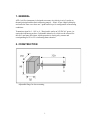
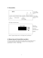
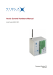
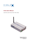
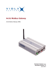
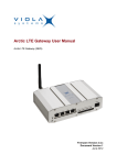
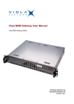
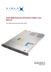
AFD - 1 AIR FLOW TRANSMITTER
WITH DISPLAY
USER MANUAL
1. GENERAL
AFD-1 air flow instrument is designed to measure air-velocity in m/s. It works on
thermal principal and has basic measuring range 0…20m/s. It has 4-digit led display
and under the front cover there are 3 push-button keys for configuration of measuring
conditions.
Transmitter signal is 0…10V or 4…20mA and it works on 24V DC/AC power. As
option the instrument can have 2 adjustable alarm levels, which can be selected for
min (LO) and max (HI) alarm. Alarm operation is closing relay contact and
corresponding led L1 or L2 is indicating alarm situation.
2. CONSTRUCTION
Adjustable flange for duct mounting.
1
3. Connection
LED-lights and push-buttons
Beside 7-segment display there are 4-led-lights and 3 push buttons
4. Measuring and transmitter operation
In measure operation A-led is light and the display indicates the measured value in
m/s and the output signal is following the measured value according ordered
specification 0…10V or 4…20mA range.
2
5. Programming of measuring conditions
1. Coming to programming level
Push arrow keys simultaneously PASS on display, push enter, PASS WORD is
displayed, A and B leds are blinking. Factory setting for pass word is 0. Accept by
ENTER key.
2. Alarm level settings (option)
When password is accepted L1 appears in the display for alarm level L1 settings.
Push ENTER key and select by arrow keys the desired operation
OFF = not in use
LO-A = min alarm
HI –A = for max alarm
When LO-A or HI-A is selected the alarm level value must be set. Set the desired
value by arrow keys and accept the desired value by ENTER key.
Then db (hysteresis) appears in the display. Accept it and set desired value by
arrow keys and accept it with ENTER.
Then dEL (alarm delay) appears in the display. Accept it and set desired delay
value (bigger number = longer delay) by arrow keys and accept it with ENTER.
Programming proceeds to the alarm level L2 settings. Repeat the same procedure
for L2 as for L1.
When the alarm level settings is done OFFS (offset) appears in the display.
Accept it and if you want to move the measuring range, give the new zero-point
value by arrow keys and accept again with ENTER.
(If the transmitter has no alarm programming it just jumps over to the OFFS
position)
FL appears in the display (FL = Filter Function), if the measured flow is
unstable and display is jumping, by bigger FL value the display measuring value
is mean value of longer period measurements. Accept FL, give desired FL-value
with arrow keys and accept it with ENTER key.
3
OP appears in the display (OP = output), if output scaling is just done in
factory or you want to change, accept OP and LO will appear in the display.
Accept LO by ENTER key when the zero value of output signal will appear in the
display (value which corresponds 0V or 4mA). When desired value is selected
accept it by ENTER key.
HI will appear in the display, accept it with ENTER key and the full scale value
of output signal will appear in the display (value which corresponds 10V or
20mA). When desired value is selected accept it with ENTER key.
Now PASS will appear in to the display. Accept PASS and then password will
appear in to the display. If you want to change the password, you can do it here.
When password (old or new) is accepted you come to normal operation level and
programming is ready.
For further information please contact your instrument supplier.
ENVIC OY
Lemminkäisenkatu 46
Turku 20520
Finland
Tel. (02) 4808 2400
Fax. (02) 4808 2404
Email [email protected]
4