1
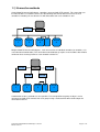
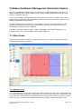
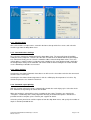
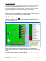
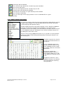
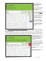
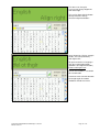
User Manual
Network connection and
Mobics Dashboard (MIS)
software
for
Dryer Controller
M720
Manual version : v1.00
Networking and MIS Manual M720 Dryer controller
Manual version 1
Page 1 of 16
Document history
Preliminary version (v1.00):
Created in February, 2010
Networking and MIS Manual M720 Dryer controller
Manual version 1
Page 2 of 16
Table of contents
Document history..................................................................................................................................... 2
Table of contents ..................................................................................................................................... 3
1) Connecting controllers in a network .................................................................................................... 5
1.1) Connection methods .................................................................................................................... 6
2) Mobics Dashboard (Management Information System)...................................................................... 7
2.1) Main Screen ................................................................................................................................. 7
2.1.1 - Machines list ........................................................................................................................ 7
2.1.2 - Operational data graph........................................................................................................ 8
2.1.3 - Function buttons .................................................................................................................. 8
2.2) Settings menu (per machine)....................................................................................................... 8
2.2.1 - Machine Name..................................................................................................................... 9
2.2.2 - Communications Settings.................................................................................................... 9
2.2.3 - Chart Settings ...................................................................................................................... 9
2.2.4 - Automatic report printing ..................................................................................................... 9
2.2.5 - Web server settings ........................................................................................................... 10
2.3) I/O overview .............................................................................................................................. 10
2.4) Recipe parameters..................................................................................................................... 11
2.5) Print chart................................................................................................................................... 15
2.6) Print report ................................................................................................................................. 15
Networking and MIS Manual M720 Dryer controller
Manual version 1
Page 3 of 16
This page intentionally left blank
Networking and MIS Manual M720 Dryer controller
Manual version 1
Page 4 of 16
1) Connecting controllers in a network
Both the controller and additional I/O boards are fitted with an RJ-45 connector in order to allow
connection to a network using the RS-422 protocol. This also allows connection of the controllers to a
PC. A separate M750 RS-422 to USB adapter is available to facilitate this connection.
In combination with the Mobics Dashboard (MIS) software package (see chapter 12) this connection
option offers a number of possibilities to significantly enhance the way you use the controller:
- Editing recipes and transferring them to/from the controller(s).
- Retrieving batch data from controllers.
- (Automatic) batch/daily report generation and printing (both locally at the dryers or centrally in
the office).
- Remote viewing of dryer status via internet (web application can be viewed on almost any
browser)
Controllers can be connected to a PC individually (using one adapter for each controller), as a network
(a single adapter connected to the PC with all controllers interconnected using UTP cable), or a
combination of these.
For correct functioning each individual controller and I/O extension board must have a unique station
number (see section 6.4.3, item 11). A total of 199 unique numbers are possible.
Each M750 adapter installed on a computer must be assigned a COM port number. With most
Windows versions this happens automatically during installation when the adapter is connected to the
computer
Networking and MIS Manual M720 Dryer controller
Manual version 1
Page 5 of 16
1.1) Connection methods
Single M750 RS-422 to USB adapter, controllers connected with UTP network. This connection can
be realised with less hardware, but has the disadvantage that overall data transfer rate of each
controller is limited by the fact that the PC will collect data from each controller in turn.
M750
M720
1
PC
I/O
M720
3
M720
2
M720
4
Multiple M750 RS-422 to USB adapters, each connected to an individual controller (or controller + I/O
extension board combination). This connection method obviously requires more hardware but will offer
continuous data exchange between each controller and the PC.
M750
PC
M750
M720
1
M720
2
M750
M750
M720
3
I/O
M720
4
Combinations of these methods are also possible. For example different groups of dryers can be
interconnected with UTP network, with each group having a dedicated RS-422 to USB adapter for
connection to the PC.
Networking and MIS Manual M720 Dryer controller
Manual version 1
Page 6 of 16
2) Mobics Dashboard (Management Information System)
There are two additional software packages available for use with the M720 dryer controller. The
Mobics Dashboard (MIS) software allows recipes, settings and operational data to be transferred
between a controller and a PC.
A free version of Mobics Dashboard (Management Information System) is available. This version is
limited to basic functionality and is intended for laundries and service personnel as a tool to assist in
optimal configuration of each controller.
For full functionality a licensed version is also available. The licensed version allows up to 100
controllers to be monitored, reports to be (automatically) generated, and includes web server
functionality for remote real-time monitoring.
The Mobics Translator software enables creation and editing of user-interface languages. It is
available free of charge from the Mobics website (www.mobics.nl).
2.1) Main Screen
A full user manual for this software is available separately. Here we give an overview of the main
functionality provided by the software.
2.1.1 - Machines list (1)
This section of the main screen gives an overview of the machines which have been connected to the
PC and entered into the programme configuration. For each machine it shows the assigned name, and
icons indicate the status of the machine (disconnected, heating, cooling, ready etc). Select any of the
machines in the list and the relevant data from that machine will be shown in the graph area (2).
Networking and MIS Manual M720 Dryer controller
Manual version 1
Page 7 of 16
Selecting a machine with the right mouse button gives access to the settings menu (4 below) where
the parameters of the machine can be modified.
A list of all configured com ports is given below the overview list of machines, and “lights” indicate the
presence of network activity for each port.
2.1.2 - Operational data graph (2)
The graph shown in this part of the main screen is a representation of the activity of the machine
which has been selected in the machines list. It shows the trends for the current cycle of temperature,
humidity etc in addition to heater activity (red blocks along the bottom edge), and the phases through
which the cycle has progressed. In the case shown these are drying, drying on humidity sensor
(optional module for the M720), cooling down, ready, anti-crease (drum rotates to prevent load
becoming creased) and door open (load removed).
Below the graph a list of current alarms is given, alongside an alarm history.
2.1.3 - Function buttons, Selected Machine (3)
These buttons give access to functions for whichever machine is selected in the machines list. Seen
from left to right the buttons give access to the following functions:
I/O overview (2.3 below).
Recipe parameters (2.4 below) with current active recipe shown.
Print chart (2.5 below).
Print report (2.6 below).
Copy graph to clipboard.
2.1.4 - Function buttons, General (4)
These buttons give access to general functions for the Mobics Dashboard programme. Seen from left
to right the functions are as follows:
Add new machine. This opens the machine setup screens (see 2.2).
Info. This opens a window showing licensing information for the software. No licence is
required for the free version which is limited to a single machine.
2.2) Settings menu (per machine)
The settings menu is accessed by right clicking on a controller in the machines list. Two consecutive
screens provide options for individually defining each machine (first screen), and options for printing
data or creating an online (real-time) page for the machine which can be viewed in a web browser.
The programme allows charts and reports to be automatically generated for each machine cycle and
sent to any printer attached to the computer by USB or UTP network.
Networking and MIS Manual M720 Dryer controller
Manual version 1
Page 8 of 16
2.2.1 - Machine Name
Give each machine a unique name, entered in the box at the top of the first screen, and select the
machine type from the drop-down menu.
2.2.2 - Communications Settings
First select the appropriate COM port from the drop-down menu. The menu will show all available
COM ports on the computer, select the one that was created when the M750 USB to RS-422 adapter
was connected. Finally you can select the controller address from the drop-down menu. This is the
unique address (station number) assigned to each controller or I/O extension board and is defined in
the configuration settings of the controller. For further details of how to configure the station number
see the M720 Dryer controller user manual.
2.2.3 - Chart Settings
Selecting the check-box “Automatic chart data reset will reset” the chart data each time the connected
machine starts a new cycle.
Selecting the check-box “Show temperature in Celsius” will display all temperatures in Celsius. By
default temperatures are shown in Fahrenheit.
2.2.4 - Automatic report printing
With this function activated a report is automatically printed after each drying cycle. Select the checkbox “Automatic chart printing” to activate the function.
When the function is activated first select a template for the report. Templates are stored in the
“Templates” subdirectory of the main programme directory and a default template is included. It is
possible to make a template, please contact your supplier for details.
Select the printer you wish to send the reports to from the drop-down menu, and specify the number of
copies in the box provided for this.
Networking and MIS Manual M720 Dryer controller
Manual version 1
Page 9 of 16
2.2.5 - Web server settings
Selecting “Enable web server” in the check-box will turn on the web server built into the programme.
This generates a web page which shows the status of the dryer in real-time. The page can be
accessed from any device which supports web browsing.
To view the web page on the PC to which the controllers are connected (and which is running the
Mobics Dashboard software) type the following into the address bar of your browser:
http://127.0.0.1:8888/Mobics
The above link is the web address of the “local machine” PC. To view the page from other computers
or devices you will need to use the web address for accessing the PC from a remote location. Please
contact your system administrator for details of your network configuration.
2.3) I/O overview
This screen is opened by clicking the
icon in the main screen (see 2.1). It provides status
information for each of the inputs and outputs of the selected controller in addition to power supply
status and any possible error states.
The diagram on the left shows the controller board and connections. Status information is shown in the
diagram and flashing “lights” next to the inputs and outputs indicates activity. If optional extras
(humidity sensor or infrared sensor) are installed and configured on a dryer the status of these will also
be shown.
Select any item from the list of outputs, inputs, and ancillary devices on the right hand side of the
screen to display further information in the text field below the list.
Networking and MIS Manual M720 Dryer controller
Manual version 1
Page 10 of 16
2.4) Recipe parameters
This screen is opened by clicking the
icon in the main screen (see 2.1). It provides options for
managing recipes. With it you can download one or more recipes from a machine on which it has been
created, edit the names, and either upload the recipe(s) to other machines or save them as a backup
on the computer.
Recipes cannot presently be created with this programme, they must be created on a controller. What
this programme does is make it a much simpler task to share recipes with other machines, manage
and back-up commonly used recipes.
When the recipe parameters screen opens it will look similar to the screen above.
At the top is a row of buttons providing various functions (see 2.4.1).
On the left there is a list of all the recipes in the controller. Select any of the recipes by left-clicking the
name in the list.
The rest of the screen is for editing recipe names. On the far right there is a list of available character
sets, ticking the box next to each character set name adds these characters to the overview in the
centre of the screen. Above the character overview are two boxes showing stored (on controller) name
above and edited name below. The green box above this gives a representation of how the name will
look on the screen of the controller. See 2.5.1 for more details on how to edit recipe names.
2.4.1 - Function buttons
These buttons give access to functions for exchanging data with the selected machine. The machine
name is shown in the top left on the title bar for the window. Seen from left to right the buttons give
access to the following functions:
Send recipe names
This resends modified recipe names to the selected controller.
Networking and MIS Manual M720 Dryer controller
Manual version 1
Page 11 of 16
Send recipe data to controller
This sends all recipe data for the selected recipe to the controller.
Save current recipe to file
This saves all recipe data for the selected recipe to a file.
Send all recipes from directory to controller
This loads all saved recipes in a given directory to the controller.
Save all recipes to directory
This saves all recipes in the recipe parameter screen as individual files in a given
directory.
2.4.2 – Editing - Change recipe names
The characters which can be input using your keyboard are defined by the general
settings of your computer. This will vary depending on your location, operating
system language and keyboard settings.
To make inputting characters from other languages easier a long list of additional
character sets have been included in the programme. If you wish to make
translations in Greek for example, you can tick the box next to the Greek character
set. The additional characters will appear in the full list of available characters in
the editing area of the main screen.
You can select as many additional character sets as you wish. It is more practical
however to avoid the list becoming too long by only selecting the character sets
you will really use.
To edit the text place the cursor in
the lower of the two text boxes at
the top left.
Use the keyboard to input text.
Special characters which are not
on the keyboard can be inserted
by using the mouse to select them
from the list.
Pasting text copied to the
clipboard from other sources is
also supported. Both “ctrl-V” and
“right click/Paste” methods can be
used.
To add more characters select
additional character sets from the
list on the right of the arrows by
ticking the boxes.
Networking and MIS Manual M720 Dryer controller
Manual version 1
Page 12 of 16
Some characters may
appear out of alignment
when displayed on the
controller screen.
This can be corrected using
the alignment adjustment
arrows to the right of the
characters list.
- In the text edit box (top left)
place the cursor before the
character to be adjusted.
- Click the left/right/up /down
arrow and select the
appropriate number of
pixels for the adjustment.
- Space and adjustment
characters are shown in
yellow in the text edit box.
- The display simulation
shows how the change will
look on the controller
screen.
NOTE: Adjustments apply for all characters after the adjustment. If you wish to adjust a single character you
need to enter an adjustment before (e.g. +1) and after (e.g. -1) this character so that the remaining text will have
the standard alignment.
Because the resolution of the controller screen is limited (h192 x v32 pixels) there are also limitations on the
number of characters which can be used in a translation. Because different characters use a different number of
pixels it is important to check both characters used and pixels used during the formulation of the translation.
If too many characters are used
while inputting the translation the
text box will show all the
characters, however they will no
longer appear in the display
simulation.
When the character or pixel limit
for a translation is reached the
boxes showing used/remaining
characters or pixels will turn red
to indicate that a shorter
formulation is needed.
Space characters use 1 character
and 3 pixels.
Adjustment “characters” use one
available character space.
Networking and MIS Manual M720 Dryer controller
Manual version 1
Page 13 of 16
For some texts it may be
necessary to change alignment
from left to right.
This can be done with the button
directly below the orange
character alignment buttons.
Some languages, like for example
Arabic, are read (and written)
from right to left.
To input text for these languages
click the text direction button
(below the text alignment button)
before entering the text.
All text entered will be saved with
this text direction.
In order to enter text with direction
left to right again the button
should be clicked once more.
Networking and MIS Manual M720 Dryer controller
Manual version 1
Page 14 of 16
2.5) Print chart
This screen is opened by clicking the
icon in the main screen (see 2.1). Allows printing of current
graph to any printer installed on the PC, with basic options to adjust the chart for readability.
2.6) Print report
icon in the main screen (see 2.1) generates and prints a full report of the last cycle of
Clicking the
the selected machine. Reports are based around templates which can be custom-created, so allowing
the customer to make reports in the format that suits them best, and with company logo’s etc. Reports
can also be generated automatically after each cycle. This can be configured in the settings menu
(see 2.2).
An example of a report is shown on the next page.
Networking and MIS Manual M720 Dryer controller
Manual version 1
Page 15 of 16
Example of report generated automatically by Mobics Dashboard software.
Networking and MIS Manual M720 Dryer controller
Manual version 1
Page 16 of 16