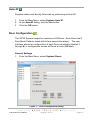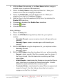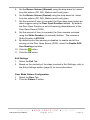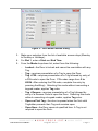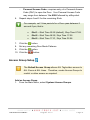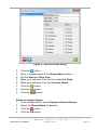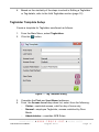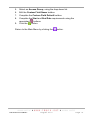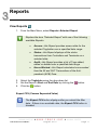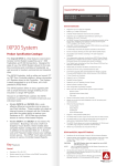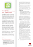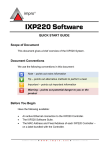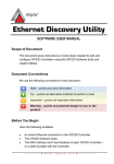
1
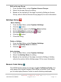
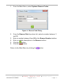
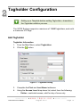
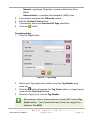
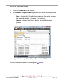
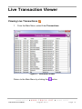
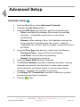
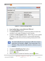
IXP20 (Web Interface) USER MANUAL Scope of Document This document gives a brief overview of operation of the IXP20 Controller’s Web user interface. Document Conventions We use the following conventions in this document: Note – points out extra information Tip – points out alternative methods to perform a task Important – points out important information Warning – points out potential danger to you or the product Before You Begin Have the following available: An active Ethernet connection to the IXP20 Controller (using a standard Ethernet cable). The latest version of Java Runtime Environment installed. 1 System Settings Installing Java Runtime Environment (JRE) 1. 2. 3. 4. 5. 6. 7. Using Windows® Internet Explorer go to www.java.com. On the Home Page, click on the Free Java Download button. Click the Install button. At the Java Setup – Welcome dialog, click the Accept > button. At the Java Setup – Complete dialog, click the Finish button. Close Internet Explorer. Restart your PC. Starting the IXP20 Web Interface Over a LAN Do NOT open more than 1 instance of the Web Interface per Controller. When using the Web Interface with the Touch Screen Controller, ensure the screen is locked. If the Web Server resides on a Port other than Port 80, the URL becomes: http://ixp20:XX/. The XX highlighted in the URL refers to the new Port number. If your Controller connects direct to the PC, refer to page 24 for information on accessing the Web Interface. 1. 2. 3. 4. In your Internet Browser go to http://ixp20/. At the Security Warning, click the Run button. Click the OK button. Select a location in which to save the Backup. Backup takes place automatically at startup, retaining the 5 most recent backups. ISC306-0-0-GB-01 August 2010 Page 2 5. Click the Open button. Over a WAN When the Web Interface loads, it tries to connect to the Controller using the hostname and the Controller’s configured port. This hostname is only valid on the LAN. If the Web Interface tries to connect to the Controller from another network or across the internet, provide the router with a public static IP Address or a dynamic hostname and configure port forwarding. 1. 2. 3. 4. 5. 6. In your internet browser go to http://ixp20/. At the Controller Connection Error dialog, click the Yes button. Enter the Hostname or IP Address for the Controller. Click the OK button. Enter the Host Port for the Controller. Click the OK button. The next time you load the Web Interface on the same computer, logged in as the same user, the values used for the alternative Hostname and alternative Host Port load as defaults into the Hostname and Host Port textboxes. Date or Time Setup 1. 2. 3. 4. 5. 6. From the Main Menu, select System>Date/Time. Synchronise the IXP20 Controller’s Date and Time to your PC by clicking the button. Set the Start and End Date for Daylight Savings using the buttons. Set the time that Daylight Savings takes effect using the Switch Time textbox. Set the duration of the Daylight Savings time shift using the Shift Duration textbox. Click the button. ISC306-0-0-GB-01 August 2010 Page 3 Auto-ID Populate tables and identify Terminals by performing an Auto-ID: 1. 2. 3. From the Main Menu, select System>Auto ID. At the Auto-ID dialog, click the Yes button. Click the OK button. Door Configuration The IXP20 System supports a maximum of 8 Doors. Each Door has 3 Door Mode Patterns (each with 4 time period allocations). The user interface allows for configuration of each Door individually (labeled 1 through 8) or configuration across all Doors at once (All label). General Settings 1. From the Main Menu, select System>Doors. Figure 1 – Door Configuration Dialog ISC306-0-0-GB-01 August 2010 Page 4 2. 3. 4. 5. 6. 7. 8. With the Door Tab selected, in the Door Name textbox, assign a suitable name (maximum 16 characters). Select the Entry Reader using the drop-down list. Make your selection from the list of displayed Readers. Select the Exit Reader using the drop-down list. Make your selection from the list of displayed Readers. Add the Door to the Anti-passback (APB) Zone, by selecting the Enable APB checkbox. If necessary, de-select the Enable Door checkbox. Click the button. Click the OK button. Entry Settings 1. Select the Entry Tab. 2. Select the RTE Mode using the drop-down list, your options include: Normally Closed—sensor remains closed until opened by an operator. Normally Open—sensor remains open until closed by an operator. 3. Edit the DOS Mode using the drop-down list, your options include: Normally Closed Normally Open 4. Edit the DOS Usage using the drop-down list, your options include: Normal—alarm sounds if the Door remains open too long or if the Doors forced. Use this feature for monitoring real Door open states. Inhibit Reader—deactivates the Reader as long as the Door is open; also there is no alarm for Doors forced open. Used to disable the reader while the Door remains open. Terminate Strike—deactivates the relay if Door is opened and closed or forced. Use this feature where the lock must reengage once the Door is closed. ISC306-0-0-GB-01 August 2010 Page 5 5. Set the Buzzer Volume (Allowed) using the drop-down list, select from the options (Off, Soft, Medium and Loud) given. 6. Set the Buzzer Volume (Denied) using the drop-down list, select from the options (Off, Soft, Medium and Loud) given. 7. Set the amount of time (in seconds) the Door stays open before an alarm triggers using the Door Open Duration textbox. By default, the Door Open Duration is set to 0 meaning disenablement of the Door Open Sensor (DOS). 8. Set the amount of time (in seconds) the Door remains unlocked using the Strike Duration (in seconds) textbox. The maximum Strike Duration is 999 999. 9. By default end-of-line sensing is disabled, to enable end-of-line sensing on the Door Open Sensor (DOS), select the Enable DOS Line Sensing checkbox. 10. Click the button. 11. Click the OK button. Exit Settings 1. Select the Exit Tab. 2. Based on the similarity of the steps involved in Exit Settings, refer to the Entry Settings section (page 5) for more information. Door Mode Pattern Configuration 1. Select the Door Tab. 2. Click the Pattern 1 button. ISC306-0-0-GB-01 August 2010 Page 6 Figure 2 – Door Mode Patterns Dialog 3. 4. 5. Make your selection from the list of available access days (Monday to Sunday or Holidays). For Slot 1, enter a Start and End Time. From the Mode drop-down list, select from the following: Locked—the Door is locked and cannot be overridden with any Tag. Tag—requires presentation of a Tag to open the Door. Tag + PIN—requires presentation of a Tag followed by entry of a PIN-code to open the Door. PIN-codes range from 2 to 65534. After entering the PIN-code, complete the entry by pressing the # key). Selecting this mode without connecting a keypad reader, applies Tag rules. Tag + Reason—requires presentation of a Tag followed by entry of a Reason Code to open the Door. Selecting this mode without connecting a keypad reader, applies Tag rules. Open on First Tag—the door is opened when the first valid Tagholder presents their Tag and remains open. Open Now—the Door opens at specified time. A Tag is not required to open the Door. ISC306-0-0-GB-01 August 2010 Page 7 6. Personal Access Code—requires entry of a Personal Access Code (PAC) to open the Door. Your Personal Access Code may range from between 1 to 9999 followed by a # symbol. Repeat steps 4 and 5 for the remaining Slots. For example, set 3 time periods for a Door open between 8 am and 5 pm, that is: 7. 8. 9. 10. Slot 1—Start Time 00:00 (default), Stop Time 07:59. Slot 2—Start Time 08:00, Stop Time 17:00. Slot 3—Start Time 17:01, Stop Time 23:59. Click the button. Set any remaining Door Mode Patterns. Click the button. Click the button. Access Group Setup The Default Access Group allows ALL Tagholders access to ALL Doors at ALL times. Therefore, create Access Groups to restrict or allow access as required. Add an Access Group 1. From the Main Menu, select System>Access Groups. ISC306-0-0-GB-01 August 2010 Page 8 Figure 3 – Access Groups Dialog 2. 3. 4. 5. 6. 7. 8. 9. Click the button. Enter a suitable name in the Group Name textbox. Set the Start and Stop Time. Make your selection from the list of available Days. Make your selection from the displayed Doors. Click the button. Click the OK button. Click the button. Delete an Access Group 1. From the Main Menu, select System>Access Groups. 2. Select the Group Name for deletion. 3. Click the button. 4. Click the OK button. ISC306-0-0-GB-01 August 2010 Page 9 Edit an Access Group 1. From the Main Menu, select System>Access Groups. 2. Select the Access Group for editing. 3. Based on the similarity of the steps involved in Editing an Access Group, refer to Add an Access Group (page 8) for more information. Holidays Setup Add a Holiday 1. From the Main Menu, select System>Holidays. 2. Click the button. 3. Enter a suitable name in the Holiday Name textbox. 4. Set the Start Date by clicking the button. 5. Set the End Date by clicking the button. 6. Click the button. 7. Close the dialog. Delete a Holiday 1. From the Main Menu, select System>Holidays. 2. Select the Holiday Name for deletion. 3. Click the button. Edit a Holiday 1. From the Main Menu, select System>Holidays. 2. Select the Holiday Name for editing. 3. Based on the similarity of the steps involved in Editing a Holiday, refer to the section Add a Holiday (page 10) for more information. Reason Code Setup The IXP20 System allows for storage of up to 10 Reason Codes. You may assign any number between 0 and 99 as a Reason Code, letting you to keep legacy Reason Codes to avoid retraining employees. ISC306-0-0-GB-01 August 2010 Page 10 1. From the Main Menu, select System>Reason Codes. Figure 4 – Reason Code Dialog 2. 3. 4. 5. 6. From the Reason Slot drop-down list, select a number between 1 and 10. Enter a number between 0 and 99 in the Reason Number textbox. Enter a suitable description in the Reason textbox. Click the button. Click the button. Return to the Main Menu by clicking the ISC306-0-0-GB-01 August 2010 button. Page 11 2 Tagholder Configuration Setting up a Template before adding Tagholders, streamlines the Tagholder addition process. The IXP20 System supports a maximum of 1 000 Tagholders, each with a maximum of 3 Tags. Add Tagholder Tagholder Information 1. From the Main Menu, select Tagholders. 2. Click the button. Figure 5 – Tagholder Dialog 3. 4. Complete the First and Last Name textboxes. Using the Access Level drop-down list, select from the following: Visitor—restricted access, valid for day of issue only. ISC306-0-0-GB-01 August 2010 Page 12 5. 6. 7. 8. Normal—employee Tagholder, access restricted by Door Mode. Administrator—overrides Anti-passback (APB) rules. If necessary, complete the PIN-code textbox. Edit the Custom Field textbox. If necessary, select the Suspend All Tags checkbox. Click the button. Tag Information 1. Click the Tag1 button. Figure 6 – Tag Dialog 2. 3. 4. Select your Tag registration reader using the Tag Reader dropdown list. Click the button alongside the Tag Code textbox, or type the tag code into the Tag Code textbox. Present a Tag to your chosen Tag Reader. Alternatively, enter a Personal Access Code (PAC) in the Tag Code textbox. Your Personal Access Code may range from between 1 to 9999. ISC306-0-0-GB-01 August 2010 Page 13 5. 6. 7. 8. From the Access Group drop-down list, make your selection. Complete the Start and End Date requirements using the associated buttons. If necessary, select the Suspend All Tags checkbox. Click the button. Add a Batch of Tags 1. 2. 3. 4. 5. 6. 7. From the Main Menu, select Tagholders. Click the button. Select your Tag registration reader using the Select Reader dropdown list. At the Batch Enrollment screen, click the button. Present each Tag in succession to the IXP20 Controller. After enrolling the batch of Tags, click the button. Click the button. Delete a Tagholder or Tag 1. 2. 3. 4. From the Main Menu, select Tagholders. Select the Tagholder you wish to delete. Click the button. At the confirmation message, click Yes. Alternatively, if you would like to delete just the Tag (keeping the Tagholder enrolled in the System), click the Tag1, Tag2 or Tag3 button representing the Tag for deletion. Edit Tagholders or Tags 1. 2. 3. From the Main Menu, select Tagholders. Select the Tagholder for editing. Click the button. ISC306-0-0-GB-01 August 2010 Page 14 4. Based on the similarity of the steps involved in Editing a Tagholder or Tag details, refer to the Add Tagholder section (page 12). Tagholder Template Setup Create a template for Tagholder enrollment as follows: 1. 2. From the Main Menu, select Tagholders. Click the button. Figure 7 – Tag Template Dialog 3. 4. Complete the First and Last Name textboxes. From the Access Level drop-down list, select from the following: Visitor—restricted access, valid for day of issue only. Normal—employee Tagholder, access restricted by Door Mode. Administrator—overrides APB Rules. ISC306-0-0-GB-01 August 2010 Page 15 5. 6. 7. 8. 9. Select an Access Group, using the drop-down list. Edit the Custom Field Name textbox. Complete the Custom Field Default textbox. Complete the Start and End Date requirements using the associated buttons. Click the button. Return to the Main Menu by clicking the ISC306-0-0-GB-01 August 2010 button. Page 16 3 Reports View Reports 1. From the Main Menu, select Reports>Selected Report. Replace the term ―Selected Report‖ with one of the following available Reports: 2. 3. 4. Access—this Report provides access data for the selected Tagholder over a specified date range. Status—this Report displays all the status transactions from Controllers and Terminals on a selected date. Audit—this Report provides a list of Tags added, edited or deleted over a specified date range. Hours Worked—this Report calculates hours worked from the IN and OUT Transactions of the Antipassback (APB) Zone. Select the Tagholder using the drop-down list. Set the Report’s Start and End Date by clicking the Click the button. button. Export CSV (Comma Separated Value) The Export CSV button displays after you submit the filter data. If there is no available data, the Export CSV button is disabled. ISC306-0-0-GB-01 August 2010 Page 17 Export a Report as follows: 1. Click on the Export CSV button. 2. In the Select Output File dialog select one of the following button options: Save—clicking the Save button, gives you the option to save the exported data to a location of your choice. Cancel—clicking the Cancel button, cancels the export process. Figure 8 – Message Board Report Exported in CSV Format Return to the Main Menu by clicking the ISC306-0-0-GB-01 August 2010 button. Page 18 Live Transaction Viewer Viewing Live Transactions 1. From the Main Menu, select Live Transactions. Figure 9 – Transaction Viewer Return to the Main Menu by clicking the ISC306-0-0-GB-01 August 2010 button. Page 19 4 Advanced Setup Controller Setup 1. 2. 3. 4. 5. 6. 7. 8. From the Main Menu, select Advanced>Controller. Complete the Site Name textbox. Using the APB Type drop-down list, select from the following: Strict—enforced Anti-passback Zone rules for in and out directions. A Tagholder cannot enter or exit a Zone consecutively. Relaxed—after entering a Zone, the Tagholder must exit the Zone using their Tag before they can re-enter. However, Tagholders can use their Tags for multiple, consecutive exits in this Mode. Using the Door Type drop-down list, select from the following: Emergency Open—opens all Doors immediately. Lock Down—locks all Doors immediately. Normal—Doors operate as set up. Select the Reset APB checkbox if required. The Off-line Validation checkbox is selected by default, allowing Terminals connected to the Controller to make certain access control decisions even when unable to communicate with the Controller. De-select the checkbox if necessary. The Display TFT Transactions checkbox is selected by default, de-select the checkbox if necessary. Click the button. ISC306-0-0-GB-01 August 2010 Page 20 Ethernet Figure 10 – Ethernet Settings Dialog 1. 2. 3. 4. From the Main Menu, select Advanced>Ethernet. Edit the Device Name textbox. The Enable DHCP checkbox is selected by default, de-select the checkbox to set a static IP Address for the Controller. Complete the Safe IP (Host) textbox. Safe IP lets you set a specific IP address for the IXP20 Controller to communicate exclusively with. This provides extra security by limiting access points to the System. The default Web Browser Port Number is 80 and the default Application Port Number is 10005. Only change these Port Numbers, if they clash with other devices or services on your network. 5. 6. 7. 8. Complete the Web Browser Port textbox. Complete the Application Port textbox. Click the button. When prompted to re-start the Controller, click the ISC306-0-0-GB-01 August 2010 button. Page 21 Restore Restore the Controllers configuration settings as follows: 1. 2. 3. 4. 5. 6. From the Main Menu, select Advanced>Restore. In the Open dialog, browse to your chosen Backup location. Select the file for restoration. Click the Open button. At the Message dialog, click the OK button. At the Restart Required dialog, click the OK button. Thus restarting the Web Interface, restoring your configuration settings. UDP Output The UDP Output feature sends events generated in the IXP20 System to a third-party application. Configure this feature as follows: 1. 2. 3. 4. From the Main Menu, select Advanced>UDP Output. Select the Enable UDP checkbox. Complete the Receiving IP textbox. Complete the Receiving Port textbox. The default Receiving Port Number is 10010. Only change this Port Number if it clashes with other devices or services on your network. 5. 6. Set the time (in seconds) between notifications using the Keep Alive Time textbox. The default Keep Alive Time is 60 seconds. Click the button. Replace Unit 1. 2. From the Main Menu, select Advanced>Replace Unit. Using the Replace drop-down list, make your selection. ISC306-0-0-GB-01 August 2010 Page 22 3. 4. 5. Complete the With textbox referring to the Fixed Address of the replacement unit. Click the button. At the confirmation message, click Yes. Security Set or change the administrator password as follows: 1. 2. 3. 4. 5. From the Main Menu, select Advanced>Security. Complete the New Code textbox. Complete the Confirm Code textbox. Click the button. Click the OK button. Return to the Main Menu by clicking the button. Other Advanced Features Manual Backup Back up your Controller Configuration Settings as follows: 1. 2. From the Main Menu, select About. At the About Dialog, click the Backup Now button. Backup saves to the same location selected in the section Starting the IXP20 Web Interface on page 2. ISC306-0-0-GB-01 August 2010 Page 23 Troubleshooting Restoring Factory Defaults Restoring factory defaults will reset the IXP20 Controller’s device name to IXP20. 1. Set the Door Lock Select DIP-switch Switch 1 to the ON position. Refer to your IXP20 Controller’s Hardware Installation Manual for location of the DIP-switch. 2. 3. Reset the Controller by removing and then reapplying the power source. With the Controller running, set the Door Lock Select DIP-switch Switch 1 back to the OFF position. Connecting the IXP20 Controller direct to a PC When using more than one IXP20 Controller, ensure each Controller has a unique Device Name (see page 21). Setting a static IP Address for your Controller may result in difficulties when connecting direct to a PC. If the Enable DHCP checkbox has previously been de-selected in the Web Interface, ensure that you reselect the Enable DHCP checkbox before continuing (see page 21 for more information). ISC306-0-0-GB-01 August 2010 Page 24 When connecting the Controller direct to a PC or Switch without a DHCP server, it takes about 30 seconds before the Controller gets assigned the default IP Address of 192.168.100.1. On the PC 1. Select Start>Control Panel. 2. Click the Network and Sharing Centre icon. 3. Select Local Area Connection. 4. Click the Properties button. 5. Select the Internet Protocol Version 4 (TCP/IPv4) option. 6. Click the Properties button. 7. Set the IP Address to 192.168.100.X (X being any available number between 2 and 254. Ensure that your chosen number is unique between all IXP20 Controllers and the PC.). 8. Set the Subnet Mask to 255.255.255.0 9. Click the OK button. ISC306-0-0-GB-01 August 2010 Page 25 Extra Information Further information is available at the following resources: IXP20 (Touch Screen User Interface) User Manual (ISC305-0-0-GB-XX). ImproX IXP20 System Product Specification Catalogue (ISC353-0-0-GB-XX). ImproX IXP20 Controller Installation Manual (ISC303-0-0-GB-XX and ISC304-0-0-GB-XX). ImproX IXP20 Firmware Upgrade Utility User Manual (ISC307-0-0-GB-XX). Download the ImproX IXP20 Firmware Upgrade Utility from the following URL: www.impro.net. The referenced documents are available for download at www.impro.net. Alternatively, contact your Impro dealer for a copy. User Notes ISC306-0-0-GB-01 August 2010 Page 26 User Notes ISC306-0-0-GB-01 August 2010 Page 27 User Notes This manual is applicable to the IXP20 Web Interface V 2.04. (The last two digits of the Impro stock code indicate the issue status of the product). ISC306-0-0-GB-01 ISC306-0-0-GB-01 Issue 02 Aug 2010 August 2010 IXP20S\Software\English Manuals\LATEST ISSUE\20Web-swm-en-02.docx Page 28