1
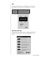
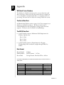
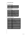
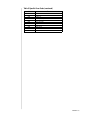
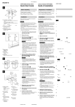
WD Quick Tester
User Manual
Information furnished by Western Digital is believed to be accurate and reliable. However, no responsibility
is assumed by Western Digital for its use; nor for any infringement of patents or other rights of third parties
which may result from its use. No license is granted by implication or otherwise under any patent or patent
rights of Western Digital. Western Digital reserves the right to change specifications at any time without
notice.
© 2004 Western Digital Technologies, Inc. All rights reserved.
Western Digital is a registered trademark, and WD and the WD logo are trademarks of Western Digital
Technologies, Inc. Other marks may be mentioned herein that belong to other companies.
2779-001003-A01 11/04
Contents
Important - Read First . . . . . . . . . . . . . . . . . . . . . . . . . . . . . . . . . . . . . . . . 1
Hard Drive Handling Procedures . . . . . . . . . . . . . . . . . . . . . . . . . . . . . . . . 1
2
Setup
Introduction . . . . . . . . . . . . . . . . . . . . . . . . . . . . . . . . . . . . . . . . . . . . . . . . 2
WD Quick Tester Kit Contents . . . . . . . . . . . . . . . . . . . . . . . . . . . . . . . . . 2
Specifications . . . . . . . . . . . . . . . . . . . . . . . . . . . . . . . . . . . . . . . . . . . . . 2
Features at-a-Glance . . . . . . . . . . . . . . . . . . . . . . . . . . . . . . . . . . . . . . . . 2
Quick Start Operations. . . . . . . . . . . . . . . . . . . . . . . . . . . . . . . . . . . . . . . . 3
Preparing a Drive for Testing . . . . . . . . . . . . . . . . . . . . . . . . . . . . . . . . . . . 3
4
Testing the Hard Drive
Jumper Settings. . . . . . . . . . . . . . . . . . . . . . . . . . . . . . . . . . . . . . . . . . . . . . 4
LEDs . . . . . . . . . . . . . . . . . . . . . . . . . . . . . . . . . . . . . . . . . . . . . . . . . . . . . 5
Quick Start Guide Label . . . . . . . . . . . . . . . . . . . . . . . . . . . . . . . . . . . . . . . 5
Main Menu . . . . . . . . . . . . . . . . . . . . . . . . . . . . . . . . . . . . . . . . . . . . . . . . 6
Initialization Process . . . . . . . . . . . . . . . . . . . . . . . . . . . . . . . . . . . . . . . . 6
Full Drive Test . . . . . . . . . . . . . . . . . . . . . . . . . . . . . . . . . . . . . . . . . . . . 7
Quick Drive Test . . . . . . . . . . . . . . . . . . . . . . . . . . . . . . . . . . . . . . . . . . 7
Drive Failure Notification . . . . . . . . . . . . . . . . . . . . . . . . . . . . . . . . . . . . 8
Drive Pass Notification . . . . . . . . . . . . . . . . . . . . . . . . . . . . . . . . . . . . . . 8
Full Drive Erase. . . . . . . . . . . . . . . . . . . . . . . . . . . . . . . . . . . . . . . . . . . . 9
Quick Drive Erase . . . . . . . . . . . . . . . . . . . . . . . . . . . . . . . . . . . . . . . . . . 9
Utility Menu. . . . . . . . . . . . . . . . . . . . . . . . . . . . . . . . . . . . . . . . . . . . . . . 10
Test Data Ops. . . . . . . . . . . . . . . . . . . . . . . . . . . . . . . . . . . . . . . . . . . . 10
Time . . . . . . . . . . . . . . . . . . . . . . . . . . . . . . . . . . . . . . . . . . . . . . . . . . . 10
Comm Settings . . . . . . . . . . . . . . . . . . . . . . . . . . . . . . . . . . . . . . . . . . . 11
12
Appendix
WD Quick Tester Database . . . . . . . . . . . . . . . . . . . . . . . . . . . . . . . . . . . 12
The Serial Data Port . . . . . . . . . . . . . . . . . . . . . . . . . . . . . . . . . . . . . . . . . 12
The RS232 Data Port . . . . . . . . . . . . . . . . . . . . . . . . . . . . . . . . . . . . . . . . 12
Data Format . . . . . . . . . . . . . . . . . . . . . . . . . . . . . . . . . . . . . . . . . . . . . . . 12
Collecting Data to a Desktop or Laptop System . . . . . . . . . . . . . . . . . . . . 13
Firmware Updates. . . . . . . . . . . . . . . . . . . . . . . . . . . . . . . . . . . . . . . . . . . 13
Battery Replacement . . . . . . . . . . . . . . . . . . . . . . . . . . . . . . . . . . . . . . . . . 14
Error Code Description . . . . . . . . . . . . . . . . . . . . . . . . . . . . . . . . . . . . . . 15
Table 1: Main Test Codes . . . . . . . . . . . . . . . . . . . . . . . . . . . . . . . . . . . 15
Table 2: Subtest Codes . . . . . . . . . . . . . . . . . . . . . . . . . . . . . . . . . . . . . 15
Table 3: Specific Error Codes . . . . . . . . . . . . . . . . . . . . . . . . . . . . . . . . 15
Table 3: Specific Error Codes (continued). . . . . . . . . . . . . . . . . . . . . . . 16
WD Service and Support . . . . . . . . . . . . . . . . . . . . . . . . . . . . . . . . . . . . . 17
CONTENTS - i
Important - Read First
Western Digital does not warrant or represent in any way that the WD
Quick Tester will function with all make/model EIDE hard drives or
identify all faulty drives under test.
The WD Quick Tester may not identify and/or fail drives that
function intermittently. Such drives may be able to function but with
some difficulty and may only occasionally report an error or failure
when tested. The frequency of intermittent failures can change by
varying the test conditions, making an actual failure of the drive
difficult to identify.
Hard Drive Handling Procedures
Hard drives can be damaged by rough handling, shock and vibration,
or electrostatic discharge (ESD). Be aware of the following precautions
when handling hard drives.
!
!
!
!
!
Follow all proper static electricity handling procedures before
attempting to test any hard drive. To avoid ESD, ground yourself
by touching the metal chassis of the computer or wear a
grounding strap before handling the hard drive.
Articles of clothing generate static electricity. Do not allow
clothing to come in direct contact with the hard drive or circuit
board components.
Handle the hard drive by the sides only. Avoid touching the circuit
board components on the bottom of the hard drive.
Do not drop, shake, or knock down the hard drive.
Do not stack hard drives or stand the hard drive on its edge.
-1
1
Setup
Introduction
The Western Digital Quick Tester is a simple-to-use universal EIDE
hard drive tester that requires no prior hard drive testing experience. It
was designed to work on all EIDE drives that support the Logical
Block Addressing (LBA) mode of operation. To operate, attach the
drive to the tester via the included 40-pin EIDE cable, apply power to
both tester and drive, and follow the directions as displayed on the
Liquid Crystal Display (LCD). A computer system is not required,
but may be used to supply power to the WD Quick Tester and hard
drive.
WD Quick Tester Kit Contents
!
!
!
!
WD Quick Tester
4-conductor power supply "Y" cable
40-pin EIDE cable
WD Quick Tester Quick Reference
Specifications
!
Standard voltage level RS232 interface
!
Thermal resetable power line fuse
!
Environmental: from 5o to 45o C, non-condensing
!
Power requirements: 12V @ 300 ma; 12 VDC ±10%; ripple and
noise 250 mV provided by the 4-pin Molex connector
Features at-a-Glance
!
Stand-alone tester, a PC is not required for test operation
!
Designed to test all hard drives that support LBA mode with
enhanced test algorithms for Western Digital drives
!
Easy-to-use with simple Pass/Fail results
!
Two-button operation with prompted user messages on a
16-character by 2-line LCD
!
Drive testing using internal drive S.M.A.R.T.TM features if
supported
!
Two test options: Quick Drive Test and Full Drive Test (full media
scan with repair functionality)
!
Two erase functions: Quick Erase and Full Erase operation
!
Logging of up to 100 test records in battery backed up SRAM
!
Support of an RS232 serial data output of the tester database
SETUP - 2
Quick Start Operations
1. Verify that the drive jumpers are set for either Single or Cable
Select operations.
2. Attach the tester to the drive using the provided 40-pin EIDE
cable.
3. Attach both tester and drive to a power source and apply power.
Follow the user messages as displayed on the LCD screen. If testing a
non Western Digital drive, refer to the manufacturer’s instructions for
jumper settings.
Caution: Though the Quick/Full Drive Test is not data destructive,
data within all bad sectors will be overwritten. Make sure to back up
your data.
Preparing a Drive for Testing
The following steps will help you ensure proper usage of the WD
Quick Tester.
1. Check jumper settings: Jumper settings determine the number of
devices on a cable in a computer system. The WD Quick Tester
supports one hard drive attached at any one time and only certain
jumper settings. Western Digital hard drives must be jumpered as
Cable Select or Single (refer to the Jumper Settings section on page
3). For non Western Digital hard drives, refer to the manufacturer’s
documentation.
2. Check the cable connection: The WD Quick Tester is supplied
with an EIDE cable. Verify that the cable is in good working
condition and that pin 1 on both hard drive and tester are aligned.
Of the 40 pins on an EIDE connector, pin 1 is designated in red.
Most EIDE cables are keyed to fit the connector only one way.
IMPORTANT: The EIDE cable must remain in proper working
condition to ensure accurate test results.
3. Check power: The WD Quick Tester uses a standard 12 V, 4-pin
connector on a PC power supply. Verify that the connector you are
using is in proper working condition. This connector is also keyed
and cannot be reversed but will fit either the hard drive or tester. If
the power connector is not attached, the WD Quick Tester may
display invalid messages.
SETUP - 3
2
Testing the Hard Drive
Jumper Settings
For the hard drive to be detected by the WD Quick Tester, the drive
must be jumpered according to the manufacturer’s instructions. Verify
that the jumper settings on the hard drive are supported by the WD
Quick Tester. Western Digital hard drives must be jumpered as Cable
Select or Single (see diagram below). For non Western Digital hard
drives, refer to the manufacturer’s documentation.
Cable Select
1
(Default Setting)
2
975 31
10 8 6 4 2
3
10-PIN
CONNECTOR
Dual
Dual
Dual
Dual
Dual
975 31
10 8 6 4 2
Single
975 31
(Master)
(Master)
(Master)
(Master)
(Master)
10-PIN
CONNECTOR
KEY:
10 8 6 4 2
4
Dual
(Slave)
975 31
10 8 6 4 2
Jumper pins
10-PIN
CONNECTOR
10-PIN
CONNECTOR
Jumper added
Supported by the WD Quick Tester:
!
!
Cable Select (CSEL/CS): Jumper settings remain the same on all
hard drives in a system (both single- and multi-drives setups). This
protocol requires a special CSEL cable, and the host system must
support CSEL. The WD Quick Tester supports this setting.
Single: Indicates the only drive on the cable. Three distinct
configurations on Western Digital hard drives are a) pins 3 and 5
for older models, b) pins 4 and 6 for current 10-pin drives, and c)
the simplest, for late model drives, all jumpers removed. The WD
Quick Tester supports all three configurations of the Single
setting.
Not supported by the WD Quick Tester:
!
!
Master: Designates the drive as the boot device or first device
detected on the cable and that a Slave device is present. The WD
Quick Tester does not support the Master setting on Western
Digital hard drives because these drives have unique
configurations for Master and Single. However, the Master setting
is supported on other manufacturer hard drives that share the
same configuration for Master and Single.
Slave: Designates the drive for use as additional storage and that
another device (a Master or boot drive) is on the cable. The WD
Quick Tester does not support this setting.
TESTING THE HARD DRIVE - 4
LEDs
The WD Quick Tester features two LED indicators on the front for
user notification. When lit, either or both LEDs denote a particular
status.
LED
Red
Green
Red and Green
Indicates
Failure
Requested task completed successfully
Requires user action
Quick Start Guide Label
The Quick Start Guide label is located on the back of the WD Quick
Tester. The main steps and their functions are highlighted for easy
reference.
TESTING THE HARD DRIVE - 5
Main Menu
Press the Next/No button and continue until the function you wish to
perform is displayed. Execute the choice by pressing the Select/Yes
button.
Initialization Process
The initialization process is the same for all four drive-related
functions. The initialization process for the WD Quick Tester
performs the following:
1.
2.
3.
4.
5.
6.
7.
8.
Checks if a drive is connected.
Checks if the drive is configured properly as a Single drive.
Executes the drive’s internal diagnostics.
Executes the Identify Drive Command to obtain drive
information. The model information is briefly displayed.
Determines the drive’s features and verifies LBA support.
Verifies that the drive does not have "Security" enabled.
Enables the S.M.A.R.T. feature set if supported.
Checks S.M.A.R.T. thresholds if supported.
Message
No Drive Found! Check Connection.
Drive Detected, but NOT READY.
Device Not Ready. Check Connection.
Check Jumper. Power Cycle Drv.
Bad Cable? Check Connection.
## Drive FAIL ##, ## Press Next ##
No LBA Support. Can’t Test Drive.
Security Enabled. Unable to Test.
Condition
Does not detect a device attached to the data cable.
Detects the device, but device never becomes ready.
Requires user action.
Drive not configured as a "Single" Device.
Detected Bad Cable.
Drive fails Drive Diagnostic Command.
Drive does not support LBA mode addressing.
Drive security feature is enabled.
If the drive passes the above operation, the Quick Tester then
performs the selected test function.
TESTING THE HARD DRIVE - 6
Full Drive Test
Caution: Though the Quick/Full Drive Test is not data destructive,
data within all bad sectors will be overwritten. Make sure to back up
your data.
Highly recommended for all test procedures, the Full Drive Test
provides the most extensive testing of the two test functions. Test time
for the Full Drive Test varies depending on the capacity of the drive
under test. New generation drives will test at greater than 1 GB per
minute while old generation drives may test at less than 10 MB per
minute. Test progress is displayed on the second line of the tester
LCD. If errors are detected during this operation, the WD Quick
Tester will correct the bad sector.
If the drive passes the testing, it is spun down, and the drive
information and test data are stored in the tester database. The WD
Quick Tester will report that the test is completed and that the drive
passed, indicated by both a message on the display and an illuminated
green LED. DO NOT return a drive for repair if it passed the test.
If the drive fails at any point in the testing, the WD Quick Tester
attempts to spin down the drive and notifies the user. If the drive
failed for user-induced handling damage, DO NOT return the drive
for warranty repair. If the drive failed for non-customer handling
related issues, the WD Quick Tester will report the failure. In both
failure cases, the red LED illuminates. The drive information and test
data are stored in the tester database.
At any time during the Full Drive Test, you can abort the operation by
pressing either button. When the test stops, you are given the choice
to Abort or Return to the test. Selecting Abort results in no report on
the display.
Quick Drive Test
The Quick Drive Test is identical to the Full Drive Test except that it
does not perform the full media scan unless it detects an error during
testing. The Quick Drive Test may not identify all media-related
errors, but it does test the basic functionality of a drive. If you suspect
media issues, use the Full Drive Test function. If the WD Quick
Tester detects a media-related failure, it reports the failure and
prompts to continue or abort the operation. If further testing is
required, do not use the drive until such further testing is performed.
TESTING THE HARD DRIVE - 7
Drive Failure Notification
If the drive under test has failed, the following information displays:
##Drive FAIL##. Press Next.
After pressing the Next/No button, the Error Code (EC), Main Test
function (Mt), and Sub Test (St) functions displays.
EC:xxx Mt:y St:z. Press Next.
Record this data for future reference (see page 15 for a list of error
code definitions).
The WD Quick Tester has the ability to detect if the failing drive is a
Western Digital model that supports proprietary features. These
features can determine if the failure was caused by customer handling.
In this case, you will be notified that the drive is not covered under
warranty. DO NOT return the drive.
Test results are recorded to the drive’s logging sector (WD only) with
details of the test, assuming the drive is functional enough to support
the logging function. Results are also stored in the tester database.
Drive Pass Notification
As with the fail notification, the WD Quick Tester displays a Pass
message when testing or erasing has completed successfully. The
operator must press the Next/No button to acknowledge the
successful test completion.
DRIVE PASSED. ** Press Next. **
Test results are recorded to the drive’s Logging sector with details of
the test. Results are also stored in the tester database.
TESTING THE HARD DRIVE - 8
Full Drive Erase
The Full Erase Function allows for the complete data erasure of the
hard drive by writing zeroes to all sectors. Normally, the Quick Erase
function is sufficient for the successful reinstallation of the operating
system on a functional drive. However, in some instances, a Full Erase
may be desired. Newer Western Digital hard drives incorporate
features which allow this process to be completed much quicker than
older Western Digital or other make hard drives. Erase speed will vary
depending on the drive features:
Feature
WD Write
PIO Write
Speed
2 GB per minute
3.5 MB per minute
With Western Digital drives that support the WD Write feature, once
started, this function cannot be aborted. Using other manufacturer
drives, this operation can be aborted and then restarted as desired. For
other manufacturer’s hard drives and WD hard drives that do not
support the WD Write function, this function may take several hours
to complete.
Caution: Do not pull the power cord to abort this function, as this
will cause media errors and will require the Full Drive Test or Full
Drive Erase to correct the errors.
Quick Drive Erase
The Quick Drive Erase allows for the partial data erasure of the drive.
This prepares a drive that passed all functional and media tests for the
reinstallation of the operating system and applications.
The time required to perform this function varies depending on the
hard drive. Newer Western Digital hard drives include features that
complete this process in less than one minute. Once started, this
function cannot be aborted.
Older Western Digital and other make hard drives complete this
function within approximately five minutes. With these drives, you
can abort this function and restart it if desired. This operation is data
destructive. However, if you have not started this function, you can
abort and return to the main menu without any data loss
Caution: Do not pull the power cord to abort this function, as this
will cause media errors and will require the Full Drive Test or Full
Drive Erase to correct the errors.
TESTING THE HARD DRIVE - 9
Utility Menu
The Utility Menu provides access to Test Data Ops, Time, and Comm
Settings. To navigate through the utility menu, press the Next/No
button and continue until the function you wish to perform is
displayed. Execute the choice by pressing the Select/Yes button.
Test Data Ops
This is a sub-menu that is used to manage the database and upload the
saved data to a PC. Test Data Ops provides the following choices:
!
Upload Test Data: Instructs the WD Quick Tester user to upload
the database to a computing device attached to the other end of
the serial cable. This is a ‘blind’ transfer (no hand shaking is
required for the transfer). Once started, all used records are sent.
See Appendix for cable requirements and data format.
!
Delete Data: There are two options in this selection. The first
deletes the most recent test record which can be useful if you abort
an operation or need to delete the record. The second option
causes the entire database to be deleted.
!
DB Memory Usage: This displays the number of used records
indicated by the message “Recs: xxx/100” where xxx is a number
between 0 and 100. When the database is full, the tester will
overwrite the earliest record in a circular fashion.
!
Done: Return to the previous menu.
Time
The Time function allows setting of the hour, minute, second, and
month/day/year (last 2 digits). The WD Quick Tester will not allow
resetting of the date/time value if there is test data in the database.
First, use the Test Data Ops sub menu to delete the database records.
To edit this function, enter the Time option and press Select/Yes to
edit the Time or Date.
The following describes the full procedure to set the Time:
1. When the Utility menu is displayed, press the Select/Yes button,
then Next/No until Time is displayed.
2. Press the Select/Yes again to display current time or Next/No to
continue scrolling.
3. Press Select/Yes to display "Set Time." Press Select/Yes again to set
the time or Next/No to go to the next option (Set date or done).
4. Press Select/Yes to display "Hours." Press Select/Yes again to set
the hours or Next/No to advance to the next option (Set minutes,
seconds, or done).
5. Press Select/Yes to display "00." Press Select/Yes again to set the
hour or Next/No to increment the hour by 1 (Hour 00 to 23).
TESTING THE HARD DRIVE - 10
6.
At this point you can repeat the same procedures mentioned
above to change minutes, seconds, month, day or year.
Comm Settings
Use this option to set and view the Upload Baud Rate. Values
supported are 1,200 (default), 9,600, and 19,200 baud. The View
Cur Baud displays the current baud rate selected. Use the Set Baud
Rate option to scroll through the three supported baud rates, pressing
Select/Yes to set the value or Next/No to move to the next choice. As
with all menus on this tester, choosing Done returns you to the
previous menu.
TESTING THE HARD DRIVE - 11
3
Appendix
WD Quick Tester Database
The database is a flat file structure used to store test data from each
drive tested, up to 100 test records. It provides the user a simple way
to store information and upload the data to a computing device for
processing. The tester does not allow for viewing of data once stored.
The Serial Data Port
As defined in the Utilities section on page 9, the Tester outputs its test
database to the RS232 serial port. The data is in the form of
comma-delimited records separated by a carriage return, line feed
sequence. The data is sent out ‘blind’ (no handshaking).
The RS232 Data Port
!
!
9-pin D female connector, Minimum Cable Requirement for
Database Uploads only:
Pin 2 – Pin 2
Pin 3 – Pin 3
Pin 5 – Pin 5
9-pin D female Connector Requirements for Program
Downloading. Full 9-conductor, straight through, DB9-F to
DB9-F.
Data Format
Record Length:
Field Delimiter:
Record End:
43 Bytes
ASCII Comma; ‘, ‘ 2C hex
Carriage Return, Linefeed; 0D hex, 0A hex
DD,MM,YYYY,HH,MM,SS,NNNNNNNNNNNNNNN,SSSSSSSSSSSSSSS,X,
Y,EEE,CRLF
DD, MM, YYYY
HH, MM, SS
N
S
X
Y
EEE
CRLF
Day, Month, Year
Hour, Min, Sec
Model Name
Serial Number
Main Test Code
Sub Test Code
Error Code
ASCII Carriage Return Line Feed Sequence
4 Bytes ASCII
3 Bytes ASCII
15 Bytes ASCII
15 Bytes ASCII
2 Bytes
2 Byte ASCII
2 Byte ASCII
APPENDIX - 12
Collecting Data to a Desktop or Laptop System
The WD Quick Tester can transmit data directly to a Windows®
desktop or notebook system via a straight-through data cable and the
Hypertrm.exe application.
After the setup is complete, open a capture file and Upload the
database while in the Utilities menu. Close and save the file. You can
now edit the data using many of the Windows-based and/or Microsoft
applications, including NotePad, WordPad, Excel, or Word.
Firmware Updates
Periodically, Western Digital may release updated firmware that
corrects software bugs or adds new features. To download new
firmware, follow the detailed instructions as provided with the Field
Upload Utility, which can be downloaded from our Web site at
support.wdc.com. The following is a brief explanation of the process:
Caution: Data may be lost during firmware update. If data is
important, first upload the tester data to a desktop or laptop system
before downloading the firmware.
1. Upload any test data from the database before making firmware
updates. Data may be lost after the update.
2. Remove the power supply from the Tester.
3. Using a small, flat tip screwdriver, set the two switches found
under the protective sticker at the bottom of the case to the
forward position.
4. Attach the programming cable to both the WD Quick Tester and
a Windows 98 or greater system serial port.
5. Apply power (note that the LCD shows solid black characters on
the top line).
6. Using the Field Update utility, update the firmware.
7. When finished, remove the power supply and serial data cable.
8. Reset the dip switches to the original position.
9. Apply power, if instructed with the particular update, you may
need to delete the database by entering the Utility menu and
selecting Database Operations. Next, select Delete the Database,
All Records. This completes the update firmware process.
APPENDIX - 13
Battery Replacement
The WD Quick Tester uses a 3V coin-sized lithium battery to power
the SRAM during times of inactivity. The battery life is between 1.5
to 2.0 years. It will function without a battery but the data and time
will not be accurate and any test data stored in the internal database
will be lost when power is removed. Follow the steps below to replace
the battery.
Caution: This process exposes static sensitive electronics. Follow
proper static electricity handling procedures before attempting this
procedure.
1. Remove power from the unit.
2. Using a padded antistatic surface, turn the unit over and remove
the four outermost screws.
3. Carefully remove the top cover.
4. Next, remove the four screws on the top of the circuit board,
holding the board to the nylon stand-offs attached to the box
bottom.
5. Remove the PCB from the box cover.
6. Carefully remove the battery from the battery holder on the
bottom of the PCB. Be vary careful around the button posts as
they are fragile.
7. Replace the battery with a new type: CR2032 3V lithium battery.
8. Re-assemble the unit without over-tightening the screws.
9. Apply power.
10. Access the Utility Menu and Delete the Database, see “Utility
Menu” on page 10 for details.
11. Access the Utility Menu and set the new Time and Date. See
“Utility Menu” on page 10 for details.
APPENDIX - 14
Error Code Description
Table 1: Main Test Codes
Code
Test
0001
0002
0003
0004
QUICK TEST
FULL TEST
QUICK ERASE
FULL ERASE
Table 2: Subtest Codes
Code
0000
0001
0002
0003
0004
0005
0006
0007
0008
0009
000A
Subtest
ALL SUBTESTS PASSED
INITIALIZATION
CABLE TEST
IDENTIFY DRIVE SEQUENCE
CHECK/ENABLE SMART
READ SMART
CONVEYANCE SELF TEST
SMART QUICK SELF TEST
FULL MEDIA SCAN
DISABLE SMART
WD AUTONOMOUS WRITE ALL
Table 3: Specific Error Codes
Code
0000
0100
0200
0207
0208
0209
0210
0211
0212
0256
0257
0258
0356
0357
0358
0456
0457
0458
0550
Test
Drive passed the test
Drive failed handling test
Test aborted by User
SMART STATUS failed before the media scan
SMART STATUS failed after the media scan
No Spin - drive not detected
Self-test failed
Self-test never completed
Error while relocating TARE sectors
ECC1
ECC 2-9
ECC 10+
DAM 1
DAM 2-9
DAM 10+
IDNF 1
IDNF 2-9
IDNF 10+
Aborted Cmd
APPENDIX - 15
Table 3: Specific Error Codes (continued)
Code
0556
0557
0558
0580
0581
0582
0584
0585
0586
0599
0700
Test
SERVO 1
SERVO 2-9
SERVO 10+
Missing Interrupt
Write Fault
Drive Not Ready
Diag Command Error
Busy Timeout
DRQ Timeout
Other Failure
Exceeded maximum ECC errors
APPENDIX - 16
WD Service and Support
If you need additional information or help during installation or
normal use of this product, visit our product support Web site at
support.wdc.com.
!
!
!
!
!
!
Warranty Services - Obtain warranty information, warranty
status, product replacement, RMA status and shipping and
packaging information.
Downloads Library - Download installation software and drivers.
Technical Information - Access product specifications, technical
tips, and the online forum.
Knowledge Base - Explore our expert knowledge base and
Frequently Asked Questions.
Service and Support Options - Look up available service and
support options in your region.
Contact Support - Contact a support representative by e-mail.
When contacting WD for support, have your Western Digital product
serial number, system hardware, and software versions available.
support.wdc.com
www.westerndigital.com
800.ASK.4WDC
949.672.7199
+800-6008 6008
+31.20.4467651
North America
Spanish
Asia Pacific
EMEA
Western Digital
20511 Lake Forest Drive
Lake Forest, California 92630 U.S.A.
2779-001003-A01 11/04
APPENDIX - 17