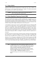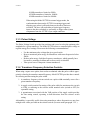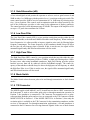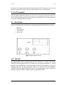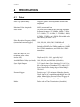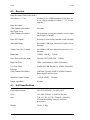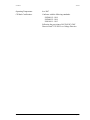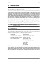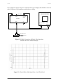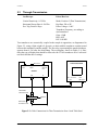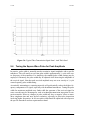
1
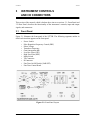
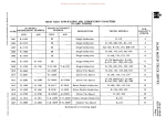
USER’S MANUAL Model 5077PR Part No. 910-202A In accordance with European Directive 2002/96/EC on Waste Electrical and Electronic Equipment, this symbol indicates that the product must not be disposed of as unsorted municipial waste, but should be collected separately. Refer to your local Olympus distributor for return and/or collection systems available in your country. Copyright 2000-2005 by Olympus NDT. All rights reserved. No part of this manual may be reproduced or transmitted in any form or by any means, electronic or mechanical, including photocopying, recording, or by any information storage and retrieval system, without the written permission of Olympus NDTTM, except where permitted by law. For information email: [email protected]. Other product names mentioned in this document may be trademarks of their respective companies, and are mentioned for identification purposes only. Printed in the United States of America. 910-202A 3/14/04 WARRANTY Damage in transit: The instrument should be examined immediately upon receipt for evidence of external or concealed damage. The carrier making delivery should be notified immediately of any such damage, since the carrier is normally liable for damage in shipment. Packing materials, waybills, and other such documentation should be preserved in order to establish claims. After such notification to the carrier, notify Olympus NDTTM of the circumstances so that we may assist in damage claims and in providing replacement equipment when necessary. Warranty: The 5077PR is guaranteed by Olympus NDT to be free from defects in materials and workmanship for a period of twelve months from date of shipment, provided that the equipment has been used in a proper manner as described in this instruction manual. Repairs or replacement, at Olympus NDT discretion, will be made without charge at its plant during this warranty period. Shipping expense to Olympus NDT is to be paid by the customer; shipping expense to return the repaired equipment will be paid by Olympus NDT. Olympus NDT reserves the right to modify its products without incurring the responsibility for modifying previously manufactured products. Olympus NDT does not assume any liability for the results of particular installations, as these circumstances are not in our control. Any attempt to repair, modify, or adjust the instrument other than as described in this manual will void the warranty and a charge will be made if repairs are required after such attempts. THE WARRANTIES SET FORTH HEREIN ARE EXCLUSIVE AND ARE IN LIEU OF ALL OTHER WARRANTIES WHETHER STATUTORY, EXPRESS OR IMPLIED (INCLUDING WARRANTIES OF MERCHANTABILITY AND FITNESS FOR A PARTICULAR PURPOSE, AND WARRANTIES ARISING FROM COURSE OF DEALING OR USAGE OR TRADE.) MODEL 5077PR i 3/14/04 910-202A This page intentionally left blank ii MODEL 5077PR 910-202A 3/14/04 TABLE OF CONTENTS 1 GENERAL DESCRIPTION .................................................................................... 2 UNPACKING AND INSPECTION ........................................................................ 3 INSTRUMENT CONTROLS AND I/O CONNECTORS..................................................................................... 3.1 Front Panel........................................................................................................ 3.1.1 Power Switch.......................................................................................... 3.1.2 Pulse Repetition Frequency Control (PRF)............................................ 3.1.3 Pulser Voltage ........................................................................................ 3.1.4 Transducer Frequency Selection Controls.............................................. 3.1.5 Gain/Attenuation (dB) ............................................................................ 3.1.6 Low Pass Filter ....................................................................................... 3-1 3-1 3-2 3-2 3-3 3-3 3-4 3-4 3.1.7 High Pass Filter ...................................................................................... 3.1.8 Mode Switch........................................................................................... 3.1.9 T/R Connector ........................................................................................ 3.1.10 R Connector.......................................................................................... 3.2 Rear Panel......................................................................................................... 3.2.1 RF OUT .................................................................................................. 3.2.2 EXT TRIG IN......................................................................................... 3.2.3 +SYNC OUT .......................................................................................... 4 SPECIFICATIONS .................................................................................................. 4.1 Pulser ................................................................................................................ 4.2 Receiver ............................................................................................................ 4.3 Unit Specifications............................................................................................ 5 OPERATIONS .......................................................................................................... 5.1 Oscilloscope Requirements .............................................................................. 5.2 Initial Set-up ..................................................................................................... 5.3 Through-Transmission...................................................................................... 5.4 Tuning the Square Wave Pulse for Peak Amplitude ........................................ 5.5 Voltage and Power Limitations of the Transducer ........................................... 6 TROUBLESHOOTING AND MAINTENANCE.................................................. 6.1 Basic Troubleshooting ...................................................................................... 6.2 Overcoming Electrical Noise Interference ....................................................... 6.3 Application Assistance ..................................................................................... 3-4 3-4 3-4 3-5 3-5 3-5 3-6 3-6 4-1 4-1 4-2 4-2 5-1 5-1 5-1 5-3 5-4 5-5 6-1 6-1 6-1 6-2 MODEL 5077PR 1-1 2-1 iii 3/14/04 910-202A This page intentionally left blank iv MODEL 5077PR 910-202A 1 3/14/04 GENERAL DESCRIPTION The Model 5077PR is an ultrasonic square wave pulser/receiver unit. When combined with an oscilloscope and appropriate transducers it provides a low-cost, ultrasonic measurement capability. Applications include: • Flaw Detection • Thickness Gaging • Sound Velocity Measurements (for computation of elastic constants) • Spectrum Analysis • Transducer Characterization • Other measurements used to monitor materials or processes The pulser section of this instrument generates square wave electric pulses of selectable width which, when applied to an ultrasonic transducer, are converted into short ultrasonic pulses. The ultrasonic pulses are received either by the transmitting transducer after partial or total reflection (pulse-echo method), or by a separate receiving transducer (pitch-andcatch or through-transmission methods). The voltage signals produced by the transducer, which represent the received ultrasonic pulses, are amplified by the receiver section. The amplified RF signal is available as output for display on an oscilloscope, or for processing by a Waveform digitizer or other instrumentation. MODEL 5077PR Page 1-1 3/14/04 910-202A This page intentionally left blank Page 1-2 MODEL 5077PR 910-202A 2 3/14/04 UNPACKING AND INSPECTION The 5077PR is designed and manufactured as a precision instrument, and under normal conditions it will provide long, trouble-free service. However, the user should inspect the instrument immediately upon receipt for damage incurred during shipment. Follow the procedure below to ensure the unit is functioning and is in good condition. 1. Unpack electronic unit and visually inspect it for physical damage. 2. At the cord connector on the rear panel, slide the transparent fuse cover to the left and verify that the exposed line voltage rating agrees with your voltage supply (100, 120, 220, or 240VAC). If it does not, pull out the small circuit board on which the number appears and find the correct voltage. Reinsert the board keeping the correct number visible and close the fuse cover. 3. Install the detachable line cord into the D Socket Connector. Plug the power cord into the line source and turn the Power Switch to On. The indicator light should be lit. Proceed as outlined in Section 5.2–Initial Setup. 4. The units are carefully inspected before shipment. Instruments failing to operate as described above are indicative of damage in transit. Proceed as outlined in the Warranty Section. MODEL 5077PR Page 2-1 3/14/04 910-202A This page intentionally left blank Page 2-2 MODEL 5077PR 910-202A 3 3/14/04 INSTRUMENT CONTROLS AND I/O CONNECTORS This section of the manual, which is broken down into two sections: 3.1–Front Panel and 3.2–Rear Panel, describes the functionality of the instrument’s controls, input and output signals, and connectors. 3.1 Front Panel Figure 3-1 illustrates the front panel of the 5077PR. The following segments outline in detail each item that appears on the front panel. • • • • • • • • • • • • Power Switch Pulse Repetition Frequency Control (PRF) Pulser Voltage Transducer Frequency Gain/Attenuation (dB) Low Pass Filter (LPF) High Pass Filter (HPF) Mode Switch T/R Connector R Connector Fine Tune On/Off Switch (VAR/SET) Fine Tune Control Knob Figure 3-1: Front Panel Layout MODEL 5077PR Page 3-1 3/14/04 910-202A 3.1.1 Power Switch With the 5077PR connected to appropriate line voltage (100, 120, 220, or 240VAC, 5060Hz) the power switch energizes the internal power supplies. The indicator light should be on when the power switch is in the ON position. Caution: Make sure that the voltage selection card located on the rear panel is in the appropriate voltage position. 3.1.2 Pulse Repetition Frequency Control (PRF) This control regulates the frequency at which excitation pulses are applied to the transducer through six crystal controlled calibrated settings from 100 to 5000Hz*. When measurements are being made in relatively thin material (up to 1 inch or 25mm) or in thicker materials that have high ultrasonic attenuation, the PRF may be set to the maximum value of 5KHz. This provides a bright oscilloscope trace at fast sweep rates. As the thickness of the test piece increases, the PRF should be decreased. When the PRF is excessive the baseline noise on the oscilloscope display will increase and appear to oscillate or vary with time. This is commonly referred to as “wrap around”. It is sometimes easy to confuse true scattering noise resulting from grain structure, or other scattering sources with noise induced by repetition rate. Unlike noise induced by the material, wrap around noise usually appears to vary with time while the transducer is held in a fixed position and greatly reduces or disappears completely when the repetition rate is decreased. In the EXT position, the internal pulse repetition frequency generator is disconnected and the 5077PR may be triggered externally by using the EXT TRIG IN CONNECTOR located on the rear panel (refer to Section 3.2.2). If a wider range of PRF control is desired, or if it is necessary to synchronize the 5077PR with other equipment, the PRF Control may be set to EXT and a suitable pulse generator may be connected to the EXT TRIG IN CONNECTOR located on the rear panel. The trigger pulse requirements are 2.4V (7V Max), and loading at this input is 1000pF capacitance in series with 10K ohms. Note: *Using high PRF rates with low frequency transducers may cause transducer damage because of the inherently high energy content of square wave pulses. Gray zones are imprinted on the front panel to indicate potentially undesirable combinations of PRF and transducer selections. The 5077PR also contains internal controls that provide protection against overexciting a transducer. However, if either the PRF or Transducer Frequency controls are positioned in the gray zone, then refer to the limitation guidelines below: Page 3-2 MODEL 5077PR 910-202A 3/14/04 0.1MHz transducer: limited to 500Hz 0.25MHz transducer: limited to 1000Hz 0.5MHz transducer: limited to 2000Hz When using the Model 5077PR in external trigger mode, the synchronization between the 5077PR’s incoming triggers and outgoing sync pulses is affected whenever the above limits are exceeded. The user will need either to limit trigger frequency inputs to the above schedule or, preferably, to trigger other system components from the 5077PR’s sync output connector. 3.1.3 Pulser Voltage The Pulser Voltage Switch provides four positions and is used to select the optimum pulse amplitude for a given transducer. The Model 5077PR selects a controlled pulse voltage to regulate energy level settings. Please note the following recommendations: • • • • Use the minimum pulse voltage that gives good results. Reserve maximum pulse energy for transducers with center frequencies below 5MHz. Reduce pulse energy for higher frequency transducers, which generally have less massive actuating elements and are more easily overloaded. Take special care of composite element transducers. 3.1.4 Transducer Frequency Selection Controls When using a square wave pulser, best results are obtained when the pulse width is appropriately related to the transducer natural frequency. Model 5077PR provides three controls for selecting and fine tuning the pulse width: 1. A transducer frequency selector switch sets a pulse width nominally correct for a given transducer frequency. 2. A toggle switch permits fine tuning of the pulse width for maximum echo (switch to VAR), or returning to the selector switch nominal value (switch to SET) for repeatable setting. 3. A potentiometer associated with the VAR position of the toggle switch provides the fine tuning control, operating in both directions from the selector switch setting. Adjustability is especially useful when using transducers whose frequencies are not close enough to the values provided on the selector switch. (See note under paragraph 3.2.2.) MODEL 5077PR Page 3-3 3/14/04 910-202A 3.1.5 Gain/Attenuation (dB) A fast action digital switch permits the operator to select a receiver gain between 0 and 59dB in either 1 or 10dB steps with the positive lever (+) positions on the gain switch. The same control provides 49dB of receiver attenuation in 1 or 10dB steps by selecting negative (-) lever positions. This control, used in conjunction with the vertical sensitivity control of the oscilloscope, provides a wide range in the adjustment of display sensitivity. The control provides a total adjustment range of 108dB. The output of the amplifier is linear up to +1V peak when terminated in 50 ohms. 3.1.6 Low Pass Filter The Low Pass Filter control (LPF) is a two position switch that provides either the full 35MHz bandwidth, or the indicated 10MHz selectable cutoff frequency. When working at lower frequencies it is often possible to improve signal to noise ratio by filtering higher frequency components. The center frequency of the transducer should always be below the low pass cut off frequency that is selected. If this is not the case, the signal will be attenuated significantly and Waveform distortion will also result. 3.1.7 High Pass Filter The High Pass Filter (HPF) control is a two position switch that provides either the complete bandwidth of the instrument (1KHz to 35MHz), or high pass filtering above 1MHz. In many cases when using broadband transducers, high pass filtering provides quicker baseline recovery than can be achieved with the broadband response. The center frequency of the transducer should always be above the high pass cut-off frequency to which the High Pass Filter is set. If this is not the case, the signal will be attenuated significantly and Waveform distortion will also result. 3.1.8 Mode Switch The Mode Switch selects between pulse-echo and through transmission or dual element modes. 3.1.9 T/R Connector The MODE toggle switch labeled 1 and 2, located between the two BNC connectors on the front panel, is used to select either pulse-echo or through-transmission operation. In Position 1, the transducer is connected to T/R Connector for transmit/receive or pulseecho operation. Both the pulser and receiver are connected to the T/R Connector with the MODE SWITCH in Position 1. If the MODE SWITCH is in Position 2, then only the excitation pulse is available at the T/R Connector for the transmitting transducer and the receiver is disconnected. For through-transmission applications, a second transducer is connected to the R Connector for receiving ultrasonic signals. In the case of dual element Page 3-4 MODEL 5077PR 910-202A 3/14/04 transducers, the transmit side should be connected to the T/R Connector, the receiver side should be connected to the R Connector and the Mode Switch set to Position 2. 3.1.10 R Connector With the MODE SWITCH in Position 2, the receiver is internally connected to the R connector. For through-transmission, or pitch-and-catch applications, the receiving transducer is, therefore, attached to the R Connector. 3.2 Rear Panel Figure 3-2 illustrates the layout of the rear panel that include the following connectors: • • • • RF OUT EXT TRIG IN +SYNC OUT Power Cord Figure 3-2: Rear Panel Layout 3.2.1 RF OUT The amplified RF signal is available at the RF OUT Connector. A 50 ohm coaxial cable should be connected from the RF OUT Connector to the required destination, i.e. vertical amplifier of the oscilloscope, or to the signal input of other data acquisition or signal conditioning equipment. The input impedance of the device connected to the cable should be 50 ohms. If a 50 ohm input is not provided on the user instrumentation, then a 50 ohm feed through terminator should be employed at the instrumentation input. MODEL 5077PR Page 3-5 3/14/04 910-202A 3.2.2 EXT TRIG IN With the PRF Control in the EXT position, the 5077PR may be triggered at rates up to 5000Hz* by an external source of +2.4 Volt pulses (7 Volts Max.). The EXT TRIG input circuit impedance is 1000pF capacitance in series with 10K ohms resistance for incoming amplitudes below 5V. Above 5 Volt, diode clipping reduces the 10K ohms to approximately 100 ohms. Minimum pulse width required is 50nS. Delay between EXT TRIG and Main Bang pulse is approximately 2uS. Note: *Using high PRF rates with low frequency transducers may cause transducer damage because of the inherently high energy content of square wave pulses. Gray zones are imprinted on the front panel to indicate potentially undesirable combinations of PRF and transducer selections. The 5077PR also contains internal controls that provide protection against overexciting a transducer. However, if either the PRF or Transducer Frequency controls are positioned in the gray zone, then refer to the limitation guidelines below: 0.1MHz transducer: limited to 500Hz 0.25MHz transducer: limited to 1000Hz 0.5MHz transducer: limited to 2000Hz rate When using the Model 5077PR in external trigger mode, the synchronization between the 5077PR’s incoming triggers and outgoing sync pulses is affected whenever the above limits are exceeded. The user will need either to limit trigger frequency inputs to the above schedule or, preferably, to trigger other system components from the 5077PR’s sync output connector. A few minutes spent observing the effect of each control on the signal presentation will be rewarding to the operator and will provide a better “feel” of the instrument. 3.2.3 +SYNC OUT The +SYNC Connector provides a synchronizing pulse +3.5V (Zout= 50 ohms), and is available for triggering the oscilloscope and for other equipment. It is capable of driving up to 26 standard TTL loads at 2.4 Volts. (See note under paragraph 3.2.2.) Page 3-6 MODEL 5077PR 910-202A 3/14/04 4 SPECIFICATIONS 4.1 Pulser Pulse Type (Main Bang): Negative Square Wave, adjustable duration and amplitude Maximum Pulse Amplitude: 400V (no external load) Pulse Width: 10 preset fixed widths for the following transducer frequencies/ranges: 15 - 20MHz, 10MHz, 7.5MHz, 5.0 - 6.0MHz, 3.5 - 4.0MHz, 2 - 2.25MHz, 1.0MHz, 0.5MHz, 0.25MHz, and 0.1MHz. Each width can be fine tuned by at least +/-25%. Pulse Repetition Frequency (PRF) (internal and external trigger): 100, 200, 500, 1000, 2000, 5000Hz for all transducers, except that maximum PRF is internally limited to: 2000Hz for 0.5MHz transducers, 1000Hz for 0.25MHz transducers, and 500Hz for 0.1MHz transducers. Pulse Rise and Fall Time (minimum pulse voltage and no load): 20ηS max (10% - 90%), typically 10ηS Available Pulse Voltage (no load): 100, 200, 300, and 400 Volts (Selectable) Sync Signal Output: 3.0V into 50 ohms. Pulse duration 0.5-10µS. Capable of driving up to 26 standard TTL Loads @2.4V. Sync Out precedes leading edge of Main Bang by 30-60ηS. External Trigger: Positive edge, 2.4V minimum. Min pulse duration 50ηS. Input is AC coupled through 1000pF into 10K ohms. Internal delay between External Trigger and leading edge of Main Bang is approximately 2µS. Mode: Pulse-echo or Thru Transmission (Selectable) MODEL 5077PR Page 4-1 3/14/04 4.2 910-202A Receiver Input Resistance (Pulse Echo Mode) (for echoes < +/- 5V): 50 ohms for 2 to 20MHz transducers 500 ohms for 0.1 to 1.0MHz transducers (echoes > +/-5V will be clipped) Input Resistance (Thru Transmission Mode): Max. Input Power (Thru Transmission Mode): 500 ohms The maximum average power that the receiver input can dissipate is 500mW. Phase (RF Output): Inverting or noninverting (internal switch selectable) Attenuator Range: 0 to 49dB in 1dB Steps Selected by Negative Lever Positions Voltage Gain (RL=50 ohms): 0 to 59dB in 1dB Steps Selected by Positive Lever Positions Bandwidth: 35MHz (-3dB) RL = 50 ohms Noise (Referred to the Input): Typically 30µV RMS (BW = 35MHz) High Pass Filter: 1KHz (Out Position) or 1MHz (Selectable) Low Pass Filter: 35MHz (Full BW Position) or 10MHz (Selectable) Isolation (Thru Transmission Mode): 53dB min (Typically 62dB) @ 10MHz (Isolation between pulser and receiver) Maximum Output Voltage: +1.0Vpk min (RL = 50 ohms) Output Impedance: 50 ohms 4.3 Unit Specifications Power Requirements: 100/120/220/240VAC, 50-60Hz, 10W Fuse: 1/8A (100/120)VAC: 1/16A(220/240)VAC Size: 7"W x 3.5"H x 10.1"D (178mmW x 89mmH x 256.4mmD including connector and knob projections) Weight: 5.0 lbs. (2.3Kg) Page 4-2 MODEL 5077PR 910-202A 3/14/04 Operating Temperature: 0 to 50°C CE Mark Certification: Conforms with the following standards: EN50081-2: 1994 EN50082-2: 1994 EN61010-1: 1995 Following the provisions of 89/336/EEC GMC Directive and 73/23/EEC Low Voltage Directive MODEL 5077PR Page 4-3 3/14/04 910-202A This page intentionally left blank Page 4-4 MODEL 5077PR 910-202A 3/14/04 5 OPERATIONS 5.1 Oscilloscope Requirements A wide variety of oscilloscopes may be used with the Model 5077PR Pulser/Receiver with good results. The final choice may be dictated by availability, cost, portability, anticipated applications, etc. In order to derive the full capabilities of the 5077PR, an oscilloscope with a 100MHz analog bandwidth and delayed sweep function is most favorable. For digital oscilloscopes, a minimum 5 times sampling rate is suggested (i.e., a 20MHz application would require a minimum 100MHz-sampler rate). To observe the excitation pulse (Main Bang) directly on the oscilloscope, a high voltage probe such as Tektronix P6009 or equivalent should be used. There are many oscilloscopes available that provide good performance. If you have any questions about selecting the best oscilloscope to suit your needs, please contact a Panametrics-NDTTM representative for assistance. Note: Settings for various transducers will differ, therefore use Section 5 primarily as a guide. 5.2 Initial Set-up After completing the unpacking procedure, connect the 5077PR to an oscilloscope and transducer as shown in Figure 5-1. Adjust the controls listed below: Oscilloscope Pulser/Receiver Vertical Sensitivity: 0.2V/Div Horizontal Sweep Rate: 1uS/Div Ext. Trig: Positive Slope Mode: Position 1 (Pulse Echo) Rep Rate: 2K or 5K Pulser Voltage = 100V Transducer Frequency, according to chosen transducer Gain: -10dB HPF: OUT LPF: Full BW When the initial set-up is complete, couple a transducer to a smooth steel or aluminum block about 1 inch thick. Use water, lightweight oil, glycerin or other suitable couplant to couple sound from the transducer to the sample. The first back echo should appear after the Main Bang or excitation pulse. After the first echo, a number of multiple echoes will be noticed. MODEL 5077PR Page 5-1 3/14/04 910-202A The oscillogram shown in Figure 5-2 illustrates the type of display that should be observed with a Videoscan V109 transducer and the above settings. Rear Panel +SYNC OUT EXT TRIG OSCILLOSCOPE RF SIGNAL OUT 5077PR T/R R Front Panel Zin = 50 ohms CH 1 CH 2 OR SYNC TRANSDUCER SAMPLE Figure 5-1: Cable Connections for Pulse-Echo Operation of Pulser/Receiver with Oscilloscope Amplitude (0-100%FSH) 25.0 0.0 -25.0 -50.0 0.00 5.00 Time µS Figure 5-2: Typical Pulse-Echo Signal from 1 inch Thick Steel Page 5-2 MODEL 5077PR 910-202A 5.3 3/14/04 Through-Transmission Oscilloscope Pulser/Receiver Vertical Sensitivity: 0.2V/Div Horizontal Sweep Rate: 0.5uS/Div Ext. Trig: Positive Slope Mode: Position 2 (Thru Transmission) Rep Rate: 2K or 5K Pulser Voltage = 100V Transducer Frequency, according to used transducer Gain: -15dB HPF: OUT LPF: Full BW Two transducers are acoustically coupled to the sample in opposition, as diagrammed in Figure 5-3, using a light weight oil, glycerin, or other suitable couplant to conduct sound between the transducers and the sample. The first echo, representing the sample thickness, appears about 4.5µS after the Main Bang. The oscillogram, shown in Figure 5-4, illustrates the type of display that should be observed with 2 V109 transducers on a 1 inch steel test block and the above settings. OSCILLOSCOPE Rear Panel +SYNC OUT EXT TRIG RF SIGNAL OUT 5077PR T/R R Front Panel Zin = 50 ohms CH 1 CH 2 OR SYNC TRANSMIT TRANSDUCER SAMPLE RECEIVER TRANSDUCER Figure 5-3: Cable Connections for Thru-Transmission from 1 inch Thick Steel MODEL 5077PR Page 5-3 3/14/04 910-202A Amplitude (0-100%FSH) 25.0 0.0 -25.0 -50.0 0.00 5.00 Time µS Figure 5-4: Typical Thru-Transmission Signal from 1 inch Thick Steel 5.4 Tuning the Square Wave Pulse for Peak Amplitude In practice, pulse width is normally tuned to maximize signal amplitude with a specific transducer. This will usually occur when pulse width is approximately ½ cycle at the center frequency of the transducer. For simplicity, the standard pulse width settings may be employed. Alternately, the pulse width may be adjusted while observing the amplitude of the received signal. Note that peak received amplitude may not occur exactly at ½ cycle center frequency pulse width setting. Acoustically attenuating or scattering materials will preferentially reduce the higher frequency components of a signal, especially with broadband transducers. Tuning the pulse width for maximum amplitude may further shift the spectrum of the received signal. In some cases this may be advantageous, such as in through transmission inspection of composite materials. However, changes in pulse width may have a negative effect on transducer ringdown time and near surface resolution, especially in pulse/echo inspections involving higher frequencies. In all cases pulse width should be optimized with respect to the specific transducer and test requirements at hand. Page 5-4 MODEL 5077PR 910-202A 5.5 3/14/04 Voltage and Power Limitations of the Transducer Ultrasonic transducers for NDT applications typically utilize piezoelectric elements whose energy output is related to applied voltage. In applications involving hard-to-penetrate materials, high pulse voltages are often desirable, but only to a point safely below levels that may cause transducer damage due to dielectric breakdown. Use of a ½ cycle square wave pulser also increases transducer output, but heating of the element due to increased average power can become significant at high pulse repetition rates. Care must be taken in selecting the operating voltage, pulse width, and repetition rates to prevent transducer damage. Many low frequency transducers (<5MHz) are fabricated from relatively thick elements that can tolerate excitation voltages greater than –400V peak. Unless specific electrical characteristics are known, transducers tuned with auxiliary inductors should not be excited with voltages greater than 400V. Transducers of frequencies greater than 5MHz typically have thinner elements, and specific manufacturer’s specifications on applied voltage should be consulted. A discussion of average power considerations is available for reference in the Technical Notes section of the Panametrics-NDTTM transducer catalog. Average power is dependent on the square wave voltage and pulse width, pulse repetition rate, and impedance of the transducer. Exceeding manufacturer’s pulse power recommendations for specific transducers may cause permanent transducer damage. MODEL 5077PR Page 5-5 3/14/04 910-202A This page intentionally left blank Page 5-6 MODEL 5077PR 910-202A 3/14/04 6 TROUBLESHOOTING AND MAINTENANCE 6.1 Basic Troubleshooting 1. Power LED does not illuminate: a. Confirm that the unit is properly connected to the appropriate voltage line source. b. Insure that the fuse, located on the back of the 5077PR, is in working order. 2. No signal displayed: a. Verify that the Pulser Receiver and external recording devices are properly connected. If using the 5077PR sync output, make sure the cable is connected from the Sync Out to the Ext Trig In of display device. Also verify that the PRF control is set to 100, 200, 500, 1K, 2K, or 5K. Adjust the trigger level of the recording device to obtain a signal. b. If the operator is using an External Trigger from an outside source, verify the cable connection from the 5077PR Ext Trig to the sync pulse of the source. Make sure the PRF position is set to Ext. c. Check the transducer cable continuity. d. Try using another transducer, if available. e. Clean the transducer and test material, and reapply couplant. 6.2 Overcoming Electrical Noise Interference Noise problems that can be encountered in using the 5077PR in benchtop, rack-mounted, or scanner bridge remote pulser/receiver situations can readily be overcome by following simple guidelines. In many cases, pulser/receivers are employed in electrically noisy environments, such as near scanner motor drivers or in proximity to electrical equipment, machinery, or lighting. Adequate shielding of the low-level RF (radio frequency) signals from the transducer and avoidance of ground loops are necessary to minimize sporadic noise spikes and high baseline noise levels. Most commonly, the transducer itself is shielded in a metal case. The integrity of electrostatic shielding depends on carrying the transducer case shield, search tube, and signal cable shields back to a dominant ground at the final or terminal instrumentation. Ground loops can be avoided by connecting the power cord of the Model 5077PR to the same terminal strip or outlet as the oscilloscope, auxiliary receiver, flaw detector, or data acquisition system. Electrical codes and safety practices should always be followed when supplying power to the instrument. MODEL 5077PR Page 6-1 3/14/04 910-202A The transducer case shield is typically connected via mating threads, a thread to ring UHF cable, or a search tube connector. Panametrics-NDTTM immersion connectors intended for immersion use have an integral ring that provides a more positive contact with the threaded connectors of transducers or search tubes, and these are available with double braided coaxial transmission lines. The transducer case, associated search tube, and UHF or BNC cable connectors should be isolated from grounds before the 5077PR instrument. Loose connections or inadvertent contact with grounds may result in large sporadic noise pulses on the RF signal. It is common practice to isolate the transducers and search tubes from scanner, bench, or rack grounds by using plastic fixtures. The chassis of the 5077PR is isolated from inadvertent grounding by plastic feet. The chassis should not be inadvertently connected to grounds by mechanical contact or installation, particularly if the 5077PR is being used as a remote pulser/receiver. The correct ground for the 5077PR is through the power cord. Inadvertent grounding can defeat electrostatic shielding, and the loop created by failure to have the dominant ground at the terminal instrumentation can cause high baseline noise levels. Coaxial cables are commonly employed for RF signal paths. In many cases standard coaxial cables are sufficient, however double braided coax cables, or double braided cables with outer metallic shields are much more effective in electrically noisy environments. The braided outer conductor of the coaxial cable, and the auxiliary metallic shield or integral drain wire, if employed, are brought back to the dominant ground at the terminal instrumentation. To be effective as electrostatic shields, these conductors must be grounded at only one end, preferably at the terminal instrumentation. 6.3 Application Assistance Panametrics-NDTTM is available to assist you with application problems that may occur. We encourage you to take advantage of our broad experience in ultrasonic techniques by contacting Panametrics-NDT staff directly. Panametrics-NDT E-mail: [email protected] Page 6-2 MODEL 5077PR