1
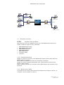
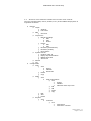
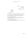
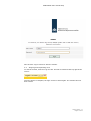
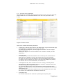
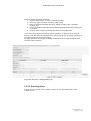
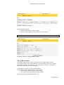
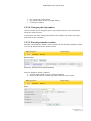
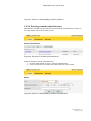
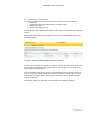
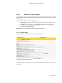
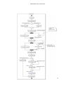
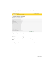
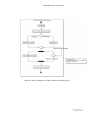
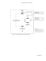
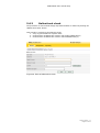
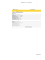
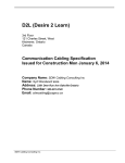
Software User
Manual
MARS2 - SHIP
MARS2 release
Version number
Date
Status
Authors
Owner
1.2
1.7
2014-06-03
Final
IBM
RWS
© 2014 RWS
SUM MARS2 User manual ship
Document versions:
Version
0.1
1.0
Date
13 December 2010
27 January 2011
Author
BSI, ILI
ILI
1.1
7 February 2011
GGI
1.2
1.3
29 June 2011
3 November 2011
FS
JWU
1.4
December 13, 2011
1.5
December 13, 2012
DDA
1.6
December 20, 2013
DDA
1.7
2014-06-03
DDA
Remark
First draft
Feedback
incorporated and
‘common’
sections added
Feedback from
RWS incorporated
RWS layout
Changes in
connection with
version 0.9.4
English
translation by The
Language Lab
Updates for
release 1.1
Updates for
release 1.1.4
section A1.1.10
Update for 1.2
and JSTD
Review
GGI
Style
EHE
JWU
Version number: 1.7
Pagina 2 of 60
SUM MARS2 User manual ship
CONTENTS
1
1.1
1.2
1.3
1.3.1
1.3.2
1.3.3
Introduction 6
About this document 6
System overview 6
Document overview 7
Purpose of the document 7
Document structure 7
Notes for the reader 7
2
REFERENCE DOCUMENTS 9
3
3.1
3.2
3.3
3.4
3.5
3.6
SOFTWARE SUMMARY 10
Software application 10
Software environment 10
Structure of the software interface and overview of the controls 11
Unanticipated occurrences and alternative states and modes of the controls 12
Security and protection of privacy 12
Assistance and reporting problems 12
4
4.1
4.1.1
4.2
4.3
4.4
ACCESS TO THE SOFTWARE 13
Initial use of the software 13
Installation and setup 13
Access control 13
Initiating a session 15
Stopping and suspending work 16
5
5.1
5.1.1
5.1.2
5.2
5.3
5.3.1
5.3.2
5.3.3
5.4
5.4.1
5.4.2
5.4.3
Ship system manual 17
Basic concepts 17
Hierarchical project structure 17
Trip structure 17
Overview of the possibilities 18
Configuration 19
Tables 19
Entry screens 20
Available options based on user role 20
Configuration 20
Managing users 20
Managing ship configurations 21
Managing locations 22
5.4.3.1 Viewing a location 22
Managing projects/contracts/parcels 23
Managing trips 25
5.4.5.1 Viewing a trip 25
Monitoring the dredging process 29
Preparations for dredging 30
5.5.1.1 Activation of a parcel 30
5.5.1.2 Activation of a parcel/ship 30
5.5.1.3 Activation of a ship configuration 30
Displaying process data 32
5.5.2.1 Process graph 33
5.4.4
5.4.5
5.5
5.5.1
5.5.2
Version number: 1.7
Pagina 3 of 60
SUM MARS2 User manual ship
5.6.2
5.6.3
5.6.4
5.7
5.7.1
5.7.2
5.7.3
5.8
5.5.2.2 Map 34
5.5.2.3 Process data 35
5.5.2.4 Alarms 36
Editing/adding process data 38
5.5.3.1 Entering manual soundings 38
5.5.3.2 Entering delays 39
5.5.3.3 Reset status 40
5.5.3.4 Changing the trip number 41
5.5.3.5 Entering remarks (weather) 41
5.5.3.6 Entering remarks (miscellaneous) 42
Performing a system check 43
Water trip procedure 44
5.6.1.1 Water trip 44
5.6.1.2 Reverse water trip 46
5.6.1.3 Empty ship determination 48
Theoretical empty ship determination 49
Ballast tank check 53
Suction head depth control 55
Offline database synchronisation 56
Preparation for offline synchronisation on shore 56
Offline synchronisation on the ship 57
Offline synchronisation on shore 57
Reporting 58
6
6.1
6.2
REMARKS 58
Abbreviations 58
Concepts 59
5.5.3
5.6
5.6.1
Appendix A. Password requirements 60
Version number: 1.7
Pagina 4 of 60
SUM MARS2 User manual ship
Version number: 1.7
Pagina 5 of 60
SUM MARS2 User manual ship
1
Introduction
1.1
About this document
This document describes the features and the use of the MARS2 Ship System by
various types of RWS and contractor users.
1.2
System overview
The MARS2 system is intended to facilitate the registration and visualisation of the
activities of dredging ships operating under contract with RWS.
This is accomplished through the installation of a special server on every dredging
ship (the Ship System) that reads in, stores and processes data from a number of
sensors on the ship.
Every Ship System is linked to a MARS2 Shore System. Certain basic data for every
ship is entered on this Shore System, such as ship configurations, projects,
contracts and parcels.
These data are synchronised with the Ship Systems, which are used by each
contractor to specify the current ship configuration and the parcel in which the ship
is operating.
The sensor data is continuously read in and processed throughout a dredging trip.
During processing, the data are also linked to the active ship configuration and the
parcel. All the data are then periodically sent to the Shore System.
The fact that the shore data can be linked to the ship configuration and the parcel
makes it possible to perform various checks and analyses as well as do things such
as monitoring the extent to which the contract conditions have been met.
The following diagram shows the MARS2 system components and their relationships
to each other.
Version number: 1.7
Pagina 6 of 60
SUM MARS2 User manual ship
Serial-IP
Convert0r
Operator ship
LAN ship
Data logger
Operator shore
LAN shore
Operator ship
MARS2-SHIP
MARS2-SHORE
Communication infrastructure(Sat, UMTS , GPRS)
Operator RWS
Operator maintenance
1.3
Document overview
1.3.1
Purpose of the document
This document serves as a guideline for the use of the MARS2 Ship System for a
number of different types of users, specifically:
·
·
·
·
·
·
·
RWS-MARS Support Group
RWS-MARS Project Leader
RWS-MARS Supervisor
RWS-MARS Validator
RWS-MARS Admin
Contractor Admin
Contractor
1.3.2 Document structure
Chapter 3 provides an overview of the MARS2 Ship System and its place within the
MARS2 system as a whole.
Next, chapter 4 explains how access to the software is arranged.
Chapter 5 provides a detailed explanation of the system features and how these
features can be utilised.
Finally, chapter 6 provides an overview of all the abbreviations and concepts in this
document.
1.3.3 Notes for the reader
A general overview of the system and its functionalities are provided in section 1.2,
in chapter 3 and in sections 5.1 and 5.2.
Version number: 1.7
Pagina 7 of 60
SUM MARS2 User manual ship
To familiarise yourself with the operation of the system, you can also read chapter 4
and section Fout! Verwijzingsbron niet gevonden..
Section 5.4 and beyond contain detailed instructions for the monitoring,
management and reporting functionalities.
Version number: 1.7
Pagina 8 of 60
SUM MARS2 User manual ship
2
REFERENCE DOCUMENTS
Abbreviated
name
[SCOM]
Fulle name
SCOM MARS2 Installatiehandleiding EN.doc
Version number: 1.7
Pagina 9 of 60
SUM MARS2 User manual ship
3
SOFTWARE SUMMARY
3.1
Software application
The MARS2 Ship System is primarily intended to monitor the dredging activities of
ships operating under contract with RWS.
This monitoring is achieved by reading in a number of sensors on the ship.
The measurement data from the sensors is saved and linked to the active ship
configuration and parcel/ship combination (‘parcel ship’), which makes it possible to
interpret and check the measurement values.
The basic data required for this (ship configurations, projects, contracts, parcels,
etc.) must be entered in advance on the MARS2 Shore System. This data is then
periodically sent to the MARS2 Ship System via the data link, keeping the systems
synchronised.
Once the basic data is available on the ship, the contractor must activate a ship
configuration, parcel and parcel ship to perform a dredging trip (hereafter: ‘trip’).
This makes it possible to perform the above-mentioned interpretation and checks.
The interpreted data can then be examined on the ship (see section 5.5.2).
From the ship it is also possible to add additional data to the trip (section 5.5.3) and
perform system checks (section 5.6).
In order to be able to analyse the measurement data originating from the ship on
shore as well, the data is also synchronised in the other direction.
See [SHORE_MANUAL].
3.2
Software environment
Both the MARS2 Shore System and the MARS2 Ship System can be accessed
remotely via a web browser. Supported web browsers are Firefox (version 3.5 or
higher) and Internet Explorer (version 8 or higher).
Version number: 1.7
Pagina 10 of 60
SUM MARS2 User manual ship
3.3
Structure of the software interface and overview of the controls
The user interface (tabs, menus, buttons, et al.) of the MARS2 Ship System is
organised as follows:
▼ Monitor
► Graph
○ Settings
○ Full screen
► Map
○ Overview
► Trip actions
○ Manual soundings
● Edit
● Add
● Delete
○ Delays
● Edit
● Add
○ Remarks (miscellaneous)
○ Remarks (weather)
○ Reset status
► System checks
○ Perform water trip
○ Empty ship determination
○ Ballast tank check
○ SHD check
► Alarms
► Log
▼ Configuration
► Trips
○ View
● Export
● Validate
● Recalculate
○ Delete
○ Copy
► Ships
○ View
● Ship configurations
■ View
□ Import
□ Validate
□ Calculate water trip norm
■ Edit
■ Add
■ Delete
■ Copy
○ Edit
○ Add
○ Delete
► Projects
○ View
● Contracts
■ View
□ Contractors
□ Contractor contacts
Version number: 1.7
Pagina 11 of 60
SUM MARS2 User manual ship
□
► Locations
○ View
► Contractors
► Users
○ View
► Synchronise
▼ Reporting
Parcels
♦ View
◊
◊
♦
♦
Parcel locations
Parcel ships
•
View
•
Activate
Activate
View trips for parcel
Each element in the structure above is discussed in detail starting in section 5.4.
3.4
Unanticipated occurrences and alternative states and modes of the controls
When an unanticipated error occurs while operating the system via the web
browser, this will be indicated by a specific error message on the screen.
3.5
Security and protection of privacy
Every person who uses the system must log in with their own user name and
password. This prevents RWS users and contractors from accessing and
manipulating each other's data.
3.6
Assistance and reporting problems
For assistance resolving problems and to report problems with the MARS2 system,
you can contact the RWS MARS Support Group.
Version number: 1.7
Pagina 12 of 60
SUM MARS2 User manual ship
4
ACCESS TO THE SOFTWARE
4.1
Initial use of the software
4.1.1 Installation and setup
Follow the instructions in the [SCOM] document to install the MARS2 Ship System.
4.2
Access control
Every user of the MARS2 system must have their own account. This can be created
by a MARS2 Admin or a Contractor Admin (see also section 5.4.1).
During creation of an account, a specific role is assigned to the user that enables
him or her to perform the necessary activities on the system. All parts of the system
that are not required to perform a certain role are made inaccessible.
The following user roles are distinguished within MARS2:
·
RWS MARS Support – the user with the most rights
·
RWS MARS Admin – for the management of RWS users
·
RWS MARS Project Leader – has a subset of the rights available to MARS
Support
·
RWS MARS Supervisor – has a subset of the rights available to Project Leader
·
RWS MARS Validator – rights similar to those of a Supervisor
·
Contractor Admin – for the management of contractor users
·
Contractor – operates ship
Additionally, there are various user rights for each type of installation (shore or
ship). On board the ship is only possible to make changes that are directly
connected with the dredging process; from a ship it is not possible to make changes
concerning trips or project locations, for example.
The following table indicates the rights for each type of user, broken down by task.
Version number: 1.7
Pagina 13 of 60
Users
Logging in
Contractors
Ships
Ship configurations
Locations
Projects /
Contracts /
Parcels
Trips
Monitor dredging
process
Check system
Add
View
Edit
Delete
On shore system
On ship system
Add
View
Edit
Delete
Add
View
Edit
Delete
Add
View
Edit
Delete
Add
View
Edit
Delete
Add
View
Edit
Delete
View trip data
Recalculate trip data
Copy trip data
Delete trip
Add trip
Change trip number
Export trip data
Validate trip
View process data
Edit process data
Add/edit manual soundings
Add/edit delays
Add/edit remarks
Reset system status
Water trip
TES determination
•
•
•
•
•
•
•
•
•
•
•
•
•
•
•
•
•
•
•
•
•
•
•
•
•
•
•
•
•
•
•
•
•
•
•
•
•
•
•
•
•
•
•
•
•
Validator
RWS MARS
Contractor
Admin
Supervisor
Contractor
RWS MARS
Project Leader
Admin
RWS MARS
Support
RWS MARS
RWS MARS
SUM MARS2 User manual ship
•
•
•
•
•
•
•
•
•
•
•
•
•
•
•
•
•
•
•
•
•
•
•
•
•
•
•
•
•
•
•
•
•
•
•
•
•
•
•
•
•
•
•
•
•
•
•
•
•
•
•
•
•
•
•
•
•
•
•
•
•
•
•
•
•
•
•
•
•
•
•
•
•
•
•
•
•
•
•
•
•
•
•
•
•
•
•
•
•
Version number: 1.7
Pagina 14 of 60
SUM MARS2 User manual ship
DB synchronisation
Ballast tank check
Suction head depth check
Offline synchronisation
•
•
•
•
•
•
•
•
•
•
•
During account creation a password is also specified; this must be entered when
logging in. The password is valid for a limited period of time, the length of which
depends on user's role.
ATTENTION: The user name and password for each account are strictly
personal and must NEVER be given to other users. Every user bears
personal responsibility for ensuring that this (often competitively valuable)
data does not fall into the hands of others.
When the password expires, the user must enter a new password. This occurs in a
separate screen that appears immediately after logging in.
The period of validity and password requirements are described in Appendix A.
4.3
Initiating a session
To initiate a user session on the MARS2 Ship System, all of the following are
required:
·
a user account (see section 4.2)
·
the URL via which the MARS2 Ship System is accessible
·
a PC with network access to the MARS2 Ship System, on which a supported web
browser is installed (see section 3.2)
To gain access to the system, the web browser must be started. Next, browse to the
URL of the MARS2 Ship System.
A login page now appears on which the details of the user account can be entered:
Version number: 1.7
Pagina 15 of 60
SUM MARS2 User manual ship
Now click the ‘log in’ button to start the session.
4.4
Stopping and suspending work
To end the session, click the ‘Log out’ link. This link is located at the top right of the
screen:
Once the logout is complete, the login screen is shown again. The session has now
been ended.
Version number: 1.7
Pagina 16 of 60
SUM MARS2 User manual ship
5
Ship system manual
5.1
Basic concepts
5.1.1
Hierarchical project structure
This section describes how the dredging operations are performed according to a
hierarchical project structure, with projects, contracts, parcels and contractors.
The basic principles of the project structure are:
· A project contains one or more contracts.
· A contract contains one or more parcels.
· A contract is linked to one or more contractors; a contractor can also be linked
to one or more contracts.
· A parcel is linked to one or more ships; a ship can also be linked to one or more
parcels.
· A parcel is linked to one or more locations; a location can also be linked to one
or more parcels. A calculation method and a calculation unit are defined for
every linked location.
· Certain parameters must be defined for parcel/ship combinations: these are
stored in the ‘parcel ship’ entity.
· During dredging activities, a parcel is selected on board the ship. During the
selection of the parcel, the project and contract are also visible. As of this
moment, the trips that are carried out are linked to this parcel.
·
A Project Leader can also be linked to a contract. A contract can have one or
more Project Leaders, and a Project Leader can have one or more contracts.
5.1.2
Trip structure
A ‘normal trip’ generally consists of a complete dredging cycle, e.g. loading, transit
loading, dumping, empty sailing. In addition, a trip can also consist of a system
check, such as a water trip or theoretical empty ship (TES) determination.
A normal trip is subdivided into sessions, of which there are two types:
·
loading session, in which material is loaded (e.g. suction or grab dredging)
·
dumping session, in which material is dumped (e.g. dumping or pumping
ashore)
A normal trip may consist of multiple loading sessions or multiple discharge
sessions. A normal trip always consists of at least one loading session and one
dumping session.
Version number: 1.7
Pagina 17 of 60
SUM MARS2 User manual ship
5.2
Overview of the possibilities
After logging into the MARS2 Ship System the following screen is shown. Note that
what is shown on the screen differs based on the user's role (see also section
5.3.3).
Figure 1: Monitor screen
This screen contains the following elements:
·
A status line, with the ship's name in the middle and a ‘Log out’ link at the right,
accompanied by a language icon in the form of a flag.
By clicking the language icon, the language for the session can be changed
(Dutch or English).
Clicking the ‘Log out’ link ensures that the user's session is ended (see also
section 4.4).
·
A ‘Monitor’ tab.
The (interpreted) measurement data for the current trip can be viewed here.
Data can also be added to the trip, and system checks can be performed.
For most user roles, this is the tab that is shown immediately after logging in.
If a different tab is selected (see below), this tab can be displayed by clicking
the ‘Monitor’ link. For more information, see section 5.5.
·
A ‘Management’ tab, which contains a menu for viewing, activating and/or
managing trips, ship configurations, projects, locations, contractors and users
and performing (offline) synchronisation.
For Contractor Admin users, this is the tab that is shown immediately after
logging in. If a different tab is selected, this tab can be displayed by clicking the
‘Management’ link.
The exact content of this menu depends on the role assigned to the user when
the account was created and is described in section 5.4.
·
A ‘Reporting’ tab.
The content of this tab can be shown by clicking the ‘Reporting’ link.
Version number: 1.7
Pagina 18 of 60
SUM MARS2 User manual ship
The reporting functionality is described in more detail in section 5.8.
5.3
Configuration
By clicking a menu item on the left side (e.g. ‘users’) a detail screen is opened at
the right. In the case of Management, this is usually a table (e.g. an overview of all
the users).
5.3.1
Tables
Many of the detail screens in MARS2 contain one or more tables, e.g. for the
management of trips and the management of locations. Every list in the MARS2
application has the same structure:
·
A number of buttons above the table.
These buttons are used to manipulate and view the elements in the table, e.g.
by adding or viewing them. Some buttons only become active once an element
in the table is selected or additional conditions have been met. These conditions
are explained in the description of each detail screen later in this chapter.
·
A row indicating the number of elements displayed and the total number of
elements, and to the far right a number of links for navigation between pages of
elements.
This row is only shown if the number of elements is greater than 20. When this
is the case, the first 20 elements of the table are shown by default.
To navigate to another part of the table, any of the links at the right side can be
clicked, where in each number represents a specific part of the table (e.g. ‘2’ for
elements 21 through 40). The ‘<<’, ‘<’, ‘>’ and ‘>>’ links jump to the beginning
of the table, the previous page, the next page and the end of the table
respectively.
·
A first row containing the column names.
The column names of the columns that can be used to sort the table are shown
as links (underlined); clicking one of these links sorts the table in descending
order based on the values in the corresponding column. Clicking a sortable
column a second time sorts the table in ascending order.
·
A row with fields that can be used for filtering.
By entering text or making a selection in one or more fields and clicking the
‘filter’ button, the displayed table is filtered based on the entered value or
combination of values. The following applies here:
o for filters on text fields, only those rows are shown for which the field values
contain the entered text (e.g. the filter ‘way’ for a ship's name also shows
the ship ‘Gateway’ if it appears in the table)
o for filters on numeric, selection or date fields, only those rows are shown for
which the field values match the entered/selected value exactly
By clicking the ‘all’ button the filter is turned off again and all the elements are
shown.
·
A number of rows containing the data for the elements.
Each of these rows can be selected, after which the buttons at the top of the
table can be used to perform an action, e.g. ‘View’.
In some cases it is also possible to select more than one row, e.g. for trips.
Any actions that are taken are then performed on all the rows at the same time.
·
A ‘filter’ and ‘all’ button at the bottom of the table for switching filtering on and
off respectively.
Version number: 1.7
Pagina 19 of 60
SUM MARS2 User manual ship
5.3.2
Entry screens
Entry screens are used for entering data (e.g. to create a new ship configuration on
shore). These normally contain input fields such as text boxes, drop-down lists,
checkboxes, etc.
Every input field is optional unless the field is marked with an asterisk (*); in that
case you must fill it in or make a selection.
Dates entered in date fields must have the format yyyy-mm-dd (e.g. 2010-12-16
for 16 December 2010).
Every entry screen also contains a ‘Save’ and ‘Cancel’ button. When the ‘Save’
button is clicked, the system will validate the input and any invalid data in the input
fields will be marked with a red border. An explanation of each error will also be
provided at the top of the screen.
Once all the data is valid, the entered information will be added to the system and
the system will return to the previous screen.
5.3.3
Available options based on user role
The table in section 4.2 shows which management activities can be performed by
each user role.
The following applies here:
·
When a user may not perform a certain activity based on their user role (e.g.
a ‘MARS Support’ user cannot delete a user), the button in question (‘delete’) is
not shown above the list.
·
When a user may not perform any activities at all within a certain category (e.g.
a ‘MARS Admin’ user cannot manage trips), the entire category is not shown on
the ‘Management’ tab at all.
5.4
Configuration
5.4.1
Managing users
Users are managed via the management screen, in the ‘users’ menu.
The only roles that can manage users are MARS Admin and Contractor Admin. These
roles have complete access for viewing, editing, adding and deleting RWS users and
contractor users respectively.
ATTENTION: A MARS Admin cannot manage contractor users, and a Contractor
Admin cannot manage RWS users.
Note that RWS users can also be created on the MARS2 Shore System; these are
then automatically synchronised with the ship.
Version number: 1.7
Pagina 20 of 60
SUM MARS2 User manual ship
Figure 2: Manage users screen
Figure 3: Adding/editing a user
MARS2 maintains a strict password policy; the applicable rules are set out in
Appendix A.
5.4.2
Managing ship configurations
On board the ship, ship configurations can only be activated and viewed, not added,
edited or deleted.
Figure 4: Overview of ship configurations
See section 5.5.1.3 for the procedure for activating a ship configuration.
Click the ‘view’ button to view the ship configuration. A ship configuration looks like
the example below.
Version number: 1.7
Pagina 21 of 60
SUM MARS2 User manual ship
Figure 5: Viewing a ship configuration
5.4.3
Managing locations
On board the ship, locations can only be viewed, not added, edited or deleted.
A location is used to indicate to the contractor where it must perform its dredging
work. A location consists of at least three coordinate pairs (each consisting of one
easting (X) and one northing (Y)) with which an area can be defined.
5.4.3.1 Viewing a location
Steps to view a location:
Select the ‘management’ tab and then ‘locations’ (Figure 6).
Figure 6: List of locations
Select the desired location and click the ‘view’ button (Figure 7).
Figure 7: Viewing a location
Click the ‘Back to list’ button to return to the list of locations.
Version number: 1.7
Pagina 22 of 60
SUM MARS2 User manual ship
5.4.4
Managing projects/contracts/parcels
On board the ship, projects can only be viewed; contracts and parcels cannot be
added, edited or deleted.
See section 5.5.1.1 for the procedure for activating contracts and parcels.
A list of projects can be shown by going to the Management screen and selecting
‘projects’.
Figure 8: List of projects
Click the ‘view’ button to view a project. This displays the project details.
Figure 9: Viewing a project
Via the project it is also possible to view the contract. To do so, select a contract
and click the ‘view’ button.
Version number: 1.7
Pagina 23 of 60
SUM MARS2 User manual ship
Figure 10: Viewing a contract
Via the contract it is also possible to view the parcel. To do so, select a parcel and
click the ‘view’ button.
Figure 11: Viewing a parcel
Version number: 1.7
Pagina 24 of 60
SUM MARS2 User manual ship
5.4.5
Managing trips
On board the ship it is not possible to edit trips; trips can only be viewed.
5.4.5.1 Viewing a trip
Click ‘Management’ and then ‘trips’ to open the list of all known trips. If necessary,
it is also possible to sort and filter by specific columns (see section 5.3.1).
Figure 12: Overview of trips
Now select a trip and click ‘view’ to see the details for a specific trip.
This button opens a new screen at the right with general data about the trip, a
number of buttons and, at the bottom, a set of tabs for all the trip details, such as
summaries, sessions and delays.
The ‘Back to list’ button takes you back to the list of all the trips.
Figure 13: Trip details
Version number: 1.7
Pagina 25 of 60
SUM MARS2 User manual ship
The various tabs are explained in more detail below.
‘Summary’ tab
This tab contains a number of extra data pertaining to the trip as a whole, such as
the parcel settings, the trip status and a number of (calculated) trip values such as
TDS, hopper volume loss, calculated volume sand, calculation unit and calculation
method.
Note that there may be more than one summary tab if multiple trips are viewed at
the same time. For this reason, the trip number is always placed after the name on
the tab.
‘Sessions’ tab
The ‘Sessions’ tab contains a table showing the details of all loading and dumping
sessions. The table can be sorted by location code, type of session, start time and
end time.
Version number: 1.7
Pagina 26 of 60
SUM MARS2 User manual ship
‘Graph’ tab
Besides the graph, the ‘Graph’ tab also contains two buttons.
The first button, ‘Settings’ opens a pop-up screen in which you can specify:
·
for which data items a line should be shown
·
whether the scale for the data item should be determined automatically
·
which minimum and maximum values should be used
·
which start and end times should be used (by default, this is the start and end
time of the entire trip)
The ‘Full screen’ button opens the graph screen to fill the entire width of the web
browser window. When this option is selected the Management menu will also no
longer be visible.
The browser's ‘Back’ button can be used to return to the other trip data and the
menu.
‘Map’ menu
This tab contains a map of the Netherlands in which the locations of all the sessions
are shown. You can zoom in to a specific section by clicking the grey rectangles on
the map. A blue line indicates the route taken during the trip.
When you zoom in on the map, the ‘Overview’ button appears above the map, along
with three selection buttons. Clicking the ‘Overview’ button zooms back out to the
view of the entire map. The selection buttons are used to select which locations
should be shown (no locations, only project locations or all active locations).
‘Remarks (miscellaneous)’ and ‘Remarks (weather)’ tabs
These tabs contain a list of all the miscellaneous and weather-related remarks
associated with the selected trip. Two additional buttons are shown here with which
a remark can be edited and added.
‘Delays’ tab
This tab contains an overview of all the delays that occurred during the trip.
The ‘Edit’ and ‘Add’ buttons can be used to manually edit and add delays
respectively.
‘Manual soundings’ tab
The bottom of this tab is a list of manual soundings that were performed during
the trip. Additional buttons are provided for adding, editing and deleting manual
soundings.
Version number: 1.7
Pagina 27 of 60
SUM MARS2 User manual ship
Above the list there are also a number of fields with totals. These totals are
calculated based on the manual soundings available in the list. If there are no
manual soundings available for a total, the value zero is shown.
‘System checks’ tab
This contains a list of all the system checks performed during the trip, and each is
accompanied by the date it was performed and whether it was passed (Yes/No).
Version number: 1.7
Pagina 28 of 60
SUM MARS2 User manual ship
5.5
Monitoring the dredging process
Monitoring the dredging process provides a display of the real-time values of various
dredging-related parameters.
These include (among others):
·
draft, trim and water displacement of the ship
·
Geographical position, speed, location and characteristics of the location
·
level, volume, mass, trim and density of material in the hoppers
·
calculated effective quantity sand or effective quantity dry solid
·
level, volume, mass, density of water in the ballast tanks
Monitoring of the dredging process is permitted for the following roles: Contractor,
Supervisor, Validator, Project Leader and MARS Support.
The process details are displayed on the monitor screen.
The size of the various panels can be adjusted by dragging the dividing lines
between the panels with the mouse.
The following section begins with a discussion of the steps that must be taken
before dredging begins, and then more detail is provided about monitoring the
dredging process.
Version number: 1.7
Pagina 29 of 60
SUM MARS2 User manual ship
5.5.1
Preparations for dredging
Before starting a trip in the dredging process, a number of settings must be made
and activated.
Selection and activation is permitted for all user roles, except for the roles MARS
Admin and Contractor Admin.
The data to be selected and activated are:
·
the parcel in which the work will be performed
·
the parcel ship to be used for the work (these are ship-specific settings for
the selected parcel)
·
the ship configuration (these are data concerning the geometry of the ship
and the sensors on board the ship)
The selected data only become active once the new trip is started. So when a trip is
currently in progress, it will first be completed with the same data that was active
when the trip began.
5.5.1.1 Activation of a parcel
A parcel can be activated via the management screen.
A parcel can only be activated if it has the ‘approved’ status.
Activate the desired parcel as follows:
·
go to the management screen and select the ‘projects’ menu
·
select the current project and click the ‘view’ button
·
select the current contract and click the ‘view’ button
·
Activate the desired parcel with the ‘activate’ button
Once these steps have been completed, the parcel ship can be activated straight
away (see the next section).
5.5.1.2 Activation of a parcel/ship
A parcel ship contains ship-specific settings for the parcel.
A parcel ship can only be activated when it has the ‘approved’ status.
Activate the desired parcel ship as follows:
·
Select the parcel activated in the previous section and click the ‘view’ button
·
Activate the desired parcel ship with the ‘activate’ button
5.5.1.3 Activation of a ship configuration
A ship configuration contains data concerning the geometry of the ship and the
sensors on board of the ship.
Version number: 1.7
Pagina 30 of 60
SUM MARS2 User manual ship
When there is only one approved ship configuration available, it is automatically
activated and manual activation is therefore unnecessary.
Activate the desired ship configuration as follows:
·
go to the management screen and select the ‘ship configuration’ menu
·
activate the desired ship configuration with the ‘activate’ button
Version number: 1.7
Pagina 31 of 60
SUM MARS2 User manual ship
5.5.2
Displaying process data
During the dredging process, process data is shown on the monitor screen.
The monitor screen is divided into a number of panels:
·
the process graph at the top left shows current measurement and trip data
in graphical form; here it is also possible to display a geographical map,
perform trip actions and start system checks
·
the alarm panel at the bottom left shows the current alarms
·
the process panel at the right shows current measurement and trip data in
numeric form
The status of the entire system is shown in the top right corner of the monitor
screen.
A colour is used to indicate the current status:
·
red – there is an active error; the system is not functioning properly
·
yellow – the system is functioning properly, but certain items have suspect
values (there are active alarms)
·
green – the system is functioning properly
Figure 14: Sample monitor screen, with the process graph (TDS, water
displacement, system status) at the top left, the alarm panel with a number of
active alarms at the bottom left and the process panel at the right.
Version number: 1.7
Pagina 32 of 60
SUM MARS2 User manual ship
5.5.2.1 Process graph
The ‘graph’ tab shows a graph of current and calculated process data.
Clicking the ‘settings’ button allows you to modify the set of data that is shown.
Figure 15: Process graph settings
The following settings can be changed for all data items shown in the graph:
·
show line – when ticked, the corresponding data item is shown
·
auto scale – when ticked, the vertical scale is automatically adapted to the
current minimum/maximum value for the data item
·
min/max – when auto scale is not ticked, you can specify the minimum and
maximum value of the vertical scale here
The ‘show minutes of hours’ setting is used to specify the horizontal time scale.
The ‘Full screen’ button makes the process graph larger so it fills the entire screen.
Select the monitor screen again to reduce the graph to the original size.
Version number: 1.7
Pagina 33 of 60
SUM MARS2 User manual ship
5.5.2.2 Map
The ‘map’ tab shows the data on a map. Maps can be displayed at two levels:
an overview map and a number of detailed maps.
The maps show the track of the ship during the current trip.
The overview map shows the entire area in which dredging activities are performed
for RWS (e.g. along the Dutch coastline).
Figure 16: Sample overview map
The detail maps can be shown by clicking the smaller grey-outlined rectangles in the
overview map. On the detail maps, locations and regions are shown in the form of
translucent blue areas. The location code is shown in the middle of every area.
Version number: 1.7
Pagina 34 of 60
SUM MARS2 User manual ship
Figure 17: Sample detail map
The following options can be selected when showing the detailed map:
·
‘show no locations’
·
‘show all active locations’ – shows all the locations, regardless of whether
they are active for the current project
·
‘show all project locations’ – only shows locations that are active in the
current project
5.5.2.3 Process data
The process panel on the right side of the monitor screen shows the current process
data in numeric form, organised in various data groups.
The following data groups are shown:
·
‘preference’ (optional) – details of a selectable set of data
·
‘trip’ – details of the current trip
·
‘TDS/m3’ – details of volumes/masses of material dredged during the
current trip
·
‘displacement’ – details of the water displacement of the ship and the
relevant sensors
·
‘hopper’ – details of the load in the hopper(s) and the relevant sensors
·
‘ballast tank’ – details of the volume in the ballast tank(s) and the relevant
sensors
·
‘data string’ – the raw measurement data provided to the system
Version number: 1.7
Pagina 35 of 60
SUM MARS2 User manual ship
The data shown in the ‘preference’ group is user selectable. The set of data shown
in this group can be configured on the management screen, in the ‘process panel’
menu.
This screen contains two columns of data items: data items that can be added (left
side) and data items that have already been added (right side). Clicking the [+] sign
adds the data item, and clicking the [-] sign removes the data item again. Finally,
confirm the data by clicking the ‘OK’ button.
5.5.2.4 Alarms
The alarm panel shows the current alarms.
When one or more alarms are active, the icon for the alarm shows its severity:
yellow is a warning and red is an error. Alarms are refreshed every five seconds.
The overall system status is linked to the severity of the active alarms:
·
when an error alarm is active, the system is in the ‘error’ state
·
when there is no error alarm active, but there is a warning alarm, the
system is in the ‘warning’ state
·
when there is no alarm active, the system is in the ‘functioning optimally’
state.
Version number: 1.7
Pagina 36 of 60
SUM MARS2 User manual ship
Possible alarms are:
Alarm
Error in sensor server.
CRC error in contractor data
string.
Formatting error in contractor
data string.
No data received.
Illegal value in sensor data
string.
Sensor value missing for sensor.
Communication error during
database synchronisation.
Database synchronisation error.
TES not performed.
TES is too old.
Calculation of X failed due to
missing data.
Calculation of X degraded due to
missing data.
Extrapolation from the
Carène/hopper/ballast tank
tables.
Location not found.
Hopper volume loss cannot be
determined accurately.
Unexpected contractor status.
Alternative TES determination
moment used.
There is no selectable ship
configuration.
There is no ship configuration
selected.
Ship configuration is invalid.
There is no active parcel
selected.
Possible solution
Check TCP port setting of the sensor server.
Check connection/cabling that supplies the data
string.
Check whether the content of the data string
matches IDD_SHIP specifications.
Check network connection configuration (IP
addresses, TCP port).
Check sensor and/or sensor's min/max value in
ship configuration.
Check whether the measurement value is being
sent and/or whether it is present in the ship
configuration.
Check ship-to-shore network connection.
Check ship-to-shore network connection.
Perform a TES.
Perform a TES.
Check whether sensors are functioning correctly.
Check whether sensors are functioning correctly.
Check proper operation of
Carène/hopper/ballast tank sensors.
Check whether loading/unloading is taking place
at the right location.
Make sure the ‘transit loading’ status lasts long
enough.
Check dredging status in data string.
Make sure there is sufficient water in the
hopper.
Make sure a selectable ship configuration is
available on shore and that this is ‘synchronised’
to the ship.
Select a ship configuration.
Check the ship configuration.
Select and activate a parcel.
Table 1: Overview of possible alarms
Version number: 1.7
Pagina 37 of 60
SUM MARS2 User manual ship
5.5.3
Editing/adding process data
Data can be edited and added during a trip on the ‘Trip actions’ tab of the process
panel on the monitor screen.
Editing and adding the data is permitted for all user roles, except MARS Admin and
Contractor Admin. Data that are linked to a trip can only be edited or deleted when
the status of the trip allows this. When the trip has already been validated, for
instance, delays can no longer be changed.
Figure 18: Overview of trip actions for editing/adding process data
5.5.3.1 Entering manual soundings
A manual sounding can be entered via the ‘Manual soundings’ button on the ‘Trip
actions’ tab of the monitor screen.
In addition to the conditions for editing a trip mentioned in section 5.5.3, a manual
sounding can also only be edited or deleted by the same user who created it.
Figure 19: Overview of existing manual soundings
Version number: 1.7
Pagina 38 of 60
SUM MARS2 User manual ship
Steps for adding a manual sounding:
1. click the ‘Add’ button to enter a manual sounding
2. select the type of manual sounding (sand or silt)
3. fill in the general sounding data (trip, hopper number, date, sounding
method, etc.)
4. enter the measurement data for the different types of soundings, starboard
or portside.
5. click the ‘Save’ button to confirm and save the sounding data
In the case of an empty sounding or a level sounding, in addition to the general
data you can also enter an estimate of the remaining silt (for an empty sounding) or
a silt percentage (for a level sounding).
For type sand a full and empty sounding can be entered, for type silt also a level
sounding can be entered.
Figure 20: Screen for adding/editing silt
5.5.3.2 Entering delays
A delay can be entered via the ‘Delays’ button on the ‘Trip actions’ tab of the
monitor screen.
Version number: 1.7
Pagina 39 of 60
SUM MARS2 User manual ship
Figure 21: Overview of delays
Steps for adding a delay:
1. click the ‘Add’ button to enter a delay
2. enter the delay data and confirm with the ‘Save’ button
ATTENTION: The time span of the delay must fall within the trip.
Figure 22: Screen for adding/editing a delay
5.5.3.3 Reset status
The system status of the current trip can be reset to empty sailing with the
‘Reset status’ button. The system status reset is a procedure that is only used in
exceptional situations, such as when – for one reason or another – the system
status does not match the actual situation.
The button is only active under certain conditions.
The conditions under which this button is active are:
·
the contractor status must be ‘empty sailing’
·
the system status must NOT be ‘empty sailing’
The consequences of clicking this button are:
Version number: 1.7
Pagina 40 of 60
SUM MARS2 User manual ship
·
·
·
the current trip is interrupted
the system status returns to ‘empty sailing’
a new trip is started
5.5.3.4 Changing the trip number
The trip number can be changed via the ‘Trip number’ button on the ‘Trip actions’
tab of the monitor screen.
In contrast to the other changes described in this chapter, this action can only be
performed by the contractor.
5.5.3.5 Entering remarks (weather)
Remarks concerning the weather can be entered via the ‘Remarks (weather)’ button
on the ‘Trip actions’ tab of the monitor screen.
Figure 23: Overview of remarks (weather)
Steps for adding a remark (weather):
1. click the ‘Add’ button to enter a remark (weather)
2. enter the data for the remark and confirm with the ‘Save’ button
Version number: 1.7
Pagina 41 of 60
SUM MARS2 User manual ship
Figure 24: Screen for editing/adding remarks (weather)
5.5.3.6 Entering remarks (miscellaneous)
Miscellaneous remarks can be entered via the ‘Remarks (miscellaneous)’ button on
the ‘Trip actions’ tab of the monitor screen.
Figure 25: Overview of remarks (miscellaneous)
Steps for adding a remark (miscellaneous):
1. click the ‘Add’ button to enter a remark (miscellaneous)
2. enter the data for the remark and confirm with the ‘Save’ button
Figure 26: Screen for editing/adding remarks (miscellaneous)
Version number: 1.7
Pagina 42 of 60
SUM MARS2 User manual ship
5.6
Performing a system check
A number of system checks can be performed on board the ship, specifically:
·
water trip
·
theoretical empty ship determination (hereafter: TES)
·
ballast tank check
·
suction head depth control
System checks can be viewed and started on the ‘System checks’ tab of the monitor
screen.
Performing system checks is permitted for all user roles, except MARS Admin and
Contractor Admin.
Figure 27: Screen for editing/adding remarks (weather)
A system check procedure consists of a number of steps. The first step is always the
entry of general data about the system check. In the last step, an overview of the
system check is always shown.
The intermediate steps can be carried out automatically when a certain criterion is
met (e.g. when the inside/outside level difference reaches a certain value), but can
also be manual steps in which the contractor must enter data or in which results
must be confirmed.
The system checks are discussed in more detail in the following sections.
Version number: 1.7
Pagina 43 of 60
SUM MARS2 User manual ship
5.6.1
Water trip procedure
A water trip procedure is started by clicking the ‘Perform water trip’ button. A water
trip procedure can only be started when an empty ship determination has just been
performed.
This procedure consists of the following parts:
·
a water trip, in which the hoppers are filled with water; this results in the
suction report
·
optionally a reverse water trip, in which the hoppers are pumped empty;
this results in the reverse water trip report
·
an empty ship determination
The ultimate result of all these parts is the water trip report.
5.6.1.1 Water trip
The first step of a water trip is to fill in the general data.
Figure 28: Starting a water trip
The figure below provides an overview of the activities that comprise the water trip
procedure.
Version number: 1.7
Pagina 44 of 60
SUM MARS2 User manual ship
Version number: 1.7
Pagina 45 of 60
SUM MARS2 User manual ship
Figure 29: Activity diagram for water trip procedure, including (in blue) the reverse
water trip and TES determination
Figure 30: Progress of water trip
5.6.1.2 Reverse water trip
After performing the water trip within the water trip procedure, the option is given
to complete the water trip with a TES determination or to perform a reverse water
trip.
The figure below provides an overview of the activities that comprise the reverse
water trip.
Version number: 1.7
Pagina 46 of 60
SUM MARS2 User manual ship
Version number: 1.7
Pagina 47 of 60
SUM MARS2 User manual ship
Figure 31: Activity diagram for reverse water trip
Figure 32: Progress of reverse water trip
5.6.1.3 Empty ship determination
After both the ‘normal’ water trip and the reverse water trip, a TES determination is
performed.
The figure below provides an overview of the activities that comprise the TES
determination within the water trip procedure.
Version number: 1.7
Pagina 48 of 60
SUM MARS2 User manual ship
Figure 33: Activity diagram of TES determination within water trip
5.6.2
Theoretical empty ship determination
The procedure for a theoretical empty ship determination is started by clicking the
‘Determine empty ship’ button.
This procedure consists of the following steps:
1. entry of general data for the TES procedure
2. verification of the initial conditions for TES
3. check of conditions within a certain amount of time and TES determination
4. displaying and confirming the calculated theoretical empty ship mass
Version number: 1.7
Pagina 49 of 60
SUM MARS2 User manual ship
Figure 34: Start of TES procedure
Figure 35: Progress of TES determination
The figures below show the various steps of the TES procedure in more detail.
Version number: 1.7
Pagina 50 of 60
SUM MARS2 User manual ship
Figure 36: Activity diagram for initial conditions for starting TES
Version number: 1.7
Pagina 51 of 60
SUM MARS2 User manual ship
Figure 37: Activity diagram for TES determination
Version number: 1.7
Pagina 52 of 60
SUM MARS2 User manual ship
5.6.3
Ballast tank check
The procedure for a theoretical empty ship determination is started by clicking the
‘Ballast tank check’ button.
This procedure consists of the following steps:
1. entry of general data for system check
2. measurement of ballast tank volume with empty ballast tank(s)
3. measurement of ballast tank volume with full ballast tank(s)
Figure 38: Start of ballast tank check
Version number: 1.7
Pagina 53 of 60
SUM MARS2 User manual ship
Figure 39: Result of ballast tank check
Version number: 1.7
Pagina 54 of 60
SUM MARS2 User manual ship
5.6.4
Suction head depth control
The procedure for a suction head depth control is started by clicking the ‘SHD’
button.
This procedure consists of the following steps:
1. entry of general data for suction head depth check, such as the
characteristics of the sensor and the measurement value of the on-deck
calibration
2. entry of measurement value when the suction head is at a certain depth;
when the ‘Calculate’ button is clicked the system uses this data to calculate
the corresponding depth of the calibration sensor and compares this to the
depth supplied in the data string
3. the previous step can be performed for various depths
Figure 40: Start of suction head depth check
Version number: 1.7
Pagina 55 of 60
SUM MARS2 User manual ship
Figure 41: Entry of measurement value for calibration sensor
5.7
Offline database synchronisation
The MARS2 system performs automatic online synchronisation of the data in the
ship systems and shore system at regular intervals via the network. In addition, the
MARS2 System also offers the option to perform offline database synchronisation.
This offline synchronisation procedure consists of the following steps:
1. An offline synchronisation is started on shore. The result is a file (data file A)
with basic data for a specific ship, which is placed on a USB stick for
instance.
2. On the ship, the file (data file A) is read in from the USB stick. The system
on the ship then generates a file with trip data (data file B) for the shore
system, which is written back to the USB stick.
3. Once on shore, the file from the ship (data file B) is read in and processed.
The generation, import and export of these synchronisation files is only permitted
for user role MARS Support.
5.7.1
Preparation for offline synchronisation on
shore
The first step in the offline synchronisation is the creation of data file A on the shore
system. To do this go to the management screen and select the ‘synchronize’ menu.
Under ‘1 - Create database synchronization file’, select the name of the ship and
click the OK button. At this point data file A can be placed on a USB stick.
Version number: 1.7
Pagina 56 of 60
SUM MARS2 User manual ship
Figure 42: Creation of data file A on the shore system
Note that it is also possible to skip this step. In that case all the trip data from the
ship are saved in data file B (see below) and the basic data on the ship (ship,
project and user data) will not be updated. This is therefore usually undesirable and
is only intended for use in exceptional situations!
5.7.2
Offline synchronisation on the ship
The second step in the offline synchronisation is the processing of data file A and the
generation of data file B on the ship system.
On the ship, data file A can be imported via the management screen, by selecting
menu option ‘Synchronize’. Click the ‘Browse’ button to select data file A. If this file
could not be created (see the previous section), click ‘OK’ straight away.
Figure 43: Processing data file A, generating data file B on the ship system
Once the ‘OK’ button is clicked, the offline database synchronisation file (data file A)
is processed and a file with ship data (data file B) is created. The web browser will
then ask whether you want to save this file. A USB stick can be used for this
purpose.
5.7.3
Offline synchronisation on shore
The third step in the offline synchronisation is the import of the data created on the
ship (data file B) to the shore system.
Version number: 1.7
Pagina 57 of 60
SUM MARS2 User manual ship
To do this go to the management screen and select the ‘Synchronize’ menu. Under
‘2 - Upload ship database’, select data file B via the ‘Browse’ button and click the OK
button (see Figure 42).
5.8
Reporting
Reports can be created via the reporting screen, which is shown by clicking the
‘Reporting’ tab.
All user roles have permission to create reports on the ship.
Figure 44: Example of overview reports on the reporting screen
Steps for creating a report:
1. Select a predefined report from the menu at the left (e.g. the ‘Trip report’).
2. Via the dialogue in the middle of the screen, select the ship for which the
report should be created.
3. Select the other parameters (these vary by report) and confirm with OK.
The report is displayed.
4. (Optional) Click one of the icons to export the report to Microsoft Excel
format, Microsoft Word format or PDF.
6
REMARKS
6.1
Abbreviations
The table below contains a list of the abbreviations used in this document and their
definitions.
Abbreviation
MARS2
DS
SUM
TDS
Definition
Monitoring and Registration System version 2
Density Sand
Software User Manual
Tons Dry Solid
Version number: 1.7
Pagina 58 of 60
SUM MARS2 User manual ship
TES
SHD
Theoretical Empty Ship (determination)
Suction Head Depth
6.2
Concepts
The table below contains a list of the concepts used in this document and their
definitions.
Concept
Contract
Parcel
Parcel location
Parcel ship
Project
Ship configuration
Sensor
Software
Definition
Relation consisting of contractors, contractor contacts and
parcels for a certain period of time (the contract duration).
Collection of parcel locations, parcel ships, tender quantities
and constants required to be able to perform calculations.
Relation consisting of a specific location within a parcel,
along with the calculation method (loaded/discharged) and
calculation unit (TDS/m3) that must be employed for this
parcel/location combination.
Relation of a specific ship to a parcel, along with specific
tolerances that must be employed for this parcel/ship
combination.
Collection of associated contracts.
Collection of dimensions that are required in order to be
able to interpret the measurement values from the sensors
on the ship. Examples of these dimensions are hopper
volumes, ship measurements and sensor locations.
Device that measures a certain parameter on the ship, such
as height, pressure or position.
Generic term for that encompasses both the operating
system and application programs.
Version number: 1.7
Pagina 59 of 60
SUM MARS2 User manual ship
APPENDIX A. PASSWORD REQUIREMENTS
The requirements established for user names and passwords within MARS2 are as
follows:
·
role: Contractor, Contractor Admin:
o min. password length is eight characters
o password never expires
o password must include at least one numeral and one capital letter
o max. number of failed log in attempts: unlimited
·
role: MARS Support, MARS Project Leader, MARS Supervisor, MARS Validator:
o min. password length is eight characters
o period of validity is 90 days
o password must contain a combination of numerals, capital letters, lower
case letters and punctuation marks
o the new password may not be the same as any of the last twelve
passwords
o max. number of failed log in attempts: 5
·
role: MARS Admin:
o min. password length is fifteen characters
o period of validity is 30 days
o password must contain a combination of numerals, capital letters, lower
case letters and punctuation marks
o the new password may not be the same as any of the last twelve
passwords
o max. number of failed log in attempts: 5
Version number: 1.7
Pagina 60 of 60