1
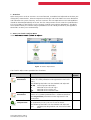
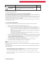
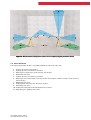
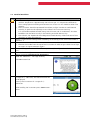
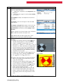
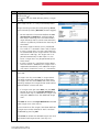
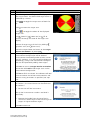
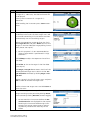
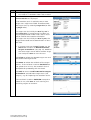
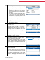
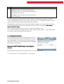
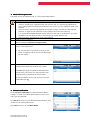
Leica HDS Check & Adjust – User Manual
Contents
1
Overview ......................................................................................................................................... 2
2
Access to Check & Adjust Menu ............................................................................................. 2
3
Check Angular Parameters ........................................................................................................ 3
3.1 Measurement Configuration ............................................................................................................ 3
3.2 Basic Workflow ................................................................................................................................... 4
3.3 Detailed Workflow ............................................................................................................................. 5
4
Set Range Parameters .............................................................................................................. 12
5
Check Tilt Compensator ........................................................................................................... 13
6
Current Calibration ................................................................................................................... 13
Leica Geosystems AG
Heinrich-Wild-Strasse
CH-9435 Heerbrugg
Switzerland
Leica HDS Check & Adjust
User Manual (Version 1.0)
www.leica-geosystems.com
1 Overview
Leica Geosystems 3D laser scanners are manufactured, assembled and adjusted to the best possible quality. Nevertheless, extreme temperature changes and hard shocks can cause deviations
and influence the system accuracy. 3D laser scanners that are exposed to such hard conditions
should be checked periodically to ensure that the measurement results meet the specifications.
This can be done in the field by running through specific measurement procedures. The deviations determined by the Check & Adjust procedures can be stored permanently and applied as
corrections to every scan automatically.
2 Access to Check & Adjust Menu
Select Main Menu:
Menu: Tools…\
Tools…\ Check & Adjust…
Figure 1: Check & Adjust Menu
The Check & Adjust menu provides four functions:
Function
Check Angular
Parameters
Set Range
Parameters
Check Tilt
Compensator
Leica HDS Check & Adjust
User Manual (Version 1.0)
Description
The angular system parameters can be determined by
means of a field procedure and registered in the instrument.
The following deviations can be checked and adjusted:
λ1, λ2 Laser alignment deviations
µ
Deviation of the line of sight
ε
Deviation of the tilting axis
∆el
Deviation of the vertical index
In case the distance measuring unit has been checked by
means of a standard procedure on a reference baseline,
the range offset parameter can be registered in the
instrument.
The tilt sensor can be checked and its parameters can
be updated by an easy-to-use tilt sensor check.
The following deviations can be checked and adjusted:
L, T
Compensator longitudinal and transversal index
error
Refer to
section
3
4
5
Function
Current
Calibration
Description
The currently stored corrections determined in Check &
Adjust are displayed and can be reset to the factorydefault values.
Refer to
section
6
3 Check Angular Parameters
The angular system parameters are checked in a guided field procedure.
In this field procedure the instrument has to be set up on two different stations. From both stations at least five Black&White targets will be scanned in both faces.
After collecting all measurement data the software will automatically check the target scans and
evaluate the measurement data. Finally the determined angular deviations will be displayed and
can be registered in the instrument as corrections.
In order to ensure a thorough parameter check the measurement configuration has to fulfill certain configuration criteria.
3.1 Measurement Configuration
The measurement configuration of the angular parameter check has to meet six criteria:
1. No target must be scanned in a distance shorter than 2.5 m.
2. There has to be at least one target behind and close to each station near horizon, i.e.:
• Next to each station a target has to be positioned in a minimal distance of 2.5 m
and in a maximum distance of ds/3, where ds is the distance between both stations.
• These targets have to be positioned within a maximum angle of 15° above or beneath the horizontal plane.
• These targets have to be positioned in a horizontal direction of 135° up to 225°
relative to the direction to the farer station.
3. There has to be at least one target in a distance of at least ds from both stations, where
ds is the distance between both stations. It has to be positioned in a maximum angle of
5° above or beneath the horizontal plane.
4. There has to be at least one target in a height of at least 18 m above one station in a
minimum angle of 73° above the horizontal plane.
5. The distance between both stations ds has to be equal or greater than 20 m.
6. At least five targets in five different positions are necessary.
Figure 2 visualizes the measurement configuration criteria 2 to 6.
In case all six configuration criteria are met all angular deviations can be checked by evaluating
the target scans.
In case one or more criteria are not met only a subset of the angular deviations will be considered and checked.
Always consider the laser beam’s angle of incidence on the target plane when positioning
the targets and defining the station positions!
The angle of incidence should never be less than 60°, while 90° is the optimum angle.
The minimum number of targets is five. Nevertheless it is recommended to use six to eight
targets for the check.
Leica HDS Check & Adjust
User Manual (Version 1.0)
Figure 2: Measurement
Measurement configuration criteria for a complete angular parameter check
3.2 Basic Workflow
The angular parameter check is a guided procedure. The basic steps are:
1.
2.
3.
4.
5.
6.
Setting up at least five targets.
Setting up the instrument on station 1.
Defining the target scans and scanning the targets.
Reviewing the scans.
Setting up the instrument on station 2.
Defining at least two target scans out of the five targets used on station 1 and scanning
these targets.
7. Reviewing the scans.
8. Automatically scanning the remaining targets.
9. Reviewing the scans.
10. Automatic evaluation and calculation of the results.
11. Registering or skipping the results.
Leica HDS Check & Adjust
User Manual (Version 1.0)
3.3 Detailed Workflow
Step
1
2
3
4
5
Description
Before starting the measurements the instrument has to become acclimatised to the
ambient temperature. Approximately two minutes per 1°C temperature difference
from storage place to working environment but at least 15 min should be taken into
account.
The instrument should be protected from direct sunlight in order to avoid thermal
warming in general and especially on one side of the instrument housing.
It is also recommended to avoid strong heat shimmer and air turbulences. The best
conditions can be found usually in the morning and with overcast sky.
The tribrach, the tripod and the underground should be very stable and secure from
vibrations or other disturbances.
Define a measurement configuration according to the configuration criteria described in
section 3.1.
Set up the instrument on station 1.
Remove the handle from the top of the instrument in order to get a clear line of sight
to targets in higher elevation angles!
Set up the targets in at least five different positions (cf. configuration criteria in section
3.1).
Tools / Check & Adjust Menu
Select the option Check Angular Parameters.
Read the “Welcome…” message carefully.
Click OK to continue.
6
In case the instrument has not been levelled up in
a range of +/- 20 arcsec, the electronic level will
be displayed.
Level up the instrument in a range of +/20 arcsec.
After levelling the instrument press Cont to continue.
Leica HDS Check & Adjust
User Manual (Version 1.0)
Step
7
Description
Define the target scans on station 1. Each target
scan has to be defined by…
1. … specifying a target ID in the Target ID input
field and…
2. … aiming at the target in the live video (PickT,
see step 8).
Click ChkExp to adjust the exposure time of the
live video.
Click PickT to aim at the target in the live video
(see step 8).
Click Page or Target List to access the list of the
already defined target scans. Return to the Target Definition interface by clicking Page or Target Def.
Select a target in the list of target scans and press
Del in order to remove the target scan.
8
After defining one or more target scans, click
Cont to start scanning the defined targets.
Navigate in the live video by using the following
functions:
• Enable the rotation wheel by clicking . The
rotation wheel appears in the center of the
screen. It provides arrow buttons for navigating up (), down (), to the left () or to
the right (). After activating an arrow button
the instrument or the mirror respectively will
move in the appropriate direction continuously. The movement can be stopped by clicking
anywhere on the screen.
• Enable the seek mode by clicking . The camera will point to any position clicked before.
• Use
(zoom-in) or
(zoom-out).
For picking the target there are three possibilities:
• Point at the target by the crosshair, e.g. by
using the seek mode.
• Activate the pick mode by clicking
as soon
as the target is in the field of view of the
camera and click roughly on the target center.
• Activate the fence mode by clicking
and
draw a fence around the target.
The target will now roughly be scanned and
the scan will be displayed in the target scan
viewer. Activate the pick mode by clicking
and roughly click on the target center in the
scan.
In order to confirm the picked direction to the
Leica HDS Check & Adjust
User Manual (Version 1.0)
Live video:
Scan viewer:
Step
9
Description
target and to return to the Target Definition interface click .
For leaving the live video without picking a target
click .
Scanning the defined targets and determining
their target centers is a fully automated process.
Target scanning can be paused by clicking Pause
and resumed by clicking Resume (button toggles).
10
Do not touch the instrument before the Target Results on Station 1 are displayed on
the screen! Touching the instrument before
might influence the tilt sensor measurements
and can significantly influence the accuracy of
the check!
For every target a coarse scan is performed
first. Then it is scanned in face I and in face II.
In case a target scan in at least one face fails
or the deviation of the target centers of face I
and face II is too high, this target scan is repeated automatically in both faces. In rare
cases a target scan may be performed up to
three times.
In case a target in a significant height above
the instrument is detected, this target scan is
repeated automatically. The additional target
scan will by listed with suffix “_2” afterwards.
After all defined targets were scanned the results
are listed.
If a target scan has status OK, its target center
has been successfully determined in both faces.
If a target scan has status Bad, even after three
scanning attempts the target center could not be
determined for at least one face.
If a target scan got status Bad, use the Add
button to return to the Target Definition interface (see step 7). Redefine this target scan
and press Cont to start the redefined target
scan.
Click Add to return to Target Definition and add
more target scans (see step 7).
In case more than five targets have been defined
a target scan can be selected in the list and can
be deleted by pressing Del.
Click View to review the selected target scan and
the determined target center (see step 11).
Leica HDS Check & Adjust
User Manual (Version 1.0)
Step
11
Description
Click Cont to finish target scanning on station 1.
After clicking View the target scan is displayed in
the target viewer. The determined target center is
indicated by a vertex.
Click
es.
Click
/
to toggle the target scans of both fac-
to rotate the target scan.
Click / to toggle the colors of the displayed
target scan.
Use
(zoom-in),
(zoom-out) or
(fit to
screen) to change the scale of the target scan
display.
Browse all target scans of the list by clicking
(previous scan) and
(next scan).
12
Leave the target viewer and return to the Target
Results on Station 1 by clicking .
After target scanning on station 1 is finished, the
measurement configuration will be checked.
In case one or more configuration criteria are not
met (cf. section 3.1), a message will be displayed
accordingly, asking if the measurement configuration can be improved by adding more targets.
Click Yes to return to Target Results on Station
1 and then click Add to add target scans to the
measurement configuration.
13
Click No to finish the check. The software will now
start to evaluate the existent measurements and
check as many parameters as possible (see step
21).
In case of a suitable measurement configuration
on station 1, the measurement can be continued
on station 2.
Do not turn off the instrument!
Set-up the instrument on station 2 and level it
accurately.
Remove the handle from the top of the instrument in order to get a clear line of sight to
targets in higher elevation angles!
Click OK to continue.
Leica HDS Check & Adjust
User Manual (Version 1.0)
Step
14
Description
In case the instrument has not been levelled up in
a range of +/- 20 arcsec, the electronic level will
be displayed.
Level up the instrument in a range of +/20 arcsec.
After levelling the instrument press Cont to continue.
15
On station 2 only two of all used targets have to
be defined. The results of these target scans will
be used for calculating a first resection and then
automatically scan the remaining targets.
Select the appropriate target IDs from the list in
the Target ID field and press PickT to aim at the
targets in the live video (For target picking instructions please see step 8).
For this purpose it is not recommended to
select a target which is positioned in a high
elevation!
Click ChkExp to adjust the exposure time of the
live video.
Click PickT to aim at the target in the live video
(see step 8).
Click Page or Target List to access the list of the
already defined target scans. Return to the Target Definition interface by clicking Page or Target Def.
Select a target in the list of target scans and press
Del in order to remove the target scan.
16
Define at least two target scans and click Cont to
start the scans.
The defined target scans are performed.
Target scanning can be paused by clicking Pause
and resumed by clicking Resume (button toggles).
Do not touch the instrument before the Resection Results are displayed on the screen!
Touching the instrument before might influence the tilt sensor measurements and can
significantly influence the accuracy of the
check!
Leica HDS Check & Adjust
User Manual (Version 1.0)
Step
17
Description
For every target a coarse scan is performed
first. Then it is scanned in face I and in face II.
After the defined targets were scanned the Resection Results are displayed.
If no resection result is available, one or more
target scans might have failed. Therefore check
the target scans by selecting Target List (or clicking Page twice).
If a target scan has initially the Use flag Yes in
the Target List, its target center has been successfully determined in both faces and its result
will be used for the resection calculation.
If a target scan has initially the Use flag No, the
target center could not be determined in at least
one face.
If a target scan got the Use flag No, use the
Add button to return to Define Resection
Targets on Station 2 (see step 15). Redefine
the same target scan or define another target
scan and press Cont to start the scan.
Click View to review the selected target scan and
the determined target center.
Click More to review the residuals of the target
centers. If the residuals in column dE/dN/dH are
not greater than 15 mm, the resection result is
acceptable for proceeding with the check.
Click Add to return to Define Resection Targets
on Station 2 and add more target scans (see
step 15), e.g. for improving the resection results.
If the residuals in column dE/dN/dH are equal or
below 15 mm, click Cont to start scanning the
remaining targets on station 2.
Leica HDS Check & Adjust
User Manual (Version 1.0)
Step
18
19
Description
The remaining targets are scanned automatically.
Do not touch the instrument before the Target Results on Station 2 are displayed on
the screen! Touching the instrument before
might influence the tilt sensor measurements
and can significantly influence the accuracy of
the check!
Every target is scanned in face I and in face II.
In case a target scan in at least one face fails
or the deviation of the target centers of face I
and face II is too high, this target scan is repeated automatically in both faces. In rare
cases a target scan may be performed up to
three times.
Targets already scanned for the resection
might be repeated automatically in this step if
their deviation of the target centers in face I
and face II was too high.
After the remaining targets were scanned the
results are listed.
If a target scan has status OK, its target center
has been successfully determined in both faces.
If a target scan has status Bad, even after three
scanning attempts the target center could not be
determined for at least one face. This target scan
will be excluded from the upcoming evaluation.
Click View to review the selected target scan and
the determined target center.
20
Click Cont to start the evaluation.
In the automatic evaluation process the overall
measurement configuration is checked and the
angular deviations are determined.
In case one or more configuration criteria are not
met (cf. section 3.1) or the required measurement
accuracy cannot be achieved, an appropriate message is displayed on the screen.
In case a message is displayed, read it carefully
and click OK.
21
After the evaluation, the determined angular deviations are displayed.
In case the configuration criteria are met five angular deviations will be determined and displayed.
In case one or more configuration criteria are not
met only a subset of the angular deviations will be
determined and displayed.
Leica HDS Check & Adjust
User Manual (Version 1.0)
Step
Description
Click Set to register the determined deviations
permanently. All future scans will automatically be
corrected by these values.
Click Cont to skip the check results and retain the
current calibration.
For each performed angular parameter check a project is automatically created. The project
name is composed of the prefix “CnA_” and a time stamp, e.g. “CnA_20121221_1045”. This project contains the target scan data acquired during the check.
Additionally each performed angular parameter check is logged in an extra log file. This log file
can be downloaded by connecting a USB drive to the instrument and selecting Main Menu:
Tools…\
Tools…\Transfer…\
Transfer…\ Logs.
On the USB drive the log file of the check is saved in the directory “Log”.
The name of the log file is composed of the prefix “check_n_adjust_report_...” and a time stamp,
e.g. “check_n_adjust_report_20121221_1045.txt”.
4 Set Range Parameters
After checking the instrument’s distance measuring unit
on a distance reference baseline and determining a significant range offset, this range offset can be permanently
registered. All future scans will automatically be corrected
by use of this range offset.
Access the Set Range Offset interface by selecting
Main Menu: Tools…\
Tools…\ Check & Adjust…\
Adjust… \Set Range PaP arameters.
The specified range offset will be applied to all future scanning data by
corrected distance = measured distance + range offset
Leica HDS Check & Adjust
User Manual (Version 1.0)
5 Check Tilt Compensator
The check of the tilt compensator is a fully-automated process.
Step
1.
2.
3.
Description
Before starting the measurements the instrument has to become acclimatised to the
ambient temperature. Approximately two minutes per 1°C temperature difference
from storage place to working environment but at least 15 min should be taken into
account.
The instrument should be protected from direct sunlight in order to avoid thermal
warming in general and especially on one side of the instrument housing.
It is also recommended to avoid strong heat shimmer and air turbulences. The best
conditions can be found usually in the morning and with overcast sky.
The instrument should be set up on solid ground.
Level up the instrument.
Tools / Check & Adjust Menu
Select the option Check Tilt Compensator.
The instrument is turning horizontally and stopping in several positions.
Do not touch the instrument as long as the
check is ongoing and no results are displayed
on the screen.
4.
After the check is finished the results of the tilt
compensator check are listed on the screen.
Click Set to register the determined deviations
permanently. All further tilt measurements will
automatically be corrected by these values.
To skip the check results and retain the current
calibration click .
6 Current Calibration
In the Current Calibration list the parameters determined in a check and stored permanently in the instrument can be reviewed.
Click Reset to reset all user-determined parameters and
restore the in-factory calibration.
Click Cont to return to the Main Menu.
Leica HDS Check & Adjust
User Manual (Version 1.0)