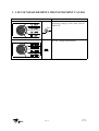
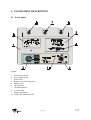
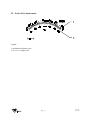
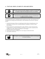
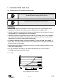
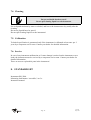
1
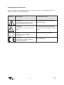
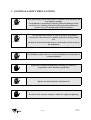
User manual
ISO 5000
Insulationtester
Supplier:
Specifications of the equipment:
Specifications of the user manual:
Nieaf-Smitt
Vrieslantlaan 6
3526 AA Utrecht Holland
P.O. box 7023 3502 KA Utrecht
ISO 5000
Date : 17 April, 2003
Number: 561144046
Ref.: 002
Preface
This manual describes the Insulation ISO 5000 Tester. The information in this manual is
important for proper and safe functioning of the machine. In case you are not familiar with the
operation, the preventive maintenance, etc. of the ISO 5000 Tester, then you need to read this
user manual from the beginning to the end thoroughly.
If you are familiar with these matters, you can use this manual for reference. You can find the
required information rapidly using the table of contents.
In this user manual, the following four marking conventions are used to focus attention on
certain subjects of actions.
TIP:
gives you suggestions and advice to perform certain tasks easier or faster.
ATTENTION:
a remark with additional information; draws your attention to possible problems.
CAUTION:
the machine may be damaged, if you do not carefully execute the procedures.
WARNING FOR DANGER:
you can (seriously) hurt yourself or seriously damage the product, if you do not
carefully execute the procedures.
-
this document is described with the words “manual” or “user manual”;
the test equipment is described with the words “tester”, “instrument” or “test device”;
values or displayed data is placed between inverted commas for example “230 V”;
- Page 2 -
Utrecht
Ref. 002
Warranty
Nieaf-Smitt bv guaranties the tester for a period of 6 months.
The period of warranty will be effective at the day of delivery. The warranty clauses and the
stipulations regarding liability in terms of delivery (FME and HE).
© Copyright 1997
All rights reserved. Nothing from this edition may be multiplied, or made public in any form or
manner, either electronically, mechanically, by photocopying, recording, or in any manner,
without prior written approval from Nieaf-Smitt bv.
Nieaf-Smitt bv reserves the right to change parts at any given moment, without prior or direct
notification to the client. The contents of this user manual may also be changed without prior
warning.
This user manual is compiled with all possible care, but Nieaf-Smitt bv can not accept any
responsibility for possible errors in this user manual or any consequences resulting from that.
- Page 3 -
Utrecht
Ref. 002
Warning pictograms on the tester
There are a number of pictograms on the tester, meant to warn the user of remaining risks that
may be present in spite of the safe design.
Pictogram
Description
Location on the tester
Warning:
General sign for danger. Read the
instructions carefully before use.
At the front side of the tester on the
instruction label.
Warning:
Danger for direct contact with live
parts.
At the front side of the tester on the
instruction label and under the battery
cover.
Mark:
Insulation class II (double
insulation).
At the front side of the tester.
CE-mark:
Declares the conformity with the
European Directives.
The CE-mark is placed on the front
side of the tester.
- Page 4 -
Utrecht
Ref. 002
CONTENTS
1.
GENARAL SAFETY REGULATIONS.............................................................6
2.
INTRODUCTION................................................................................................7
3.
LIST OF MEASUREMENTS THE INSTRUMENT CAN DO.......................8
4.
TECHNICAL SPECIFICATIONS.....................................................................9
5.
INSTRUMENT DESCRIPTION ........................................................................10
5.1. Front panel ...........................................................................................................10
5.2. Scale of the Instrument ........................................................................................11
6.
INSTALLATION; START-UP AND ADJUSTING .........................................12
7.
INSTRUCTION FOR USE .................................................................................13
7.1. Measurement of Insulation Resistance ................................................................13
7.2. Measurement of DC or AC Voltage ....................................................................14
7.3. Replacement of Batteries .....................................................................................15
7.4. Cleaning ...............................................................................................................16
7.5. Calibration............................................................................................................16
7.6. Service..................................................................................................................16
8.
STANDARD SET .................................................................................................16
- Page 5 -
Utrecht
Ref. 002
1. GENERAL SAFETY REGULATIONS
Read, before you perform any action in connection with the tester, this
user manual carefully.
Nieaf-Smitt bv is not liable for injuries, (financial) damage and/or
excessive wear resulting from incorrectly performed maintenance,
incorrect use of or modifications to the instrument.
It is not allowed to remove, to skirt or to tide over (by handy
constructions) the enclosure or safeties of the tester during normal
use.
Method of measurement and range are indicated on the back side of
the instrument.
It’s forbidden to place and/or to use the instrument in a room where is
a risk of explosion.
If the tester is used by a third party, you being the owner are
responsible, unless otherwise specificated.
Repair can only be done by Nieaf-Smitt bv.
Provide a clean and save workplace which has sufficient lightning.
- Page 6 -
Utrecht
Ref. 002
2. INTRODUCTION
The ISO 5000 Meter is a professional instrument intended for the measurement of insulation
resistance from 500kΩ up to 500 GΩ using dc test voltages of 500, 1000, 2500 and 5000V
and also for the measurement of dc and 50Hz ac voltages up to 600V.
The instrument is incorporated into a robust portable plastic casing which ensures its
insensibility to mechanical strains as well as its safe operation. It is battery powered (4 x 1.5V
dc IEC LR20) for autonomous operation. Its logarithmic scale provides an easy and accurate
reading of the measurement results.
- Page 7 -
Utrecht
Ref. 002
3. LIST OF MEASUREMENTS THE INSTRUMENT CAN DO
Rotary switch and START key position
Function
Insulation resistance measurement using
measuring voltage of 500, 1000, 2500 or
5000 Vdc
AC/DC voltage measurement
- Page 8 -
Utrecht
Ref. 002
4. TECHNICAL SPECIFICATIONS
Insulation resistance
Measuring range:
Measuring voltage:
Short circuit measuring
current:
Scale:
Accuracy:
START HOLD system:
Discharging of line:
Max. overvoltage:
500 kΩ ÷ 500 GΩ
500, 1000,2500, 5000 Vdc
approx. 1,3 mA
logarithmic, l=90 mm
± 2 mm
Included
automatic, when START key is not pressed
1,3 x UN
Voltage
Measuring range:
Input resistance
DC voltage:
Input resistance
AC voltage:
Scale:
Accuracy:
0 - 600 Vac/dc
3 MΩ
1,35 MΩ
linear, l=90 mm
± 2 % of full scale
General
Power supply:
LOW BAT indicator:
Dimensions (WxHxL):
Case:
Working temp. range:
Nominal temp. range:
Storage temp. Range:
Max. working humidity:
Max. storage humidity:
Mass:
Battery life time
(open circuit, 5kV, 5s/25s measurement
system):
Overvoltage category:
Protection classification:
Pollution degree:
Batteries 4 x 1,5 Vdc IEC LR20
red LED
345 x 130 x 250 mm
robust, plastic
0 ÷ 40 °C
10 ÷ 30 °C
-10÷60 °C
85% RH (0÷40 °C)
90% RH (-10÷40 °C)
80% RH (40÷60 °C)
4,5 kg
500 h approx.
III 600V
double insulation
2
- Page 9 -
Utrecht
Ref. 002
5. INSTRUMENT DESCRIPTION
5.1. Front panel
Legend:
1
2
3
4
5
6
7
8
9
10
Front panel, plastic
Test voltage switch
START key
Battery cover fastening screw
Battery cover
- Rx terminal
GUARD terminal
+ Rx terminal
Pointer instrument
LOW BAT indication LED
- Page 10 -
Utrecht
Ref. 002
5.2. Scale of the Instrument
1
2
Legend:
1. Insulation resistance scale
2. dc. or ac. voltage scale
- Page 11 -
Utrecht
Ref. 002
6. INSTALLATION; START-UP AND ADJUSTING
The tester can only be used if no damages or defects are noticed and
all original components belonging to the tester are mounted
The transportation and the handling of the tester should be done
carefully to prevent any damage.
This paragraph describes the installation and the starting up procedure of the instrument. The
installation, the starting up and the adjustment of the instrument may be done by competent
persons.
1. Unpack the instrument. Remove the packing materials without causing damages to the
environment. Check the tester on possible damages. If damages are noticed, contact
Nieaf-Smitt bv..
2. Put the instrument in a horizontal position, at the workplace or in the test room. Keep
enough clearance around the instrument to facilitate an easy operation, adjustment and
reading of test results, without any problems or extra danger.
3. Insert the batteries in the instrument.
4. Connect the test object according to the circuit diagrams with the ISO 5000.
5. Carry out the selected test.
Find a place to put the manual such that it is within reach during the
use of the instrument.
- Page 12 -
Utrecht
Ref. 002
7. INSTRUCTION FOR USE
7.1. Measurement of Insulation Resistance
Do not touch the test object or the test cords during the measurement
because hazardous voltage can be present.
Do not connect tested object to a power source.
WARNINGS:
1. Before connecting the instrument to tested object, make sure START button of the
instrument is released; the voltage at test terminals can be as high as 5kV.
2. Should a capacitive tested object be disconnected during the measurement, it remains
charged and has to be discharged before touching it.
3. When performing a long-duration test (START key is locked), check every 5 minutes
the tested object for insulation breakdown. If breakdown is detected, switch off the
instrument to avoid any useless battery discharging.
4. Continuous maximal voltage at the test terminals (V-meter) is 1000V dc or 1000V ac
peak value. As a general rule, disconnect test terminals of the instrument immediately
if tested voltage exceeds 600V.
5. During the measurement of insulation resistance check the condition of batteries (the
red LED should not light).
6. Use the instrument according to this Instruction manual only. Do not connect
GUARD terminal to hazardous voltage.
Test voltage:
Typical diagram of test voltages
- Page 13 -
Utrecht
Ref. 002
The usage of GUARD terminal:
In general the measurements of insulation resistance are carried out without using the
GUARD terminal. If e.g. a coaxial cable is being tested, the test result can be the consequence
of both insulation's conductivity and of insulation's surface conductivity. If one wants to
eliminate the influence of the surface conductivity (which appears either due to humidity in
the atmosphere or due to dirt) the terminal GUARD should be used as shown in figure below:
7.2. Measurement of DC or AC Voltage
WARNINGS:
1. For voltage measurements it is not necessary to insert the batteries or to test the battery
condition.
Max. allowed input voltage is 600 Volts.
2. Continuous maximal voltage at the test terminals (V-meter) is 1000V dc or 1000V ac peak
value. As a general rule, disconnect test terminals of the instrument immediately if tested
voltage exceeds 600V.
3. Before connecting the instrument to tested object, make sure START button of the
instrument is released; the voltage of the terminals can be as high as 5kV.
Connect test leads to the tested voltage as shown in figure below:
- Page 14 -
Utrecht
Ref. 002
The instrument indicates the value of dc voltage or rms ac voltage (50Hz) without depressing
START key.
7.3. Replacement of Batteries
Exchange all four batteries.
Disconnect all cables before removing the battery cover.
Caution, possible live parts under the battery cover
Throw, after using, the empty batteries in the special battery basket.
If the red LED starts to light during the insulation resistance measurement, this indicates that
the batteries are used up and should be replaced. The accuracy of the test results, when the red
LED lights, can not be guaranteed. Red LED starts to light in case battery voltage is lower
than 4,2V approx..
ATTENTION
• If one intends not to use the instrument for a longer time period, it is advisable to remove
the batteries in order from it to avoid possible leak of acid.
• Use the batteries of IEC LR20 type (4 x 1.5V dc).
• Always replace all four batteries.
- Page 15 -
Utrecht
Ref. 002
7.4. Cleaning
Do not use liquids based on petrol!
Do not spill cleaning liquid over the instrument.
Use soft patch moistens by water or alcohol, and leaves the instrument to dry totally after the
cleaning.
Do not use liquids bared or petrol!
Do not spill cleaning liquid over the instrument!
7.5. Calibration
Technical specification is guaranteed only if the instrument is calibrated at least once per 2
years by a competent service-man. Contact your dealer for detailed information.
7.6. Service
In case of any instrument malfunction or if some damage is noticed on the instrument or test
leads, the instrument must be serviced by a competent service-man. Contact your dealer for
detailed information.
There are no user replaceable parts in the instrument!
8. STANDARD SET
Instrument ISO 5000.
Measuring lead banana / crocodile, 2 m: 3x.
Instruction manual.
- Page 16 -
Utrecht
Ref. 002