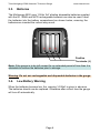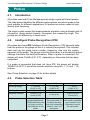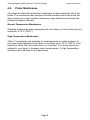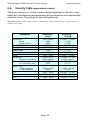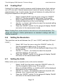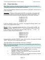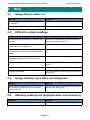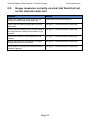
1
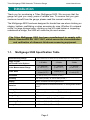
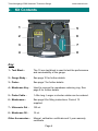
Ultrasonic Thickness Gauge
Tritex Multigauge 5500 Ultrasonic Thickness Gauge
www.tritexndt.com
Multigauge 5500
User Manual
simple . accurate . robust
Page
www.tritexndt.com
Tritex Multigauge 5500 Ultrasonic Thickness Gauge
www.tritexndt.com
Contents
1. Introduction
3
1.1.
3
Multigauge 5500 Specification table
2. Kit Contents
4
3. Getting Started
5
3.1.
3.2.
3.3.
3.4
Quick Start Guide
Assembly
Batteries
Low Battery Warning
4. Probes
4.1.
4.2.
4.3.
4.4.
4.5.
4.6.
7
Introduction
Intelligent Probe Recognition (IPR)
Probe Selection Table
Probe Membranes
Changing the Membrane
Care of Probes
5. Getting to know your Multigauge 5500
5.1.
5.2.
5.3.
5.4.
5.5.
Switching the Gauge On
Switching the Gauge Off
Automatic Shutoff
Belt Attachment Clip
Measurement Hold Feature
6. Navigating the Menus
6.1.
6.2.
6.3.
6.4.
6.5.
6.6.
6.7.
6.8.
6.9.
7
7
7
8
9
9
10
11
11
11
11
11
12
Entering the Menus
Navigation Table
Setting the Calibration
Velocity Table
Coating Plus+
Setting the Resolution
Setting the Units
Probe Selection
Probe Sensitivity
7. Using the Multigauge 5500
7.1.
7.2.
7.3.
5
5
6
6
How Triple Echo Works
Echo Strength Indicator
Precautions when Measuring
Page 1
12
12
13
14
15
15
15
16
17
18
18
19
19
Tritex sales 04 - Issue 2 - January 2008
Tritex Multigauge 5500 Ultrasonic Thickness Gauge
www.tritexndt.com
8. Help
8.1.
8.2.
8.3.
8.4.
8.5.
21
Gauge fails to switch on
Difficult to obtain readings
Gauge displays up to three ascending bars
Standing readings are displayed when not measuring
Gauge measures correctly on steel test block
but not on material under test
9. General Information
9.1.
9.2.
9.3.
9.4.
9.5.
9.6.
21
21
21
21
22
23
Safety
RoHS
WEEE Disposal Instructions
Cleaning
Warranty
Service & Repair
10. Contact Information
23
23
23
24
24
25
26
Page 2
Tritex Multigauge 5500 Ultrasonic Thickness Gauge
www.tritexndt.com
1. Introduction
Thank you for purchasing a Tritex Multigauge 5500. We are sure that the
gauge will give you many years of reliable use. To ensure that you gain
maximum benefit from the gauge, please read this manual carefully.
The Multigauge 5500 has been designed for hands free use when climbing on
staging, ladders, scaffolding or when accessing by rope. Whether it’s onboard
a ship, on large storage tanks, climbing on top of a road tanker or inspecting
underneath a bridge, the 5500 will make the job much easier.
The Tritex Multigauge 5500 has been manufactured to comply with
British Standard BS EN 15317:2007, which covers the characterisation
and verification of ultrasonic thickness measuring equipment.
1.1.
Multigauge 5500 Specification Table
Sound Velocity Range
Single Crystal
Soft Faced Probe Options
From 1000 m/s to 8000 m/s (0.0394 in/µs to 0.3150 in/µs)
2.25 MHz
3.5 MHz
5 MHz
Probe Measurement Range
3 - 250 mm
(0.120” to 10”)
2 - 150 mm
(0.080” to 6”)
1 - 50 mm
(0.040” to 2”)
Probe Sizes
13 mm (0.5”) &
19 mm (0.75”)
13 mm (0.5”)
6 mm (0.25”) &
13 mm (0.5”)
Resolution
0.1 mm (0.005”) or 0.05 mm (0.002”)
Accuracy
± 0.1 mm (0.005”) or ± 0.05 mm (0.002”)
Display
Red 4 character seven segment LED
Batteries
3 x Disposable AA alkaline batteries or rechargeable NiMH /
NiCD
Battery Life
20 Hours continuous use using alkaline batteries
Gauge Dimensions
147 mm x 90 mm x 28 mm (5.75” X 3.5” X 1”)
Gauge Weight
320g (11.3 ounces) including batteries
Environmental
Case rated to IP65. RoHS and WEEE compliant
Operating Temperature
-10°C to +50°C (14°F to 122°F)
Storage Temperature
-10°C to +60°C (14°F to 140°F)
Page 3
Tritex Multigauge 5500 Ultrasonic Thickness Gauge
www.tritexndt.com
2. Kit Contents
1
5
2
6
3
7
4
8
Key:
1 - Test Block -
The 15 mm test block is used to test the performance
and serviceability of the gauge.
2 - Gauge Body -
See page 10 for further details.
3 - Probe -
See page 7 for further details.
4 - Membrane Key -
Used to remove the membrane retaining ring. See
page 9 for further details.
5 - Probe Cable -
1.45m long. Longer or shorter cables can be ordered.
6 - Membranes -
See page 9 for fitting instructions. Pack of 10
supplied.
7 - Ultrasonic Gel -
150 ml.
8 - Membrane Oil -
15 ml.
Other Accessories -
Manual, calibration certificate and 3 year warranty
certificate.
Page 4
Tritex Multigauge 5500 Ultrasonic Thickness Gauge
www.tritexndt.com
3. Getting Started
3.1.
Quick Start Guide
Following is a quick start guide to help you get a feel for the gauge without
reading the entire manual. For a more detailed explanation of each of these
steps, please read the full manual.
1
Unscrew the probe knurled ring and apply a few drops of
membrane oil to the face of the probe. (Pg 9)
2
Screw the knurled ring back onto the probe ensuring no
air has been trapped and the membrane is flat to the probe
face. (Pg 9)
3
Connect the probe, cable and gauge together. (Pg 5)
4
Turn the gauge on using the ‘ON/OFF’ switch. (Pg 11)
5
Apply a small amount of ultrasonic gel to the surface being
measured. (Pg 19)
3.2.
6
Place the probe onto the ultrasonic gel / test piece.
7
A measurement will be displayed.
Assembly
To assemble the gauge for use:
i
ii
Attach the probe to the probe cable by pushing the cable
Lemo plug into the socket on the probe.
Connect the other end to the gauge Lemo socket.
Note: To remove the connectors, simply pull back on the connector collars to
release the plug from the socket. Do not force under any circumstances.
Page 5
Tritex Multigauge 5500 Ultrasonic Thickness Gauge
3.3.
www.tritexndt.com
Batteries
The Multigauge 5500 uses 1.5Vdc ‘AA’ alkaline disposable batteries supplied
with the kit. NiMH and NiCD rechargeable batteries can also be used. Insert
the batteries into the battery compartment as shown below, ensuring the
batteries are inserted the correct way round:
+ + +
Positive
Terminals (+)
Note: If the gauge is to be left unused for an extended period of time then it is
advisable to remove the batteries prior to storage.
Warning: Do not mix rechargeable and disposable batteries in the gauge.
3.4.
Low Battery Warning
When the batteries become low, the warning ‘LO Bat’ is given in advance.
The batteries should now be replaced. Otherwise after a short time the gauge
will turn off automatically.
Page 6
Tritex Multigauge 5500 Ultrasonic Thickness Gauge
www.tritexndt.com
4. Probes
4.1.
Introduction
All probes used with Tritex Multigauges are single crystal soft faced probes.
The table below identifies the different probe options and which probe is the
most suitable for different applications. All probes are colour coded to help
identify their frequency.
The single crystal means that measurements are taken using a straight path of
ultrasound, giving perfect linearity throughout the measuring range. The
probes are not affected by V-beam error.
4.2.
Intelligent Probe Recognition (IPR)
All probes also have IPR (Intelligent Probe Recognition). IPR transmits data
from the probe to the gauge so that it is instantly recognised. This includes
data such as the probe serial number, frequency, size and the unique
signature of the probe. The gauge uses this information to automatically adjust
settings to achieve the best performance. When a probe is connected, the
display will show ‘ProbE=2.25 P13’, depending on the probe that has been
connected.
If a probe is connected that does not have IPR, the gauge will display
‘SELECt=2.25 P13’ and allow manual selection using the ‘+’ (1) and ‘-’ (3)
buttons.
See ‘Probe Selection’ on page 16 for further details.
4.3.
Probe Selection Table
Frequency
Measuring Range
Colour
Diameters Available
Suitable for
2.25 MHz
3 - 250 mm
(0.120” to 10”)
Yellow
3.5 MHz
2 - 150 mm
(0.080” to 6”)
Green
5 MHz
1 - 50 mm
(0.040” to 2”)
Blue
13 mm (0.5”) &
19 mm (0.75”)
13 mm (0.5”)
6 mm (0.25”) &
13 mm (0.5”)
Most thickness
Will measure relatively
gauging applications.
thin metal which is
Works particularly well
corroded. Normally
on heavy corrosion, used only if measuring
especially the 19 mm
down to 2 mm is of
probe.
importance.
Page 7
Ideal for measuring
thin metal in relatively
good condition. Not
advisable to use as
the main probe.
Tritex Multigauge 5500 Ultrasonic Thickness Gauge
4.4.
www.tritexndt.com
Probe Membranes
All probes are fitted with protective membranes to help prolong the life of the
probe. The membranes also provide a flexible interface which acts as an aid
when working on rough surfaces. Membrane wear should be monitored and
checked at regular intervals.
Normal Temperature Membranes
Standard membranes allow measurements to be taken on hot surfaces up to a
maximum of 70°C (158°F).
High Temperature Membranes
Teflon™ membranes are available for measurements on hotter surfaces. In
this case measurements can be taken on surfaces up to 150°C (302°F). Care
should be taken that the probe does not overheat. The probe should be
allowed to cool down in between each measurement. A high temperature
ultrasonic gel is advised for this application.
Page 8
Tritex Multigauge 5500 Ultrasonic Thickness Gauge
4.5.
www.tritexndt.com
Changing the Membrane
Membrane
Oil
www.tritexndt.com
Membrane
Key (5)
Knurled Ring (1)
Membrane (2)
Retaining Ring (3)
Probe (4)
i
ii
iii
iv
v
vi
vii
Membrane
Oil (6)
Lemo
Connector
Unscrew the knurled ring (1) from the probe (4).
Using the membrane key (5), remove the retaining ring (3)
from inside the knurled ring (1).
Push the old membrane (2) out from the front.
Fit a new membrane (2) from the back and push it down until
it locates in the groove on the inside front edge.
Refit the retaining ring (3) and secure it in place using the
membrane key (5).
Place a few drops of membrane oil (6) onto the face of
the probe (4). Do not use too much.
Screw the knurled ring (1) back onto the probe (4) whilst
applying pressure on the membrane (2) with the thumb to
expel any air from behind the membrane.
Note: Do not apply too much membrane oil underneath the membrane. Once
fitted, the membrane should be flat with no air bubbles trapped behind.
Warning: Never use a probe without a membrane fitted
4.6.
Care of Probes
All probes should be treated with respect. When taking measurements, they
should not be scraped or dragged along the surface. Although the membranes
will protect the probe against everyday wear and tear, they will not protect
against rough treatment and misuse.
Warning: Never try to repair a probe or try to remove scratches from the face
of the probe. This may result in further damage. Always return it to Tritex NDT
for investigation and possible repair.
Page 9
Tritex Multigauge 5500 Ultrasonic Thickness Gauge
www.tritexndt.com
5. Getting to know your Multigauge 5500
Front
Back
Belt
Attachment
Button (4)
Up Selection (1)
ON/OFF &
Menu Button (2)
Down
Selection (3)
Battery
Compartment (5)
Probe Cable
Connector (7)
LED Display (6)
Belt Attachment Clip (8)
Page 10
Tritex Multigauge 5500 Ultrasonic Thickness Gauge
5.1.
www.tritexndt.com
Switching the Gauge On
i
ii
iii
To switch the gauge on press the ‘ON/OFF’ switch (2)
The display will show a greeting message ‘HELLO’ followed
by the current velocity of sound setting.
One or two flashing bars will indicate that the gauge is ready
to measure.
Note 1: If no probe is connected when the gauge is turned on, the display will
show ‘no ProbE’. See page 17 for further details.
Note 2: If a probe other than a Tritex probe is attached before switching on
then the gauge will display ‘SELECt=2.25 P13’. See manual selection on
page 16 for further details.
5.2.
Switching the Gauge Off
i
ii
5.3.
To switch the gauge off, press and release the ‘ON/OFF’
switch (2).
After a few seconds the gauge will display ‘byE byE’ and turn
off.
Automatic Shutoff
The gauge will automatically shut off after 10 minutes of inactivity to save
battery power.
5.4.
Belt Attachment Clip
i
ii
iii
5.5.
Secure the Belt Attachment Clip (8) onto a waist belt.
Locate the Belt Attachment Button (4) on the back of the
gauge into the slot on the Belt Attachment Clip (8) and slide
down until a positive lock is heard and felt.
To release the gauge from the Belt Attachment Clip (8),
squeeze both buttons on either side of the clip and slide the
gauge upwards.
Measurement Hold Feature
To hold a measurement, press either the ‘+’ (1) or ‘-’ (3) buttons whilst a
measurement is displayed.
Page 11
Tritex Multigauge 5500 Ultrasonic Thickness Gauge
www.tritexndt.com
6. Navigating the Menus
6.1.
Entering the Menus
i
ii
iii
iv
6.2.
Press and hold the ‘ON/OFF’ switch (2) for a few seconds.
The display will show the first menu item ‘CAL’.
To navigate the menus use the ‘ON/OFF’ button (2).
After scrolling through once, the gauge will return to
measurement mode.
Navigation Table
Menu
Calibration
Velocity Setting
On
Coating
Plus+
Off
Low (Lo)
Resolution
High (HI)
Metric (European)
Units
Imperial (Inches)
Probe Select
Probe Setting
Sensitivity
Sensitivity Setting
Back to
measurement
mode
Page 12
Only shown in the menu
when no probe or a
compatible probe
without IPR has been
connected.
Tritex Multigauge 5500 Ultrasonic Thickness Gauge
6.3.
www.tritexndt.com
Setting the Calibration
The gauge should be calibrated to the type of material that is being measured.
This is because all materials have different velocity of sound properties.
There are two methods of changing the calibration. Either adjust the velocity of
sound setting according the metal being measured, or adjust the the gauge to
a known thickness of metal.
Gauges are supplied with the calibration set to mild steel at approximately
5900 m/s (0.2323 in/µs). This may vary according to the properties of the
supplied 15 mm test block material.
Note: The calibration does not need to be reset each time the gauge is used.
The last setting will be remembered.
Calibrating the Velocity of Sound
i
ii
iii
iv
Select ‘CAL’ from the menu using the ‘ON’OFF’ button (2).
Use the navigation table on pg 12 as a guide.
‘CAL’ and the current velocity setting will be displayed
alternately.
Use the ‘+’ (1) and ‘-’ (3) buttons to adjust the velocity of
sound to the the required new velocity.
Press the ‘ON/OFF’ button (2), the gauge will display ‘rEADY’
and return to the measurement mode.
Calibrating to a Known Thickness
i
ii
iii
iv
v
vi
Select ‘CAL’ from the menu using the ‘ON/OFF’ button (2).
Use the navigation table on pg 12 as a guide.
‘CAL’ and the current velocity setting will be displayed
alternately.
Place the probe on a piece of material of a known thickness
such as the test block supplied with the kit.
‘CAL’ and the measurement will be displayed alternately.
Adjust the measurement displayed to the known thickness
using the ‘+’ (1) and ‘-’ (3) buttons.
Press the ‘ON/OFF’ button (2), the gauge will display ‘rEADY’
and return to the measurement mode.
Page 13
Tritex Multigauge 5500 Ultrasonic Thickness Gauge
6.4.
www.tritexndt.com
Velocity Table (approximate values)
The given values are in certain cases strongly dependent on the alloy, heat
treatment, manufacturing and processing and are therefore only approximate
standard values. They are given here as a guide only.
Reference: Mathies, Klaus (1998), Thickness Measurement with Ultrasound, Berlin: German Society of
Nondestructive Testing.
Material
Aluminium
Rolled
Duraluminium
Bronze (5%P)
Copper
Glass, Plate
Inconel, Forged
Lead
Steel, Mild
Supplied Test Block
Steel, Stainless
10 Cr Ni 18 8, ann
Steel, Tool
C105 Annealed
C105 Hardened
Tin
Titanium
Zinc
Velocity m/s
Velocity in/µs
6200 -6360
6420
6320
3531
3666 - 4760
5766
7820
2050 - 2400
5890 - 5960
5900 approx.
5530 - 5790
5530
0.2441 - 0.2504
0.2528
0.2488
0.1390
0.1443 - 0.1874
0.2270
0.3079
0.0807 - 0.0945
0.2319 - 0.2346
0.2323 approx.
0.2177 - 0.2280
0.2177
5490 - 5960
5854
3210 - 3320
5823 - 6260
3890 - 4210
0.2339 - 0.2346
0.2305
0.1264 - 0.1307
0.2293 - 0.2465
0.1531 - 0.1657
Page 14
Tritex Multigauge 5500 Ultrasonic Thickness Gauge
6.5.
www.tritexndt.com
Coating Plus+
Coating Plus+ mode is used to measure metal thickness when thick coatings
up to 20 mm exist. Normal measurement mode will ignore coatings up to
approximately 6 mm. In both modes, the actual thickness of coating that can
be ignored depends on the type of coating.
i
ii
iii
iv
Select ‘CoatinG-PLUS’ from the menu using the ‘ON/OFF’
button (2). Use the navigation table on pg 12 as a guide.
Either ‘CoatinG-PLUS=On’ or ‘CoatinG-PLUS=OFF’ will be
displayed depending on the current setting.
Use the ‘+’ (1) and ‘-’ (3) buttons to select the required setting
between ‘ON’ and ‘OFF’.
Press the ‘ON/OFF’ switch (2), the gauge will display ‘StorEd’
and return to the measurement mode.
Note: Coating Plus+ mode should not be left on for all measurements. The
gauge will achieve a better performance on standard coatings with this
function turned off.
6.6.
Setting the Resolution
The resolution can be set between low (0.1 mm / 0.005”) and high (0.05 mm /
0.002”).
i
ii
iii
iv
6.7.
Select ‘rES’ from the menu using the ‘ON/OFF’ button (2).
Use the navigation table on pg 12 as a guide.
Either ‘rES=LO’ or ‘rES=HI’ will be displayed depending on the
current setting.
Use the ‘+’ (1) and ‘-’ (3) buttons to select the required
resolution between ‘HI’ and ‘LO’.
Press the ‘ON/OFF’ switch (2), the gauge will display ‘StorEd’
and return to the measurement mode.
Setting the Units
Either metric (mm) or imperial (inch) units can be selected.
i
ii
iii
iv
Select ‘UnitS’ from the menu using the ‘ON/OFF’ button (2).
Use the navigation table on pg 12 as a guide.
Either ‘UnitS=EUrOPEAn’ or ‘UnitS=InchES’ will be displayed
depending on the current setting.
Use the ‘+’ (1) and ‘-’ (3) buttons to select the required units
between ‘Euro’ (metric) and ‘Inch’ (imperial).
Press the ‘ON/OFF’ switch (2), the gauge will display ‘StorEd’
and return to the measurement mode.
Page 15
Tritex Multigauge 5500 Ultrasonic Thickness Gauge
6.8.
www.tritexndt.com
Probe Selection
Note: Probe selection will only be shown in the menu when no probe or a
compatible probe without IPR has been connected.
There are three different modes for probe selection: automatic, manual and no
probe connected.
Automatic - When a Tritex probe with IPR is connected, the gauge will
automatically identify the probe type and set the gauge accordingly. The
following will scroll across the display depending on the probe connected:
ProbE=2.25 P13
ProbE=2.25 P19
ProbE=3.5 P13
ProbE=5.0 P13
ProbE=5.0 P6
Press the ‘ON/OFF’ button (2) to confirm, the gauge will display ‘rEADY’ and
return to the measurement mode.
Manual - When a compatible probe other than a Tritex probe is fitted, the
gauge will display ‘SELECt=2.25 P13’. This is a prompt to select the correct
probe setting for the probe that has been fitted. Use the ‘+’ (1) and ‘-’ (3)
buttons to select from the following list:
SELECt=2.25 P13
SELECt=2.25 P19
SELECt=3.5 P13
SELECt=5.0 P13
SELECt=5.0 P6
Once selected, press the ‘ON/OFF’ button (2) to confirm, the gauge will display
‘rEADY’ and return to the measurement mode.
The probe setting can be changed in the menu as follows:
Note: This feature only shows in the menu if a compatible probe other than a
Tritex probe with IPR is fitted.
i
ii
iii
Select ‘SELECt=2.25 P13’ (depending on the current setting)
from the menu using the ‘ON/OFF’ button (2). Use the
navigation table on pg 12 as a guide.
Use the ‘+’ (1) and ‘-’ (3) buttons to select the required probe
setting from the list above.
Press the ‘ON/OFF’ switch (2), the gauge will display ‘StorEd’
and return to the measurement mode.
Page 16
Tritex Multigauge 5500 Ultrasonic Thickness Gauge
www.tritexndt.com
No Probe - If no probe is connected when the gauge is turned on the display
will show ‘no ProbE’. Either connect a suitable probe or simply press the
‘ON/OFF’ switch (2) to enter measurement mode. This will allow navigation of
the menus without a probe fitted.
In this case, ‘no ProbE’ will appear in the menu.
6.9.
Probe Sensitivity
Note: This feature only appears in the menu if a compatible probe other than a
Tritex probe with IPR is fitted.
When compatible probes are connected, it is essential to first manually select
the appropriate probe as per 6.8. above, and then to adjust the sensitivity to
obtain the best performance for the probe. Sensitivity can be selected between
1 and 15. The sensitivity setting is specific to each probe setting. Therefore, if
a different probe is selected then the sensitivity may need to be re-adjusted.
Warning: Adjusting the sensitivity to an incorrect setting could affect the
performance of the gauge.
i
ii
iii
Select ‘Sens= 8’ (depending on the current setting) from the
menu using the ‘ON/OFF’ button (2). Use the navigation table
on pg 12 as a guide.
Use the ‘+’ (1) and ‘-’ (3) buttons to select the required probe
sensitivity.
Press the ‘ON/OFF’ switch (2), the gauge will display ‘StorEd’
and return to the measurement mode.
Page 17
Tritex Multigauge 5500 Ultrasonic Thickness Gauge
www.tritexndt.com
7. Using the Multigauge 5500
7.1.
How Triple Echo Works
All Ultrasonic Thickness Gauges should be calibrated to the velocity of sound
of the material being measured. Coatings have a different velocity of sound
than metal and it is important they are not included in the measurement. Triple
echo ensures all coatings are completely eliminated from the measurement.
How it works:
A transmitted ultrasound pulse travels though both the coating and the metal
and reflects from the back wall. The returned echo then reverberates within the
metal, with only a small portion of the echo travelling back through the coating
each time. The timing between the small echoes gives us the timing of the
echoes within the metal, which relate to the metal thickness. The returned
echoes need not be consecutive as the gauge will interpret them automatically
and calculate the thickness. A minimum of three echoes is checked each time.
This is referred to as the Automatic Measurement Verification System
(AMVS).
Probe
Coating
Page 18
Timing 3
Timing 2
Timing 1
Metal
Tritex Multigauge 5500 Ultrasonic Thickness Gauge
7.2.
www.tritexndt.com
Echo Strength Indicator
The gauge will display a series of flashing bars to indicate the strength of the
returning echoes. The stronger the returning echoes are, the more bars will be
displayed.
7.3.
Precautions When Measuring
Check that the material has parallel front and back walls.
If the front and back walls are not parallel, the ultrasound
hitting the back wall will be deflected away from the face of the
probe. The probe will therefore not receive any echoes back.
The surface being measured should be free from dirt or
debris. It may be necessary to clean or brush the surface
prior to taking measurements.
Ensure plenty of ultrasonic gel is used between the probe
and the material to eliminate any air pockets. Air is the
enemy of ultrasound and it is essential that couplant exists to
form a path for the ultrasonic signal.
A membrane should be correctly fitted to the probe.
Place the probe firmly on the surface being measured to
make good contact.
Do not remove protective coatings. The gauge is designed
to ignore these.
Ensure the coating is solidly adhered to the surface.
Triple echo will ignore coatings as long as they are solidly
adhered to the surface. If the coating has become loose or
delaminated then air pockets will exist.
Remove debris from the probe face between
measurements.
Sometimes it is necessary to rock the probe slightly and
gently in order to obtain measurements. This often helps
the probe to receive echoes from the back wall.
Page 19
Tritex Multigauge 5500 Ultrasonic Thickness Gauge
www.tritexndt.com
The correct couplant should be used. Although we
recommend couplant specifically designed for taking
measurements, other liquids can be used such as liquid soap,
wallpaper paste, water and some hand cleansers. Grease is
not a good alternative.
Ensure the coating is not layered or does not contain
foreign objects in its construction. Layered coatings cause
reflections at the layer interface. This seriously weakens the
strength of the ultrasound and may prevent it from travelling
all the way through. The same applies to foreign objects which
can deflect the ultrasound path or prevent the ultrasound from
passing.
Some types of casting may cause problems for ultrasonic
gauges. Castings can contain foreign elements within their
construction and they also have varying velocity of sound
properties throughout their structure. This may result in
inaccurate measurements due to the inherent inconsistencies
in the material.
Page 20
Tritex Multigauge 5500 Ultrasonic Thickness Gauge
www.tritexndt.com
8. Help
8.1.
Gauge fails to switch on
Advice
Action
Check the batteries are present and
serviceable.
Replace with new batteries (see pg 6).
The ‘ON/OFF’ key may be defective.
Return the gauge to Tritex NDT (see pg 26).
8.2.
Difficult to obtain readings
Advice
Action
Check the gauge against the 15 mm test block
supplied.
If this works, the problem is with the material
being measured (see pg 19).
Check the correct probe for the material being
measured has been selected.
Select the correct probe (see pg 7).
Check the probe membrane is properly fitted
with membrane oil applied and no trapped air
present.
Refit or replace the membrane (see pg 9).
Check the probe, lead and gauge are all
connected together correctly and securely.
Re-connect as necessary (see pg 5).
Check the serviceability of the probe and lead.
Contact Tritex NDT for replacement items (see
pg 26).
Check the serviceability of the gauge.
Return the gauge to Tritex NDT (see pg 26).
Couplant not suitable.
Use only suitable couplant supplied with the kit
(see pg 20).
8.3.
Gauge displays up to three ascending bars
Advice
Action
Not all echoes received are equal. The gauge
has Automatic Measurement Verification
System (AMVS).
Move or rock the probe slightly until all echoes
are received (see pg 19).
8.4.
Standing readings are displayed when not measuring
Advice
Action
Excessive membrane oil under membrane.
Refit or replace the membrane (see pg 9).
Page 21
Tritex Multigauge 5500 Ultrasonic Thickness Gauge
8.5.
www.tritexndt.com
Gauge measures correctly on steel test block but not
on the material under test
Advice
Action
Check the material is not too thin for the
frequency of the probe being measured.
Select the correct probe (see pg 7).
Check that the material has parallel front and
back walls.
See pg 19 - Precautions When Measuring.
Ensure plenty of ultrasonic gel is used between See pg 19 - Precautions When Measuring.
the probe and the material to eliminate any air
pockets.
Ensure the coating is solidly adhered to the
surface.
See pg 19 - Precautions When Measuring.
Ensure the coating is not layered or contains
foreign objects in its construction.
See pg 20 - Precautions When Measuring.
Some types of casting may cause problems for
ultrasonic gauges.
See pg 20 - Precautions When Measuring.
Page 22
Tritex Multigauge 5500 Ultrasonic Thickness Gauge
www.tritexndt.com
9. General Information
9.1.
Safety
Only use either alkaline, NiMH or NiCD ‘AA’ batteries. Do not mix different
types of battery in the same gauge.
Do not submerge the gauge in water.
Do not open the gauge body other than to change the batteries. Always return
the gauge for repair.
Never dispose of batteries in a fire. There is a serious risk of explosion and/or
the release of highly toxic chemicals.
Do not expose to direct sunlight for extended periods of time.
9.2.
RoHS
New legislation to help safeguard the environment has been introduced to
ensure companies act responsibly. Tritex products are fully RoHS compliant
which means that we do not use hazardous substances and materials at any
stage of manufacture. Lead cadmium, mercury and other such materials used
in electronic equipment are not present in Tritex products.
RoHS compliance is already law in the United Kingdom and European Union
and will soon be adopted in other countries seeking to protect the planet for
future generations.
At Tritex we are aware of our corporate social responsibility towards all our
stakeholders. We take pride in our work and our environment.
9.3.
WEEE Disposal Instructions
Do not dispose of this device with unsorted waste. Improper disposal may be
harmful to the environment. Please refer to your local waste authority for
information on return and collection schemes in your area. Otherwise, return
the product to Tritex NDT for safe disposal.
Page 23
Tritex Multigauge 5500 Ultrasonic Thickness Gauge
9.4.
www.tritexndt.com
Cleaning
Clean the gauge using a mild detergent, a damp (not wet) cloth, or an antistatic wipe. Never use abrasives, solvents or other cleaning products as this
will damage the instrument. Do not soak the gauge with water or other liquids.
9.5.
Warranty
Tritex products are guaranteed against defects in material and/or workmanship
for a period of 3 years from date of delivery.
Any equipment that may be defective should be returned carriage paid direct
to Tritex or to their approved local distributor who will at their discretion repair
or replace equipment that proves to be defective during the warranty period.
This warranty includes parts, labour and return at no charge.
Repairs due to abuse of the equipment, accident, fair wear and tear and use of
non approved third party hardware is not covered by this warranty. Probe
warranty is limited to 1 year and batteries (dry cell or rechargeable) or other
consumable items are not covered by this warranty.
No other warranty is expressed or implied, including but not limited to, the
implied warranties of merchantability and fitness for a particular purpose.
The customer should not attempt any repair as this will void the warranty.
Tritex shall not be liable for collateral or consequential damage of any kind
from either the use or the interpretation of the results from the equipment.
Page 24
Tritex Multigauge 5500 Ultrasonic Thickness Gauge
9.6.
www.tritexndt.com
Service & Repair
A full manufacturer’s factory repair service is available from Tritex NDT.
Priority is given to customer repairs so the gauge can be returned ready for
action in the shortest possible time. The complete kit should be returned to
Tritex direct or through your local agent.
Before you return your gauge
Check through the troubleshooting guide on page 21. If this does not solve the
problem we can sometimes give advice over the phone.
When returning the gauge
If after troubleshooting, the gauge is still faulty, you will need to return your
gauge for repair. Please package the complete kit in a suitable protective
container and return to us at the address on page 26.
Please include your contact details including name, address, e-mail and
phone number, along with a brief description of the problem.
Page 25
Tritex Multigauge 5500 Ultrasonic Thickness Gauge
www.tritexndt.com
10. Contact Information
Telephone:
+44 (0) 1305 257160
Facsimile:
+44 (0) 1305 259573
E-mail:
[email protected]
Website:
www.tritexndt.com
Address:
Unit 10, Mellstock Business Park
Higher Bockhampton
Dorchester
Dorset
DT2 8QJ
United Kingdom
Page 26