1
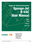
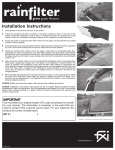
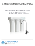
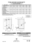
Sponge-Jet® Sponge Blasting System
Sponge-Jet
B-VAC
User Manual
™
Model:
B-VAC Pro 3
Sponge-Jet, Inc. (USA)
235 Heritage Ave., Ste 2
Portsmouth, NH 03801
1-603-610-7950
www.spongejet.com
©2008 Sponge-Jet, Inc. All rights reserved.
Table of Contents
Section
Page
1.0
Introduction
1
2.0
Safety Checklist
4
3.0
Requirements
6
4.0
Operation
9
5.0
Maintenance
20
6.0
Troubleshooting
26
7.0
Drawings
36
Notes
42
1.0 Introduction
Basic
Components
________________________________________
1
1.
2.
3.
4.
5.
6.
7.
8.
9.
10.
11.
2
4
3
Feed Unit Cyclone Storage Silo
400-HP Pressure Vessel
Supply Line Connection
Control Panel
Recovery/Recycler Storage Silo
Vacuum Hose Connector
Lifting Eye
50-P Sponge-Jet Recycler
Vacuum
Twinline Quick Connect Fittings
Waste Drums
6
7
5
9
8
10
11
11
Sponge-Jet B-VAC User Manual – 2/8/2008
-2-
1
Sub-Components
________________________________________
2
3
1.
2.
3.
4.
5.
6.
7.
8.
9.
10.
11.
12.
13.
14.
15.
16.
17.
18.
19.
20.
21.
22.
5
6
4
7
8
9
Blast Pressure Regulator Handle
Emergency Stop Button
Line Pressure Gauge
Media Feed Pressure Regulator Handle
Blast Pressure Gauge
Media Feed Pressure Gauge
Actuation Rate Indicator Eye
Exhaust Muffler
Exhaust Valve
Main Air Ball Valve
Primary Vacuum Air Ball Valve
Primary Recycler Air Ball Valve
Secondary Water Separator
On/Off Control Valve
Blast Pressure Regulator
Control Panel Moisture Separator
Choke Valve
Auger Tunnel End Cap
Air Motor Moisture Separator
Air Motor Lubricator
Clean Out Trap
Blast Hose Connection
10
14
11
13
12
15
16
18
19
17
20
22
21
Sponge-Jet B-VAC User Manual – 2/8/2008
-3-
Sub-Components (continued)
1.
2.
3.
4.
5.
6.
7.
8.
9.
10.
11.
12.
13.
14.
15.
1
4
5
2
3
6
6
Vacuum Ejector
Vacuum Filter Silo
Vacuum Dust Bin
Handhole Cover
Crab Assembly
Pinch Valve and Cover
Filter Cleaning Lever
Media Actuator
Pop-up
Actuator Tree and Chain
Twinline
Blast Hose
Nozzle Holder
Nozzle
Deadman Handle
9
8
10
7
12
13
14
11
12
13
15
Sponge-Jet B-VAC User Manual – 2/8/2008
-4-
Recycler Sub-Components
1.
2.
3.
4.
5.
6.
7.
8.
9.
10.
11.
12.
13.
14.
15.
16.
17.
18.
1
6
2
5
3
7
4
10
8
13
12
9
Dome Lid & Upper Main Rim
Lower Main Rim
Vibratory Section
Safety Skirt
Pan Clamp
Pan Clamp Hook
Pressure Gauge
Secondary Recycler Air Ball Valve
Lubricator
Regulator
Air Filter
Bracket
Supply Line Connection
Reusable Media Downspout
Fine Particle Downspout
Large Particle Downspout
Muffler
Motor
11
16
14
15
18
17
Sponge-Jet B-VAC User Manual – 2/8/2008
-5-
2.0 Safety Checklist
o
The Sponge-Jet Inc. Feed Unit is a pressurized system. Only trained
operators should adjust, maintain and repair this equipment.
o
Inbound pressure should never exceed 8.6bar (125psi).
o
To prevent electrostatic buildup and possible electric discharge, the unit
and work piece must be properly grounded / bonded.
o
Operators and people in proximity to blasting should always wear eye
and hearing protection with the appropriate respiratory equipment and
clothing, which may depend on the type of coating or contaminant being
removed.
o
Never point the Blast Nozzle towards yourself or others.
o
The use of non-Sponge-Jet Deadman handles may cause unintentional
start-up and can result in personal injury.
Before Feed Unit Pressurization and Operation:
o
Verify the Feed Unit is secure and stable.
o
All pneumatic lines should be inspected for holes, wear and proper fit.
o
The Handhole Cover must be in place and secure prior to and during
operation.
o
Safety pins and restraints should be fitted at all Air Supply Hose and
Blast Hose couplings to prevent accidental disconnection.
o
Do not operate without the Auger Chain Guard, Recycler Safety Skirt,
and Pinch Valve Guard in place.
Before all activities (other than normal operation), ensure the entire system
is depressurized.
Sponge-Jet B-VAC User Manual – 2/8/2008
-6-
3.0 Requirements
3.1
Air Supply / Compressor
______________________________________________________________
Clean, dry compressed air must be supplied in adequate volume and
pressure to accommodate the nozzle size at the desired pressure.
Inbound pressure is typically 8.6bar (125psi), minimum 6bar (85psi)
Note: High humidity environments require additional moisture separators.
(Metric) m3/min Requirements
Nozzle Size
No. 6
9.5mm
3/8 in
No. 7
11mm
7/16 in
No. 8
12.5mm
1/2 in
No. 10
15mm
5/8 in
No. 12
18mm
3/4 in
Sponge-Jet B-VAC User Manual – 2/8/2008
4.1bar
4.8bar
5.5bar
6.2bar
6.9bar
8.3bar
Nozzle
3.6
4.0
4.6
4.9
5.5
6.2
B-VAC
8.1
8.1
8.1
8.1
8.1
8.1
Reserve
2.3
2.4
2.5
2.6
2.7
2.9
Total
14.0
14.5
15.1
15.6
16.3
17.1
Nozzle
4.8
5.5
6.1
6.8
7.2
8.5
B-VAC
8.1
8.1
8.1
8.1
8.1
8.1
Reserve
2.6
2.7
2.8
3.0
3.1
3.3
Total
15.5
16.3
17.0
17.8
18.3
19.9
Nozzle
6.3
7.1
7.9
8.7
9.6
11.1
B-VAC
8.1
8.1
8.1
8.1
8.1
8.1
Reserve
2.9
3.0
3.2
3.4
3.5
3.8
Total
17.3
18.2
19.2
20.2
21.2
23.0
Nozzle
10.1
11.4
12.8
14.3
15.5
17.3
B-VAC
8.1
8.1
8.1
8.1
8.1
8.1
Reserve
3.6
3.9
4.2
4.5
4.7
5.1
Total
21.8
23.4
25.0
26.8
28.3
30.4
Nozzle
14.2
16.3
18.4
19.8
22.6
28.6
B-VAC
8.1
8.1
8.1
8.1
8.1
8.1
Reserve
4.4
4.9
5.3
5.6
6.1
7.3
Total
26.7
29.2
31.8
33.5
36.8
44.0
-7-
(Imperial) CFM Requirements
Nozzle Size
No. 6
9.5mm
3/8in
No. 7
11mm
7/16in
No. 8
12.5mm
1/2in
No. 10
15mm
5/8in
No. 12
18mm
3/4in
Nozzle
60psi
4.1bar
126
70psi
4.8bar
143
80psi
5.5bar
161
90psi
6.2bar
173
100psi
6.9bar
196
120psi
8.3bar
220
B-VAC
285
285
285
285
285
285
Reserve
82
86
89
92
96
101
Total
Nozzle
493
170
514
194
535
217
550
240
577
254
606
300
B-VAC
285
285
285
285
285
285
Reserve
91
96
100
105
108
117
Total
546
575
602
678
713
702
Nozzle
224
252
280
309
338
392
B-VAC
285
285
285
285
285
285
Reserve
102
107
113
119
125
135
Total
611
644
678
713
748
812
Nozzle
356
404
452
504
548
611
B-VAC
285
285
285
285
285
40
Reserve
128
138
147
158
167
179
Total
769
827
884
947
1,000
Nozzle
500
575
650
700
800
1,010
B-VAC
285
285
285
285
285
285
Reserve
157
172
187
197
197
259
Total
942
1,032
1,122
1,182
1,302
1,554
1,075
3.2
Air Supply Requirements
______________________________________________________________
Sponge-Jet Feed Units have a 50mm (2in) standard pipe typically fitted with
a 50mm (2in) universal 4 lug coupling. The air supply hose should be fitted
with a mating connector or replace both connectors as desired.
Sponge-Jet B-VAC User Manual – 2/8/2008
-8-
For supply hose up to 50m (150ft) use a Minimum Air Line Internal
Diameter (I.D.) as listed below. For lengths 50 to 90m (150 to 300ft) use a
minimum of one diameter size greater than listed below. Larger hoses
decrease pressure loss.
NOTE: Occasionally a compressor is equipped with undersized outlets. The
compressor air outlet should be no smaller than the recommended Supply
diameters below.
Nozzle Number/Orifice
Minimum Air Line I.D.
#6 - 9.5mm (3/8in)
50mm (2in)
#7 - 11mm (7/16in)
50mm (2in)
#8 - 12.5mm (1/2in)
64mm (2 ½ in)
#10 - 16mm (5/8in)
76mm (3in)
#12 - 19mm (3/4in)
76mm (3in)
3.3
Hoses
______________________________________________________________
Blast Hose
Sponge Media abrasive has been successfully blasted through 90m (300ft)
of Blast Hose. However, when choosing between long Air Supply Line and
long Blast Hoses, keep the Blast Hoses as short as practical. Below are
recommended maximum lengths of blast hoses:
•
Up to 15m (50ft) use 32mm (1.25in) I.D. Whipline connected to the
machine or to a blast hose extension.
•
Extensions up to 30m (100ft) must have a minimum 32mm (1.25in) I.D.
•
Extensions over 30m (100ft) shall use a minimum 38mm (1.5in) I.D.
Blast Hose Extension. Larger hoses decrease pressure loss.
Vacuum Hose
B-VAC’s have successfully recovered Sponge Media at distances in excess
of 100m (330ft). When operating at these distances, optimum performance
is achieved by having the largest diameter vacuum hose closest to the
B-VAC and smaller diameter hose near the pick up location. Long runs of
small hose may result in reduced pick up pressures and high wear in the
hose. Optimum hose configuration starting at the B-VAC is:
• 20 meters (65ft) of 88mm (3.5in) diameter hose connected to
40 meters (130ft) of 76mm (3in) hose connected to
40 meters (130ft) of 63mm (2.5in) hose.
NOTE: Vacuum hoses operate best when running horizontally and or
vertically – gradual slopes (like stairs) should be avoided.
Sponge-Jet B-VAC User Manual – 2/8/2008
-9-
3.4
Ambient Temperature
______________________________________________________________
32º F
0º C
Ambient temperature should be above 0° Celsius (32° Fahrenheit).
Otherwise:
a) Use winter grade pneumatic tool oil in lubricator.
b) Minimize moisture in supply air.
c) Ice build-up in the controls or vessel may require thawing prior to
restarting machine. Bearing grease will thicken in cold environments
requiring use of low temperature grease. Warming the unit prior to operation
may be required. Minimize down time that might result in freezing.
3.5 Containment
Containment is an integral part of the Sponge-Jet process, as Sponge-Jet
Sponge Media is recyclable. To take advantage of this property, containment
must be used to capture and recycle Sponge Media.
Sponge-Jet is easily containable with light plastic sheeting or mesh. Projects
involving hazardous materials, high wind load or other conditions may
require more complex containment and negative air dust collection.
Pre-cleaning of the area will minimize both dust and debris which can also
cause equipment malfunctions.
Always follow local, state and federal guidelines concerning proper
containment, containment ventilation and monitoring procedures.
Sponge-Jet B-VAC User Manual – 2/8/2008
- 10 -
4.0 Operation
Before Pressurization and Operation:
o
All pneumatic lines should be inspected for holes, wear and proper fit.
o
The Handhole Cover must be in place and secure prior to and during
operation.
o
Safety pins and restraints should be fitted at all Air Supply Hose and
Blast Hose couplings to prevent accidental disconnection.
o
Do not operate without the Auger Chain Guard, Recycler Safety Skirt,
and Pinch Valve Guard in place.
o
Before all activities (other than normal operation), ensure the entire
system is depressurized.
Attach Handhole Cover with gasket in place.
____________________________________________________________
Connect Vacuum Hose from the Large Particle Downspout and the Fine
Particle Downspout to each Waste Drum. Check contents of Waste Drums,
remove stored items. Replace or empty drums when 2/3’s full.
____________________________________________________________
Connect outbound Vacuum Hose to Recycler Cyclone Storage Silo
Sponge-Jet B-VAC User Manual – 2/8/2008
- 11 -
Check Pan Clamps for
tightness. They should
not exceed 14kg
(30lbs.) each at the
end of the lever handle.
Adjust by turning the
Pan Clamp Hook.
____________________________________________________________
Insert Whipline through Pinch Valve; connect Blast Hose and secure with
safety pins.
____________________________________________________________
Connect Return and Supply Twinline Quick Connect Fittings.
____________________________________________________________
Ensure the Emergency Stop Button is pushed in (off).
Sponge-Jet B-VAC User Manual – 2/8/2008
- 12 -
Inspect and
clean Exhaust
Muffler.
____________________________________________________________
Ensure adequate tool oil is
visible in the Recycler
Lubricator as well as the
Auger Air Motor Lubricator
(bottom of pressure vessel).
___________________________________________________________
Check Main Air Ball Valve, Primary Vacuum Air Ball Valve and Primary
Recycler Air Ball Valve are closed.
____________________________________________________________
Check Secondary Vacuum Air Ball Valve, Secondary Recycler Air Ball
Valve, and Choke Valve are open.
Sponge-Jet B-VAC User Manual – 2/8/2008
- 13 -
____________________________________________________________
Connect the Supply Line and secure with safety pins and restraints.
____________________________________________________________
Charge Supply Line. Open Main Air Ball Valve
______________________________________________________________
Open Primary Vacuum Air
Ball Valve and Primary
Recycler Air Ball Valve
______________________________________________________________
Attach vacuum hose to Recycler By-Pass Inlet.
______________________________________________________________
Sponge-Jet B-VAC User Manual – 2/8/2008
- 14 -
Load by vacuuming new or recycled Sponge Media as required, remove
hose from By-Pass Valve and secure Inlet.
NOTE: A typical full charge fills the 400 HP Pressure Vessel and the Feed
Unit Cyclone Storage Silo to 2/3 full (the top of the Silo Actuator,
approximately 15 bags of media total).
During operation add approximately 1 bag per hour.
DO NOT OVERFILL.
______________________________________________________________
To begin blasting, pull out the
Emergency Stop Button (on)
and unlock Deadman Handle
by depressing safety flap.
______________________________________________________________
Depress Deadman Handle and wait 5 to 10 seconds for Sponge Media
to flow. Do not cycle the handle on and off as it will create a plug in the
hose.
______________________________________________________________
Sponge-Jet B-VAC User Manual – 2/8/2008
- 15 -
Allow pressure gauges to stabilize then adjust Blast Pressure and Media
Feed Pressure to the desired levels.
______________________________________________________________
Typical Media Feed Pressures
Nozzle Size
Sponge Media Recycles
1–3
4–6
7-12
Bar
PSI
Bar
PSI
Bar
PSI
#7
10mm 7/16in
2.0
30
1.5
20
0.7
10
#8
12mm 1/2in
2.8
40
2.0
30
1.5
20
#10 15mm 5/8in
3.4
50
2.8
40
2.0
30
#12 18mm 3/4in
4.1
60
3.4
50
2.8
40
______________________________________________________________
Confirm Manual Rotation Knob is rotating.
______________________________________________________________
Confirm Air Motor Lubricator rate is 1-2 drops per minute.
1
______________________________________________________________
Confirm Actuation Rate Indicator
eye is functioning by seeing it cycle
between black and green.
Sponge-Jet B-VAC User Manual – 2/8/2008
- 16 -
Operating Tips:
Sponge-Jet B-VAC User Manual – 2/8/2008
o
Check the top screen of Recycler for obstructions (duct tape, paint
chips, etc).
o
When vacuuming the air/media ratio should be at least 60%/40%. Avoid
rapid vacuuming of media, especially on long runs.
o
Continuously monitor the quantity of material in waste drums and
storage silos to avoid overflow.
o
Add new media at approximately 1 bag per hour to maintain a uniform
working media mix.
o
Monitor levels in both lubricators.
o
Avoid vacuuming foreign objects/debris which may create clogs or
equipment jams.
o
Inspect and monitor for vacuum and system leaks.
o
Monitor both storage silo viewing ports to avoid over-filling silos.
o
Cycle the Vacuum Filter Cleaning Lever once every 2 hours.
o
Never vacuum water or other liquids – it will destroy the vacuum filter.
- 17 -
4.2
Shut Down of the B-Vac Pro
______________________________________________________________
Normal shutdown during operation is by releasing Deadman Handle.
Alternatively the Emergency Stop Button may be used.
Note: During inspection, maintenance or any non-operational activity,
always shut off (push in) Emergency Stop Button.
4.3
End of Shift Shut Down
______________________________________________________________
Turn Media Feed to “Zero”, then depress the Deadman Handle until Sponge
Media stops flowing through the nozzle (typically 15-45 seconds).
______________________________________________________________
Push Emergency-Stop Button.
Vacuum all remaining media from containment area.
______________________________________________________________
Allow all media to process through Recycler
into Feed Unit Cyclone Storage Silo
until no Sponge Media is visible.
1
______________________________________________________________
Close the Primary Recycler Air Ball Valve.
Sponge-Jet B-VAC User Manual – 2/8/2008
- 18 -
On certain models, clean the
Vacuum filter by cycling the
Filter Cleaning Lever
down and then back up.
Models without this lever
automatically clean the filter at
each shut down of the Vacuum.
______________________________________________________________
Shut down Air Supply or alternatively the Main Air Ball Valve.
______________________________________________________________
Confirm all gauges read “zero”.
1
______________________________________________________________
Close both the Main Air Ball Valve and the Primary Vacuum Air Ball Valve
Sponge-Jet B-VAC User Manual – 2/8/2008
- 19 -
5.0 Maintenance
Routine maintenance is required to provide long and reliable equipment
life. The B-Vac must be shut down and fully depressurized prior to any
maintenance.
5.1
Prior to each use:
______________________________________________________________
•
Inspect the Blast Nozzle for wear.
Once the nozzle throat has worn 1.5mm (1/16in) beyond its original
intended diameter, it should be replaced.
•
Thoroughly inspect Blast Hose and Vacuum Hose components and
connections.
Replace hose. Ensure all couplings are properly equipped with coupling
gaskets, safety pins and hose restraints.
•
Inspect and clean Exhaust Muffler. Replace when exhaust is slow.
Remove any accumulated media in the Exhaust Muffler and reinstall.
WARNING: Do no operate equipment without Exhaust Muffler in place.
Sponge-Jet B-VAC User Manual – 2/8/2008
- 20 -
5.2
To be performed every 2 hours of operation
_____________________________________________________________
Lubricators
Check the pneumatic oil level in Lubricators.
______________________________________________________________
Refill with pneumatic tool oil through the fill port on top as required.
______________________________________________________________
Sponge-Jet B-VAC User Manual – 2/8/2008
- 21 -
The Vacuum
If the Vacuum differential pressure
is >0.1bar, increase frequency
of filter cleaning.
1
On certain models, clean the
Vacuum filter by cycling the
Filter Cleaning Lever
down and then back up.
Models without this lever
automatically clean the filter at
each shut down of the Vacuum.
If purging the filter does not lower the readings to below 0.1bar a filter
replacement is necessary. Efforts to maintain the filter from excessive
buildup, and the suction of liquids, will extend the Vacuum filter service life.
___________________________________________________________
Sponge-Jet B-VAC User Manual – 2/8/2008
- 22 -
5.3
To be performed after every 80 hours of operation:
___________________________________________________________
Remove the lower, threaded portion of the Secondary Water Separator,
Control Panel Moisture Separator and Air Motor Moisture Separator and
inspect the interior and O-Ring.
Remove any contaminants, replace O-Ring if needed and reinstall.
5.4
Performed monthly (or as needed):
______________________________________________________________
IMPORTANT: Under NO circumstances should any inspection, adjustment or
lubrication be conducted while running or connected to an air supply.
Auger
Chain
_____________________________________________________________
Remove the Auger Chain Guard and inspect the condition of the Auger Drive
Chain. Apply lightweight lubricating oil as necessary then replace the Auger
Chain Guard.
Sponge-Jet B-VAC User Manual – 2/8/2008
- 23 -
Bearing
Grease
_____________________________________________________________
This unit was greased before shipment. Add grease using a half pump (or
small amount) every 500 hours of operation. If the unit has not been used for
one year, add 1 to 2 pumps of grease. Use quality NLGI #2 grease such as:
- Citco AP, Citco oil
- Ore-Lube K2
- Mobilux, Mobil Oil Co.
- Socony, Mobil Oil Co.
- Val-Lith #IP, Valvoline Co.
- VS SGA, MM Industries, Inc.
- Multifak #2, Texaco Inc.
- Alvanie R#, Shell Oil Co.
The two bearings should be greased by fittings on the side of the machine.
DO NOT OVERGREASE.
The
Vacuum
_____________________________________________________________
•
Check Vacuum suction while vacuum is operating.
•
Allow all hose to clear of media so the flow is air only.
•
Seal the hose end.
•
Allow Vacuum level to stabilize.
Vacuum level should approach
3800mm WC (11 in of Hg).
1
If less than 70% of this reading,
check for system leaks, confirm air supply
to the Vacuum while running is between
6-8bar (90 –115psi), check filter
performance and inspect for damage.
_____________________________________________________________
Sponge-Jet B-VAC User Manual – 2/8/2008
- 24 -
Recycler
Assembly
_____________________________________________________________
Should the Recycler require disassembly to clear an obstruction, replace a
gasket, or other maintenance, it is important to reassemble the components
as illustrated.
NOTE: Failure to properly assemble and fasten the Sieve Assembly will
dramatically shorten its operating life.
Assemble as follows:
1. Place the Fine Particle Downspout
through the hole provided in the
Vibratory Section. Note: Be sure
the downspout is centered.
1
3
2
4
2. Place a Flat Gasket into the
Shallow Funnel.
3. Place the Bottom Screen
(#16* mesh) onto the Flat Gasket.
IMPORTANT: Place with mesh
screen side up**
4. Place a Flat Gasket onto the mesh
of the Bottom Screen.
5. Place the Main Rim over the
Flat Gasket.
6. Place a Flat Gasket into the top of
the Main Rim.
5
6
7. Place the Top Screen (#3* mesh)
into the Main Rim and on top of the
Flat Gasket. IMPORTANT: Place
mesh screen side up**
8. Place a Flat Gasket onto the
Top Screen, making sure to center
the Flat Gasket.
9. Place the Hopper over the
Flat Gasket.
7
8
10. Attach all Pan Clamps. These
must be adjusted properly to
secure the Sieve Assembly (refer to
4.0 Operation).
*Top Screen standard size is #3; Bottom Screen standard size is #16
unless other sizes are specified or provided.
**Screens must be assembled with mesh side up. Incorrect assembly
will cause poor operation.
9
Sponge-Jet B-VAC User Manual – 2/8/2008
- 25 -
6.0 Troubleshooting
6.1 Feed Unit:
Unit does not operate when
Deadman Handle is depressed
Check Main Air Ball Valve is open.
Check Emergency Stop Button
is pulled out.
Check Twin Line Quick Connect Fittings are connected and secure.
Check for damage to Twin Line.
Check Line Pressure is above 1bar(15psi) when
Deadman is depressed.
Sponge-Jet B-VAC User Manual – 2/8/2008
- 26 -
Unit does not operate when
Deadman Handle is depressed
(Continued)
Remove red air line
from Exhaust Valve;
hold it securely, then
depress Deadman
Handle.
IF no air is felt
exiting red air line,
trace air flow
operation through
Twinline and
Deadman Handle
checking for
obstructions or leaks.
IF air is felt exiting
red air line, place
thumb on opening of
red air line and
depress Deadman
Handle.
IF unit starts (air exits nozzle) depressurize unit and replace Exhaust Valve
Diaphragm.
IF unit does not start, with thumb still blocking red air line, check Actuation
Rate Indicator Eye is cycling.
IF cycling, troubleshoot,
repair or replace Blast
Pressure Regulator.
IF not cycling, replace
On/Off Control Valve.
Sponge-Jet B-VAC User Manual – 2/8/2008
- 27 -
Air will not stop exiting
nozzle when Deadman
Handle is released
Push Emergency Stop
Button (in).
If unit stops,
likely problems are:
1. Incorrect Deadman.
Replace with
Sponge-Jet Deadman.
2. Twinline air lines from
unit to Deadman have
been reversed.
SUPPLY
SUPPLY
RETURN
RETURN
3. Deadman is broken; replace with Sponge-Jet Deadman.
If Unit does not stop, likely problems are:
1. On/Off Control Valve
is malfunctioning.
2. Exhaust Valve Diaphragm is damaged.
Sponge-Jet B-VAC User Manual – 2/8/2008
- 28 -
Air Motor sticks during
startup; becomes sluggish
at lower Media Pressures
Check Air Motor Lubricator oil level and oil lubrication rate.
Auger will not begin rotating
Confirm Media Feed Pressure
Gauge reads consistently with
“Typical Media Feed Pressure”
chart on Control Panel
Turn Manual Rotation Knob Regulator Handle
clockwise to start the rotation.
If excessive force is required, clear obstruction
(see next section).
Sponge-Jet B-VAC User Manual – 2/8/2008
3
- 29 -
Auger stops rotating during
normal operation
1. Release Deadman Handle and
depressurize unit.
2. Close Main Air Ball Valve.
3. Depress Emergency Stop Button.
4. Remove Clean Out Trap; rotate Manual Rotation Handle clockwise and
counter-clockwise until obstruction falls out. Auger should move smoothly.
Replace Clean Out Trap.
3 4
5. If obstruction cannot be cleared:
a. Remove Auger Chain Guard and Chain.
b. Remove four screws, pull Auger from shaft and remove obstruction.
c. Reassemble Auger; test for smooth rotation.
d. Re-install Auger Chain Guard and Chain.
Sponge-Jet B-VAC User Manual – 2/8/2008
- 30 -
Air flow through nozzle
suddenly stops
1. Do not restart. Depress
Emergency Stop
Button immediately.
Depressurize unit and
close Main Air
Ball Valve.
2. Remove Blast Nozzle from Blast
Hose; inspect for and remove
obstructions.
3. Disconnect all Blast Hose connections; inspect for and remove obstructions.
4. Remove Auger Tunnel End Cap; check for and remove obstructions. Replace
Auger Tunnel End Cap.
5. If obstruction was from Sponge Media, turn Media Feed Pressure to
0bar(0psi). Check Choke Valve is in full open position; or parallel to pipe.
Resume blasting. When stream of air without Sponge Media is achieved,
slowly return Media Feed Pressure Gauge to desired pressure.
Too much Sponge Media
exits Nozzle or is pulsing
1. Check Choke Valve is in full open position;
or parallel to pipe.
2. Check Media Feed Pressure Gauge below
3.4bar(50psi). Resume Blasting.
Sponge-Jet B-VAC User Manual – 2/8/2008
- 31 -
Blast Pressure increases and
decreases continuously
or
Unit exhausts intermittently
while blasting
1. Check for damage to Twin Line and for air leaks at all fittings and connections.
Repair, replace or tighten as necessary.
2. Remove Exhaust Valve Cover, inspect for and remove obstructions. Check
Exhaust Diaphragm for rips or small holes. Clean or replace as necessary.
Sponge-Jet B-VAC User Manual – 2/8/2008
- 32 -
Air flows through Nozzle
without Sponge Media while
Auger is rotating
After depressing Deadman, Sponge Media flow through Nozzle can take up to
±15 seconds with normal hose length. Stabilized Sponge Media flow can take up
to ±4 minutes.
1. Check for adequate Sponge Media amount in Pressure Vessel.
2. Check Agitation Rate Indicator Eye is cycling between black and green every
few seconds while machine is pressurized and Deadman Handle is depressed.
If Agitation Rate Indicator Eye is cycling, depressurize unit, open Handhole
Cover and check Media Actuator and Actuator Tree and Chain are attached.
Reconnect if necessary and look for obstruction in bottom of Pressure Vessel.
If Actuation Rate Indicator Eye is not cycling, enter Diagnostic Mode.
Diagnostic Mode:
1. Turn Blast Pressure Regulator
Handle “off” by rotating until it
removes from Control Panel.
2. Turn Media Feed Pressure
Regulator Handle “off” by rotating
until it removes from Control
Panel.
3. Remove Handhole Cover and
Sponge Media so Actuator Tree
and Chain are visible.
4. Actuator Tree and Chain should
be alternating <90° every 2-4
second - depending on initial
setting.
If Actuator Tree and Chain are cycling, then Agitation Rate Indicator Eye
may need replacement – but should not effect overall operation.
Shut off unit and inspect for obstructions
in the bottom of Pressure Vessel and pipe
feeding Auger.
If Actuator Tree and Chain are not
cycling, then…
Remove top orange output airline on Desiccant Filter, depress Deadman
Handle; check top of Desiccant Filter for continuous airflow.
Sponge-Jet B-VAC User Manual – 2/8/2008
- 33 -
Air flows through Nozzle
without Sponge Media while
Auger is rotating
(Continued)
If no airflow is felt from the top of Desiccant Filter, replace Desiccant Filter
matching airline positions prior to removal. It is necessary to switch airline
fittings from old filter to new. Re-check top of Desiccant Filter for
continuous airflow.
Check cycling of Agitation Rate Indicator Eye and for light pulse of air
exiting Timer. Confirm Timer is set to 2.
If Agitation Rate Indicator Eye and Timer test successfully, resume
blasting.
If no light pulse of air is exiting top of Timer, then…
Remove two nuts from Timer base, then remove screws from Timer face;
replace the Timer, matching airline positions prior to removal.
Confirm proper motion
of Agitation Indicator
Eye and Actuator Tree
Assembly.
Sponge-Jet B-VAC User Manual – 2/8/2008
- 34 -
6.2 Recycler:
Unit won't turn on or vibration
is slow
Confirm Pressure Gauge reads between 2.5-2.8bar(35-40psi).
If unit temperature is near freezing or below,
a) Warming the unit prior to operation may be required.
b) Use winter grade pneumatic tool oil in lubricator.
c) Minimize moisture in supply air.
If vibration is slow but unit is operating, run without Sponge Media until
vibration normalizes.
Sponge Media is exiting
Large Particle Downspout
Confirm Top Screen is properly installed and free of debris.
When Blasting, excessive
amounts of dust are observed
Confirm Bottom Screen is properly installed.
Additional dust reduction can be achieved by:
1. Passing Sponge Media through unit again.
2. Using a smaller number Bottom Screen
(with larger wire spacing).
Sponge-Jet B-VAC User Manual – 2/8/2008
- 35 -
7.0 Drawings
-P
Sponge-Jet B-VAC User Manual – 2/8/2008
- 36 -
SPONGE-JET, INC.
35-50-P
35/50-P
Sponge-Jet B-VAC User Manual – 2/8/2008
- 37 -
-P
Sponge-Jet B-VAC User Manual – 2/8/2008
- 38 -
Sponge-Jet B-VAC User Manual – 2/8/2008
- 39 -
35P RECYCLER COMPLETE CLAMP
4
4
Sponge-Jet B-VAC User Manual – 2/8/2008
- 40 -
Sponge-Jet B-VAC User Manual – 2/8/2008
- 41 -
Notes:
_____________________________________________________________
_____________________________________________________________
_____________________________________________________________
_____________________________________________________________
_____________________________________________________________
_____________________________________________________________
_____________________________________________________________
_____________________________________________________________
_____________________________________________________________
_____________________________________________________________
_____________________________________________________________
_____________________________________________________________
_____________________________________________________________
_____________________________________________________________
_____________________________________________________________
_____________________________________________________________
_____________________________________________________________
_____________________________________________________________
MODEL#: ______________________________________________________
SERIAL#: ______________________________________________________
Sponge-Jet B-VAC User Manual – 2/8/2008
- 42 -