1
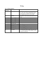
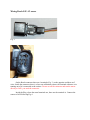
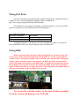
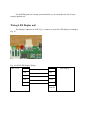
JAW 1.041 Hardware User Manual
Updated: Aug 30 2008
****Caution: The Heat sink on the left hand side of JAW gets very
hot. Please avoid touching it. JAW should be placed in an area
where there is good airflow.
Things to do before powering up JAW
Check the resistance between TP1 and TP2, underside of PCB
board, make sure the resistance is at-least 1k.
Check the resistance between TP1 and TP3, underside of PCB
board, make sure the resistance is at-least 1k.
Turn R_RPM, the variable resistor, to the most counter clockwise
position.
The Heatsink on the lm317t carries 0-12v, make sure it is does not
touch another voltage source.
Wiring
Fig. 1: Wiring Summary
Jaw 1.041
Connects to
Terminal #
1
12 [volt] Power
2
Ground
3
4
5
6
7
8
9
10
11
12
13
14
3-Bosch LSU
4- Bosch LSU
5- Bosch LSU
1- Bosch LSU
2- Bosch LSU
6- Bosch LSU
Gauge/voltmeter/NB
Gauge/voltmeter/NB
RPM Pickup
Analog input
EGT +ve
5v output
Notes
Should be connected to a power source that is
“live” only when vehicle is operational or when
accessories power is enabled. Wire should be
multi-stranded and rated for at least 3 amps
Wire should be multi-stranded and rated for at least
3 amps
0-5v analog output
0-5v analog output
Connects to tach signal
0-10v analog input
Positive end of k type thermocouple
You can tap this to power other 5v devices, keep
an eye on the temperature of the lm7805, you do
not want to over stress it.
Wiring Bosch LSU 4.2 sensor
Fig. 2
Fig. 3
On the Bosch connector there are 6 terminals; Fig. 3, on the opposite end there are 5
wires. Inside the connector, there is a laser cut calibration resistor, the terminal without a wire
running out of it is connected to the resistor. Do not cut off the connector and run the sensor
directly to JAW, you need the connector.
Inside the Plug, where the metal terminals are, there are the terminal #s. Connect the
sensor to JAW following Fig.4.
Fig. 4: JAW-Bosch LSU 4.2 Wiring
JAW Screw
Bosch Connector Terminal #
Terminal #
3
3
4
4
5
5
6
1
7
2
8
6
Wire Color leading to Head of Sensor
Grey
White
Yellow
Black
This is the contact that has no wire
directly leading to the sensor
Red
To connect to the sensor plug you can the terminal connections, Fig.5, which were sent to
you are part of the JAW kit. See “Wideband_Cable_Construction_Guide_Cheap_Method,pdf”.
Fig. 5
Alternatively you can order a harness, Fig.6, and use that. See
“Wideband_Cable_Construction_Guide_Expensive_Method.pdf”
Fig 6.
Use multi-stranded wires, rated for atleast 3amps for connecting the sensor to JAW.
Wiring EGT Probe
For EGT you need a k-type thermocouple, ideally it should be the “grounded” kind. An
example of a low cost EGT probe that is ideal for JAW is available here;
http://www.omega.com/pptst/BTH-000_BTH-090.html
The probe has 2 wires, negative and positive, usually the negative is a red wire and the
positive is a yellow wire. Wire the probe to JAW following Fig. 6.
Fig.6: JAW-EGT Wiring
Jaw Screw Terminal #
2 (ground)
13
EGT Probe
Negative, usually red colored
Positive usually yellow colored
Swapping the Negative and Positive wire will not damage the probe, so if you do not
know which end is which, you can try both ways and see which works.
Wiring RPM
Before you hook up the rpm signal, make sure R_RPM; the variable resistor Fig. 7,
is at the most counter-clockwise position possible. R_RPM is a current/voltage limiting
variable resistor. Turning the variable resistor clockwise, the resistance falls. Turning the
resistor counter clockwise will raise the resistance. R_RPM also forms a low-pass filter,
which will smooth out any spikes on the RPM signal. The higher the resistance the greater
the smoothing. The lower the resistance the less the smoothing. Always start off with the
highest resistance possible, if you notice that JAW is reporting too low of an RPM, then you
can lower the resistance until your RPMs read correctly.
Fig. 7
Never turn the variable resistor to the most clockwise position,
if you do so then will damage your JAW unit.
For the RPM signal you can tap your tachometer or you can tap the low side of your
primary ignition coil.
Wiring LED Display unit
The Display Connector on JAW, Fig. 9, connects to your first LED display according to
Fig. 10
Fig. 9
Fig. 10: JAW-LED Display Wiring
JAW 1.041
5v
5v
Gnd
Gnd
Data
Data
CLK
Clock
Enable
Enable
Data In
LED Display 1
For Daisy Chaining of up to 4 Display units, connect according to Fig. 11. The individual
wires are not shown, each line between boxes represents 5 wires; 5V, gnd, Data, Clock, and
Enable.
Fig. 11: Display Daisy Chain Wiring
LED Display 1
JAW
1.041
Data
In
Data
Out
LED Display 2
Data
In
Data
Out
LED Display 4
LED
Disp 3
Data
In
The Device connected nearest to JAW, LED Display 1, will show AFR/Lambda. The
second device on the chain, LED Display 2, will show EGT. The Third Device in the chain, LED
Display 3, will show positive boost pressure. The forth device in the chain, LED Display 4, will
Show RPM.
Currently there is no customization of the Display order possible. If you want to show
RPM then you must have 4 LED Displays attached, RPM will be shown on the last LED Display
of the chain. If you just want to show AFR/Lambda, all you need is one LED Display unit.
Sometimes the LED Display will glitch and you will get a very slow refresh. To fix this
problem you need to disconnect the Display unit, wait a few minutes until the capacitor of the
LED Display fully self-discharges, then reconnect the display. Alternatively you can disconnect
the display and short the “5v” pin to the “gnd” pin, which will ensure that the capacitor is fully
discharged and then reconnect the display. However, do not do not short the pins while the
display is connected to JAW or you will damage the JAW unit and/or LED Display. The glitch
usually occurs when a display is connected to JAW and/or each other while JAW is powered up.
The proper way to connect the LED Display to JAW and/or each other, is to power off JAW
first.
Data
Out
Onboard LEDs
There are 3 LEDs on the JAW 1.041 unit, Fig. 9. LED 3 indicates power. LED 1 and
LED 2 indicate Wideband sensor temperature according to Fig. 12.
Fig. 12: LEDs and Sensor Temperature
Sensor Temperature
LED 1
Too cool/Warming up
On
Perfect
Off
To Hot
On
LED 2
Off
On
On
When JAW is in firmware update mode, all 3 LEDs will be on.
Rescuing JAW from a bad flash update
If problems occur during a flash update; power failure, data validation failure,
disconnection of serial cable, etc…, and JAW is unable to accept another firmware update, you
can force JAW to accept another firmware update.
It is recommended that you disconnect the Bosch sensor when you are doing a firmware
update.
To force JAW into firmware update mode; press button “S1”, Fig. 7, while powering
JAW up. When you are in firmware update mode, all 3 LEDs will be on. Once in firmware
update mode, make sure that the next operation that you do is a firmware update via JAW Edit,
do not do things like “query device” or change settings etc…
Free Air Calibration
Free Air Calibration uses the known oxygen content of air, 20.9%, to calibrate JAW so to
be able to use aged sensors accurately. You must use Free Air, air that is not contaminated with
exhaust gases. The best way to do this is to physically pull out the Bosch oxygen sensor from the
exhaust.
Before Calibration, make sure the sensor is warmed up and at the correct temperature.
When the sensor is at the correct temperature, LED 1 will be off and LED2 will be on, Fig. 12.
By clicking the “Calibration” button in JAW Edit, JAW will perform a free air calibration
and save that calibration value to its internal memory. You can view the calibration value by
clicking the “Get CalVal” button. You can edit the “CalVal” value and overwrite the Calibration
value stored on JAWs internal memory by clicking the “Write CalVal” button.
For a perfect sensor the calibration value should be very close to 0. If the value is
negative that means that your sensor has the tendency to read too lean, the negative calibration
value is applied to each AFR/Lambda sample to richen it up. A positive calibration value means
that the sensor tends to read to rich, the positive calibration value is applied to each
AFR/Lambda sample to lean it out.
LED Display Unit Brightness
On each LED Display unit is a variable resistor, R2, which sets the brightness of the LED
Display. Turning the R2 clock wise will increase the brightness, turning it counter clockwise will
lower the brightness.
The limiting factor for how bright to set the display is the heat generated by the LM7805
voltage regulator, Fig. 13. The more LED Display units you daisy chain the more limiting the
heat generated from the LM7805 becomes.
You may put a heatsink on the LM7805 to deal with the heat, if so then you will want to
buy a heatsink for the “T-220” IC package. The metal tab of the LM7805 carries 5v, so if you
put a heatsink on it, make sure the heatsink does not touch another voltage source.
Fig. 13
9v Battery Connector
There is a 9v battery connector on JAW 1.041, it’s function is to supply JAW with power
for those who do not have a laptop available and want to; download settings and firmware
update, using a desktop computer. You can have a 9v battery and automotive 12v hooked up to
JAW at the same time, JAW will just use the automotive 12v. If 9v is the only power source, the
wideband sensor will not function as it draws too much current, everything else will function.