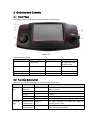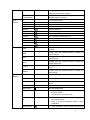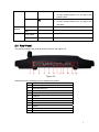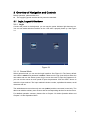
1
Network keyboard User’s Manual V1.1.0 Table of Contents 1 FEATURES AND SPECIFICATIONS ..................................................... VI 1.1 Features...................................................................................................................................vi 1.2 Specifications ..........................................................................................................................vi 2 OVERVIEW AND CONTROLS .................................................................1 2.1 Front Panel ...............................................................................................................................1 2.2 Function Buttons List ..............................................................................................................1 2.3 Rear Panel................................................................................................................................3 3 OVERVIEW OF NAVIGATION AND CONTROLS ....................................4 3.1 Login, Logout & Shutdown .....................................................................................................4 3.1.1 Login .....................................................................................................................................4 3.1.1.1 General Mode ............................................................................................................4 3.1.1.2 Matrix Mode ...............................................................................................................5 3.1.2 3.2 Shutdown .............................................................................................................................5 Admin Operation Menu...........................................................................................................5 3.2.1 Main Menu ...........................................................................................................................5 3.2.2 System Settings ..................................................................................................................6 3.2.2.1 General Settings........................................................................................................7 3.2.2.2 Network.......................................................................................................................8 3.2.2.3 Hardware Settings...................................................................................................10 3.2.2.4 Default.......................................................................................................................11 3.2.2.5 Screen Calibration...................................................................................................11 3.2.2.6 Backup ......................................................................................................................12 3.2.2.7 Version......................................................................................................................13 3.2.3 Device Manager................................................................................................................13 i 3.2.4 Input Settings ....................................................................................................................15 3.2.5 Output Settings .................................................................................................................17 3.2.6 Account ..............................................................................................................................18 3.2.7 Shutdown ...........................................................................................................................20 3.3 User Operation Menu............................................................................................................21 3.3.1 Main Menu .........................................................................................................................21 3.3.2 Device List .........................................................................................................................21 3.3.3 Input List.............................................................................................................................21 3.3.4 Output List..........................................................................................................................23 3.3.5 Remote Operation (Network Connection).....................................................................24 3.3.5.1 Shortcut Operation..................................................................................................25 3.3.5.2 Local Preview...........................................................................................................25 3.3.5.3 Decoder Operation..................................................................................................26 3.3.5.4 Playback of the decoder record ............................................................................28 3.3.5.5 PTZ............................................................................................................................29 3.3.5.6 Audio Talk ................................................................................................................30 3.3.5.7 Snapshot ..................................................................................................................31 3.3.5.8 Record ......................................................................................................................31 3.3.5.9 Remote Panel Simulation ......................................................................................33 3.3.6 3.3.6.1 The keyboard setup after COM Connection........................................................34 3.3.6.2 Operation..................................................................................................................35 3.3.7 Remote Operation (RS485) ............................................................................................36 3.3.7.1 The keyboard settings after PTZ connection ......................................................36 3.3.7.2 Operation..................................................................................................................36 3.3.8 Remote Control .................................................................................................................36 3.3.8.1 Local preview mode ................................................................................................37 3.3.8.2 Decoder Mode .........................................................................................................37 3.3.8.3 PTZ Control..............................................................................................................37 3.3.8.4 Menu Operation.......................................................................................................39 3.3.9 3.4 Remote Operation (RS232) ............................................................................................34 Advanced ...........................................................................................................................39 3.3.9.1 RS232 .......................................................................................................................40 3.3.9.2 Modify Password .....................................................................................................40 3.3.9.3 AUX Settings............................................................................................................41 3.3.9.4 Decode Settings ......................................................................................................41 3.3.9.5 MAC Settings ...........................................................................................................42 3.3.9.6 Snapshot ..................................................................................................................43 3.3.9.7 Backup ......................................................................................................................45 Matrix Mode Detailed operation ..........................................................................................45 3.4.1.1 Set Scheme..............................................................................................................47 3.4.1.2 PTZ Control..............................................................................................................49 ii APPENDIX TOXIC OR HAZARDOUS MATERIALS OR ELEMENTS ...........51 iii Welcome Thank you for purchasing our network keyboard! This user’s manual is designed to be a reference tool for the operation of your system. Here you can find information about this series network keyboard features and functions. Before the operation please read the following safeguards and warnings carefully! iv Important Safeguards and Warnings 1.Electrical safety All installation and operation here should conform to your local electrical safety codes. We assume no liability or responsibility for all the fires or electrical shock caused by improper handling or installation. 2.Transportation security Heavy stress, violent vibration or water splash are not allowed during transportation, storage and installation. 3.Installation Keep upwards. Handle with care. Do not place objects on the network keyboard 4.Qualified engineers needed All the examination and repair work should be done by the qualified service engineers. We are not liable for any problems caused by unauthorized modifications or attempted repair. 5.Environment The network keyboard should be used in a cool, dry place away from direct sunlight, inflammable, explosive substances and etc. 6. Accessories Be sure to use all the accessories recommended by manufacturer. Before installation, please open the package and check all the components are included. Contact your local retailer ASAP if something is broken in your package. v 1 FEATURES AND SPECIFICATIONS 1.1 Features z z z z z z z z z z z z z z z One network keyboard can control several DVRs or several network keyboards can control one DVR. Can control speed dome. Support RS485 and RS232 port. Support HDMI port. Support 2 USB ports. They are used to upgrade the applications, import/export configuration, backup snap picture and record files and etc. Support VGA output. Use the joystick to control the PTZ conveniently. Support all operations you get from DVR front panel function keys. Support keyboard lock function. Support multiple-level operation rights. Support menu setup of one or more DVR(s). 10.2-inch 800*480 TFT touch panel. On-screen menu, user-friendly interface, support touch pen for convenient operation. Control NVS, NVD. Built-in 10/100/1000M self-adaptive RJ45 port. Built-in WIFI module and external WIFI antenna, support wireless network connection. 1.2 Specifications Working Temperature 0℃-+55℃ Weight 4.5Kg Dimension (L*W*H.mm) 480mmx240mmx87mm joystick ) Working Power 12V, 3.33A LCD Dimension 10.2-inch (Excludes vi 2 Overview and Controls 2.1 Front Panel This series products’ front panel is shown as below. See Figure 2-1. Figure 2-1 It includes seven panes. SN Name SN Name 1 Touch panel 4 Shuttle(Outer ring) Jog(Inner dial) 2 Indication light 5 Function buttons 3 Record playback 6 PTZ control 7 Joystick 2.2 Function Buttons List Please refer to the following sheet for function button information. SN Name Symbol Function Function key Number and character 0-9 It is to input number and character. Click the Shift button to switch. Indication light ESC Cancel/exit ENTER Confirm SHIFT Switch LOCK Work with SHIFT button to lock/unlock the device. Working power indication light POWER The light becomes on when the keyboard connects to the power. Wire network indication light LINK The light becomes on when the keyboard connect to the wire network properly. 1 PTZ control Decoder DVR Buttons Indication light RX/TX The light becomes on when the wire network data is sending or receiving properly. Wireless indication light WIFI The light becomes ion when it connects to the wireless network properly. PT PTZ shortcut button GOTO Preset AUTO PAN Pan PATTERN Pattern ZOOM+ PTZ lens zoom in. ZOOM- PTZ lens zoom out. FOCUS+ Focus of the PTZ lens zoom in. FOCUS- Focus of the PTZ lens zoom out. IRIS+ Iris of the PTZ lens zoom in. IRIS- Iris of the PTZ lens zoom out. LIGHT Speed dome light shortcut button WIPER Speed dome wiper shortcut button. CAM Working with the number button to select the input channel. MON Working with the number button to select the output channel. WIN Working with the number button to select the output window. MULT Working with the number button to select the window split mode. CAM-G Working with the number button to select the input group. MON-G Working with the number button to select the output group. TOUR PTZ control, tour. MULT Window split mode. DEVC Working with number button to select remote device. Record z Stop record/playback. Stop record Play/pause Record/playback. f z z Backward/Pau se W z z Play previous z Play normally when it is backward playing or in pause mode. Play when it is in pause mode. Play backward when it is in normal playback or in pause mode. Click it to pause playback when it plays backward. When playback, click it to play the previous 2 z file. In menu setup interface, you can skip to the previous item. Play next z z AUX buttons AUX AUX button. Working with number buttons. MAC Macro setup. Others Touch panel Display OSD. Jog AUX menu or function buttons operation. When playback, click it to play the next file. In menu setup interface, you can skip to the next item. 2.3 Rear Panel This series products’ rear panel is shown as below. See Figure 2-2. Figure 2-2 Please refer to the following sheet for detailed information. 1 WIFI antenna 2 GND stud 3 RS422/RS485 port 4 Network port 5 VGA port 6 USB port 7 HDMI port 8 Audio output 9 Audio input 10 RS232 11 Power port 12 Power on-off button 3 3 Overview of Navigation and Controls Before operation, please make sure: z The supplying power and the device power are matched. 3.1 Login, Logout & Shutdown 3.1.1 Login Connect the power to the keyboard, you can see the power indicator light becomes on. You can see mode selection interface on the LCD after it properly boots up. See Figure 3-1. Figure 3-1 3.1.1.1 General Mode Select general mode you can see the login interface. See Figure 3-2.The factory default user name is admin and password is admin. Please turn the jog (inner dial) to select the user name and turn the shutter (outer ring) to move the cursor to input the password. Or you can use the mouse or touch panel to input the password. Click the SHIFT button to switch the input method. The input method includes number, capitalized character, small character and etc. The administrator account has only one user (admin) and the user name is read-only. The admin can add the ordinary user account and set corresponding devices for each account. For detailed operation contents, please refer to Chapter 3.2 Admin Operation Menu and Chapter 3.3 User Operation Menu. 4 Figure 3-2 3.1.1.2 Matrix Mode Select Matrix mode,you can see the following interface. Please input matrix information here. See Figure 3-3. Please refer to chapter 3.4 for detailed matrix mode operation. Figure 3-3 3.1.2 Shutdown After you logged out the system, you can press the power button to turn off the keyboard. 3.2 Admin Operation Menu 3.2.1 Main Menu After you login, the main interface is shown as below. See Figure 3-4. 5 It includes six buttons: General, Device manager, Input Settings, Output Settings, Account and Shutdown. Tips: After you login the menu, you can set the menu property. There are three ways for you. z You can set the device via the touch panel. z You can use the joystick to move the cursor or select the item. After you complete current setup, you can use the joystick to move the cursor to select other items. For special menu item, you can follow the prompt to click the ENTER button to confirm the operation or the ESC button to cancel current setup. z You can connect the mouse to the keyboard to use. Figure 3-4 3.2.2 System Settings The system settings include the following buttons: general, network, hardware, default, calibration, backup and version. See Figure 3-5. 6 Figure 3-5 3.2.2.1 General Settings In this interface, you can set system time, date, language, name and etc. It includes the Y-M-D-H-M-S setup. You can move your cursor to the corresponding position and then input. See Figure 3-6. z System time: Here is for you to set system time z Date format: There are three types: YYYYY-MM-DD: MM-DD-YYYYY or DD-MM-YYYY. z Date separator: There are three denotations to separate date: dot, beeline and solidus. z DST: Here you can set DST time and date. Please enable DST function and then click set button. Here you can set start time and end time by setting corresponding date/week setup. z Time format: There are two types: 24-hour mode or 12-hour mode. z Language: System supports various languages. You can select from the dropdown list. Please note system needs to reboot to activate current setup. z Device No.: Here you can input device number. z Device ID: Here you can input a name for current device. The network keyboard supports various input methods. You can use the corresponding input method to input a name. 7 Figure 3-6 3.2.2.2 Network There are two ways for you to select: LAN and WLAN. 3.2.2.2.1 LAN The wire network interface is shown as below. See Figure 3-7. You can use the direction keys and number keys to set. You can use the touch panel or the left/right button to move the cursor to the corresponding position and then use the number keys to change the setup. z IP address: Here you can input IP address. z Subnet mask: You can input subnet mask here. z DHCP: It is to auto search IP. When enable DHCP function, you can not modify IP/Subnet mask /Gateway. These values are from DHCP function. If you have not enabled DHCP function, IP/Subnet mask/Gateway display as zero. You need to disable DHCP function to view current IP information. Please note you need to have the router and enable the DHCP function before you use this function. z TCP port: Default value is 37777. z Preferred DNS server: DNS server IP address. z Alternate DNS server: DNS server alternate address. 8 Figure 3-7 3.2.2.2.2 WLAN The wireless network is shown as in Figure 3-8. z Click Refresh button, system begins search hotspot again and automatically add password information and etc (If you have added it in the past). z Select hotspot you want to connect and then click Connect button. The WIFI new hotspot setup interface is shown as in Figure 3-9. Please note you need to disconnect current connection if you want to connect again. z Click OK button, the WIFI working information can display current connection status after it successfully established the connection. See Figure 3-10. Figure 3-8 9 Figure 3-9 Figure 3-10 3.2.2.3 Hardware Settings The hardware interface is shown as below. See Figure 3-11. Here you can set key sound, key backlight, auto lock time, screen auto off time and etc. z Key Sound: Here you can check the box here to enable keyboard sound function. z Key Backlight: Here you can check the box here to enable keyboard backlight function. z Auto lock: Here you can set keyboard auto lock interval. The value ranges from 0 to 60. 0 means current function is disabled. z Screen auto off: Here you can set screen auto off interval. The value ranges from 10 0 to 60. 0 means current function is disabled. Figure 3-11 3.2.2.4 Default Here you can check the corresponding item to restore factory default setup. See Figure 3-12. Figure 3-12 3.2.2.5 Screen Calibration You can use the screen calibration function if the touch position is not accurate with the actual position. See Figure 3-13. Here you can view four + icons. Please follow the prompt in the screen to complete the calibration. Then you can see the corresponding prompt “Successfully calibrated.” 11 Figure 3-13 3.2.2.6 Backup From General settings->backup, the admin can go to the USB device backup list interface. See Figure 3-14. z Import: Please connect the USB device to the USB port and then check the box before the device name. Click the Import box to import the configuration. z Export: Please connect the USB device to the USB port and then check the box before the device name. Click the Import box to export the configuration. System can replace the original file if there are configuration files in the USB device. Important Please make sure you configuration file name is “config”; otherwise you can see a dialogue box says “Invalid configuration file.” Figure 3-14 12 3.2.2.7 Version In this interface, you can view system version, build date, SN information. You can also upgrade the system. See Figure 3-15. Please connect the device to the USB port and then click the Start button to begin the upgrade operation. Important Before the operation, please make sure your upgrade file name is update.bin. Figure 3-15 3.2.3 Device Manager Click Device manager button, you can see an interface shown as in Figure 3-16. Figure 3-16 The device manager interface is shown as below. See Figure 3-17. Here you can see controlled device name, IP address, port, device type, status and etc. You can add, modify and delete the device. 13 Figure 3-17 IP Search 1) Click IP search button, you can go to the IP search interface. 2) Please click the Refresh button to begin search and you can view the searched result in the IP search interface. 3) You can check the box to select a device and then input the user name and password, click the Add button to add a device. Important z Please make sure the device and the keyboard are in the same network section. Otherwise the search may fail. z After you searched the device, its initial status is null. You can view the device current status after you added it. System says the device has been added means it is in the Device manager list now. Add 1) Click Add button, system pops up the corresponding interface. 2) Here you can input manufacturer name, device name, IP address, port, user name and password. 3) Please click the Add button to add current device. You can see the corresponding dialogue box if you input information is wrong or current device is offline. You can not save the device on the keyboard if the add operation failed. 4) Click OK button to complete. 14 Figure 3-18 Modify and delete Modify: Select the device first and then click the Modify button, you can see system pops up an interface for you to change the information. Here you can modify device SN, port number, user name and password. See Figure 3-19. Important The user name and password here is for the keyboard to login the device. It does not change the user name and password of the keyboard itself. Figure 3-19 Delete Select the device you want to delete and then click the delete button, you can remove the device form the list. 3.2.4 Input Settings Click Input settings button, you can go to the following interface. Here you can view the device channel information you can control. See Figure 3-20. Important The position name is the corresponding channel name of the device. 15 Figure 3-20 Sync Click Sync button, you can system automatically synchronizes the channel name with the online device. See Figure 3-21. Figure 3-21 Modify Click the Modify button; you can go to modify interface. Here you can change serial number, main stream and extra stream, and protocol. See Figure 3-22. Important The SN of the monitor position name shall unique. Otherwise system may pop up a dialogue box “The channel name shall be unique. Please input again.” 16 Figure 3-22 3.2.5 Output Settings The output settings interface is shown as below. See Figure 3-23. Figure 3-23 Modify In Figure 3-23, click Modify button, you can go to the following interface to change the output SN. See Figure 3-24. Important Please make sure the output SN is unique. System may pop up a dialogue box says” Current input SN already exists, please input again.” 17 Figure 3-24 3.2.6 Account The keyboard account has two levels. One is admin and the other is ordinary user. The admin can add max 20 users. See Figure 3-25. z The admin account can set keyboard parameter, manage device and ordinary users. The device management rights include: add/delete/modify device. The user management rights include: add/delete/modify user, and set devices for each user. z The user account can only have the operation rights and control the assigned devices. Each ordinary user can max control 256 devices. Figure 3-25 Modify Password Please select an account and then click the Modify user button; you can go to the following interface. See Figure 3-26. Here you can change the password. 18 Figure 3-26 Add User Click Add user button, you can go to the following interface to add the new user. You need to input the user name and password. See Figure 3-27. Figure 3-27 Modify User Select an ordinary user from the list and then click the Modify user button; you can go to the following interface. Here you can add or delete the device current user controls. See Figure 3-28 and Figure 3-29. 19 Figure 3-28 Figure 3-29 3.2.7 Shutdown Click the Shutdown button; you can see system pops up a dialogue for you to confirm the operation. You can logout the menu, shutdown the device or reboot the system. See Figure 3-30. Figure 3-30 20 3.3 User Operation Menu 3.3.1 Main Menu The user menu is shown as below. See Figure 3-31. It includes: device list, input list, output list, remote operation, advanced and remote control. Figure 3-31 3.3.2 Device List The Device list is shown as below. See Figure 3-32. Here you can view the device that current user can control. Figure 3-32 3.3.3 Input List Here you can view the channel information of controlled device. See Figure 3-33. 21 Please note the position name is the channel name system gets from the device. Figure 3-33 Sync Click the Sync button; the device input list can synchronize the channel device monitor position name. See Figure 3-34. Figure 3-34 Group Click Group button, you can go to the following interface. See Figure 3-36. You can select the group SN and then go to the group interface. There are 16 input groups and you can add/delete the monitor positions. You can also se the tour interval. This operation is mainly for the decoder group. Please refer to chapter 3.3.5.3 Decoder Operation for detailed information. 22 Figure 3-35 Figure 3-36 3.3.4 Output List The Output list interface is shown as in Figure 3-37. Figure 3-37 23 Group Click Group button, you can go to the following interface. See Figure 3-38. You can select the group SN and then go to the group interface. There are 16 output groups and you can add/delete. Figure 3-38 Delete Check the corresponding box first and then click Delete button, you can delete the output port from the list. Add Click Add button, you can go to the following interface. See Figure 3-39. Please check the corresponding output port and then click the Add button. Figure 3-39 3.3.5 Remote Operation (Network Connection) 24 Basic operation z Keyboard lock: It is to lock the keys and mouse. The keys, joystick and touch panel are all null once you lock the keyboard. You need to click the unlock button to unlock the keyboard. z Keyboard lock/unlock button: Click LOCK+SHIFT button within 3 seconds. z The keyboard lock operation has the highest priority in the shortcut operations. During any operation in any interface, click the LOCK+SHIFT button, you can lock the keyboard. z Delete: During the keyboard remote operation, ESC button have the delete function. You can use it to remove the latest input number. Important The keyboard becomes lock after the screen auto turns off. 3.3.5.1 Shortcut Operation Remote operation You can view current selected output channel on the left pane. Here you can select window display mode, the decoded input channel of each window and set other shortcut ways. You can view current input information and some shortcut setups on the right pane. See Figure 3-40. Figure 3-40 3.3.5.2 Local Preview Local preview is to decode and playback the signal from the input channel at the keyboard local-end. You can implement other shortcut operations during the local preview process. Please follow the steps listed below. 1) Input number 0+MON, select the local preview operation. 2) Input number i+MULT, select the window display amount. System now supports 1/4/8/9 /16-window mode. 3) Input number j+WIN, select the output window j. 25 4) Input number k+CAM, it is to output the signal from the channel k to window j via the keyboard decode. For example, 0+MON+4+MULT+2+WIN+1+CAM means: Display in 4-window mode; output the video from channel 1 to the window 2 to preview. See Figure 3-41. Figure 3-41 Note Input Number j+WIN+0+CAM, it can stop local preview function of window j. Select one window and click (NEXT)or (PREV), you can increase or decrease the previous local decode video source number and then output it to current select window. 3.3.5.3 Decoder Operation Window split Mode Here is for you to set the window display mode. It is to output the selected channel to the specified windows. Please follow the steps listed below. 1) Input number i+MON, it is to select the output channel i. Please note 0+MON is the keyboard local preview. 2) Input number j+MULT, it is to output the signal from channel i to display in j-window mode. Output to the video wall It is to display the signal from the selected channel via the decode output channel. See Figure 3-42. Please follow the steps listed below. 1) Input number i+MON, it is to select output channel i. 2) Input number j+WIN, it is to select current output window. 3) Input number k+CAM, it is to output the input signal from channel k to the video wall 26 via the output channel i of window j. Figure 3-42 If you want to enable local video preview function, there are two ways: z Input number j+WIN to select window and click ENTER button, click ENTER button again to close current preview. z Input number j+WIN. Select one window and click (NEXT)or (PREV), you can increase or decrease current video channel number and then output it to current select window. Note Input number j+WIN+0+CAM, you can stop dynamic decode function of window j. Output decoded video group to the video wall (Input group->output channel). The function of the decoder is to output a selected group via the output decoded channel. Detailed function: z When the channel n in the group is smaller than the output channel window amount m, it is to decode dynamically. System outputs the input channel from the group to display in the windows respectively. z When the channel n in the group is larger than the output channel window amount m, it is to realize the tour function from group to screen. The output channel window m is one output group and system decodes and outputs the input channel m by once. System repeats the output until the remaining input channel amount is smaller than the m. Please follow the steps listed below. 1) Input i+MON, it is to select output channel i. 2) Input j+CAM-G, it is to output current input group j via the output channel i. 27 Decoded video group to the video wall (Input group->output window) You can refer to the above contents for detailed information. The difference is that you need to select a window for the output channel. You need to set the input channel of the input group to one window of the output channel to enable the tour function. If there is only one input channel, it is just like the dynamical decode in the output window. Please follow the steps listed below. 1) Input i+MON, it is to select the output channel i. 2) Input j+WIN, select the window j for current output channel. 3) Input k+CAM-G, select to output the current input group k to the output channel window j to enable the tour function. Decode video to the video wall (Input group->output group) You can refer to the above contents for detailed information. If the channel amount n in the input group is smaller than or equal to the output window amount m in the output group (for example, output group 1 has two output channels, and each output channel has 4-window. There is total 8-window. Here you need to compare n and 8.). It is to decode the signal from the input channel to the output channel respectively. If the n is larger than m, system decodes and outputs m output channel until the remaining input channel is smaller than m. Please follow the steps listed below. 1) Input m+MON-G, it is to select the output group m. 2) Input n+CAM-G, it is to output the input group n to the output group m to enable the tour function. 3.3.5.4 Playback of the decoder record It is to control the output channel to playback the record file of the decoded input channel remotely. You need to select the output channel and input channel and set the corresponding playback time. See Figure 3-43. Please follow the steps listed below. 1) Input i+MON, it is to select the output channel i. 2) Input j+WIN, it is to select the window of current output channel. 3) Input k+CAM, select input channel k. You can skip to the next step if current channel already decodes in current playback channel. 4) Click ► (PLAY/PAUSE), you can go to the decoder record file playback setting interface. (Right now, there is no playback in current window). 5) Set playback start time and end time. Please input the time (second-minute-hour) and select the day-month-year. Click the OK button to begin the playback. 6) During the playback process, you can click f (PLAY/PAUSE)to pause current operation, click ▀ (STOP) to stop playback. 28 Figure 3-43 If you click f(PLAY/PAUSE)or ▀ (STOP)without selecting a window, system begins or stops playback of the first window by default. Important Right now, system supports control decoder playback remotely. It does not support the local playback function. 3.3.5.5 PTZ In the PTZ control mode, you cam use the network keyboard to control the PTZ operation. The interface is the same as when you are controlling via the Web. You can view the video from the control channel on the left pane and the PTZ control interface on the right pane. You can input number i+PT to open PTZ operation interface. The number i is the channel number on the input list. The PTZ interface is shown as below. See Figure 3-44. 29 Figure 3-44 You can input the number (Step, preset and etc) from the panel. You can use the keyboard to control the PTZ, zoom, and use joystick to control the direction. You can also use mouse and touch panel. You can use the touch panel to control the positioning and PTZ. Please refer to the following sheet for detailed information. Button Function Number Input step, preset and etc. Joystick Control PTZ direction. Shuttle (Outer ring)/ Jog(Inner dial)/ / / / Zoom +/Focus +/Iris+/Light Wiper GOTO Preset PATTERN Pattern start /Stop TOUR Tour start /Stop AUTOPAN Pan start /Stop ESC Exit 3.3.5.6 Audio Talk You can use the audio talk function to realize the bidirectional talk between the keyboard and the selected device. See Figure 3-45. Here we use “a+AUX” to enable the audio talk function. See chapter 3.3.9.3 for audio talk function setup. In the local preview mode, you can follow the steps listed below. 1) Input number i+WIN, you can select channel of one device for current window. 2) Input number a+AUX, it is to enable the bidirectional talk with the selected window. Click AUX to stop the audio talk (bidirectional talk). Important In the local preview mode, input number a+AUX, you can enable the bidirectional talk with device in the first window. In any mode 1) Input number i+DEVC, it is to select device on the keyboard device list. 2) Input number a+AUX, it is to enable the bidirectional talk with the specified device. See Figure 3-45.Click AUX button again to stop the audio talk (bidirectional talk). 30 Figure 3-45 3.3.5.7 Snapshot The snap function can only be valid in preview mode. The snap picture saved in the USB device or a FTP server. Please refer to chapter 3.3.9.3 for snapshot setup. Please follow the steps listed below. 1) Input number i+WIN, it is to select the window i for the output channel. 2) Input a+AUX (Please make sure you have set a+AUX as the snap shortcut button) or button at the top of the joystick to enable network snap. If you click the snapshot shortcut button directly, system snapshots the video in the first window by default. 3.3.5.8 Record The USB device record has two types: local preview record and remote channel record. See Figure 3-46 and Figure 3-47. z Local preview record: During the preview process, select preview window to record. z Remote channel record: You can select an input a channel name to record. Please follow the steps listed below. z Local preview record: Input number i + WIN + REC (Please make sure you are in preview mode.).See Figure 3-46. 31 Figure 3-46 If you click the record shortcut button directly, system records the video in the first window by default. Remote channel record: Input number j+ CAM+ REC. See Figure 3-47. You can click ▀ (STOP) to stop record. Figure 3-47 Important z In anytime, system can only record in one mode. You can not enable these two modes at the same time. The remote record stops once you exit the remote control interface. z In the preview mode, click the REC button directly; system begins record the first window by default. 32 The local USB device record automatically stops when you switch the mode. The local record function can only be valid in the preview mode. When one record is in process, if you enable the other mode, you can see system pops up a dialogue box for confirmation. You can click the OK button to stop current record and then enable the new one. 3.3.5.9 Remote Panel Simulation In this mode, it works as the front panel. It simulates the front panel of the DVR. It supports shuttle/jog, number, record, playback, PTZ, OK, ESC and etc. Please follow the steps listed below. Input number i+DEVC+ENTER, you can begin remote panel simulation. Number i is the DVR SN in the Device manager interface or the device list. You can click the DEVC to exit. See Figure 3-48. Figure 3-48 Please refer to the following sheet for detailed shortcut button information. Button Function ENTER/Joystick button Main menu REC Record control PT Open the AUX function: PTZ control and color. z Play/pausef z Play normally when it is backward playing or in pause mode. Play when it is in pause mode. play/pauseW z Play backward when it is in normal playback or in pause mode. Click it to pause playback when it plays backward. Play previous z When playback, click it to play the previous file. Backward z 33 Play next z In menu setup interface, you can skip to the previous item. z z When playback, click it to play the next file. In menu setup interface, you can skip to the next item. Record Click the REC button, you can see Record interface. You can use the shuttle/jog to set the channel number and status. Click the ENTER button to save current setup and click the ESC button to exit. One-window/multiple-window mode switch Use the jog (inner dial) to select the window amount and use the shuttle (outer ring) to switch the displayed channel. Click the number button, you can see selected channel. For example, click number 1; you can see channel 1. If you input channel number is more than 10, you can work with the CAM button. The input method is CAM+channel number+CAM. For example, click CAM+12+CAM, you can go to channel 12. PTZ control and color In window-display mode, there are two ways for you to see the PTZ control interface. z Click the PT button in the keyboard to enable the AUX function: PTZ control and color. Select the PTZ control to see DVR PTZ control menu. z Input number i+PT (i=channel number), you can open the local PTZ control menu via the keyboard. 3.3.6 Remote Operation (RS232) 3.3.6.1 The keyboard setup after COM Connection Before the operation, please make sure: 1) The keyboard and the DVR connection are right. 2) The DVR settings are right. In the DVR main menu, from Setting->RS232, in the Function item, please select net keyboard from the dropdown list. You need to set the baud rate, stop bit, data bit, parity and etc. System default setup is: Baud rate:9600: Data bit:8, Stop bit:1, Parity: none. 3) For the keyboard, from the Advanced->COM, here you can input remote address, baud rate, data bit, stop bit and parity. Please note: z Remote address: It is a SN for the front-end to detect. It is the DVR No. in the General interface. You can use move the cursor to the remote address or use the shuttle(outer ring) to select the remote address, input the value directly or you can jog(inner dial) to select. z Please make sure the keyboard setups are the same with the DVR. 34 3.3.6.2 Operation In this mode, you can use the keyboard to control the DVR interface operation. It supports shutter (outer ring), jog (inner dial), number, record, playback, PTZ, confirm, ESC and etc. Important Please logout the DVR local menu user before you login since the DVR local user has the higher priority than the keyboard user! Please follow the steps listed below. Input number 0+DEVC+ENTER to control the front-end DVR interface operation. Click the DEVC button to exit. See Figure 3-49. Figure 3-49 Record Click the REC button, you can see the Record interface. You can use the shuttle/jog to set the channel number and status. Click the ENTER button to save current setup and click the ESC button to exit. One-window/multiple-window mode switch Use the jog (inner dial) to select the window amount and use the shuttle (outer ring) to switch the displayed channel. Click the number button to see the selected channel. For example, click number 1; you can see channel 1. If you input channel number is more than 10, you can work with the CAM button. The input method is CAM+channel number+CAM. For example, click CAM+12+CAM, you can see channel 12. PTZ control and color In window-display mode, there are two ways for you to see the PTZ control. z Click the PT button in the keyboard to enable the AUX function: PTZ control and color. 35 z Select the PTZ control to see DVR PTZ control menu. Input number i+PT (i=channel number), you can open the local PTZ control menu via the keyboard. 3.3.7 Remote Operation (RS485) 3.3.7.1 The keyboard settings after PTZ connection Before the operation, please make sure: 1) The A, B cable of the keyboard properly connects to the A, B cable of the speed dome. 2) Turn on the speed dome and connect the video cable to the monitor. 3) Set the speed dome address. Please make sure your keyboard RS485 address shall be the same with the speed dome address here. 4) In the keyboard menu, from the Advanced->PTZ, you can set protocol, address, baud rate, data bit, stop bit, parity and etc. You can select the protocol according to your speed dome and RS485 address is the same as the speed dome. 5) Please save current setup. 3.3.7.2 Operation In this mode, you can use the network keyboard to control the PTZ of the speed dome. Please input the number 0+PT to enable PTZ control. Please refer to chapter 3.3.5.5 Pan/Tilt/Zoom for detailed information. 3.3.8 Remote Control Remote control interface is shown as in Figure 3-50. Figure 3-50 Please refer to the following sheet for detailed information. 36 SN Name Function ① Preview You can preview in the pane. ② Input/output list You can select input channel and output channel in the pane. ③ Window split Set window display mode in current pane. ④ Full screen Click it to preview in full-screen. ⑤ PTZ control Click it to realize PTZ control. ⑥ Menu Click it to record, snapshot and etc. ⑦ Device information Click it to view connected device information. Important Except PTZ control and record/snapshot function of the local preview mode can use button, joystick, shuttle, the rest functions listed here do not support shortcut button. 3.3.8.1 Local preview mode Local preview is to decode and playback the input channel signal on the keyboard. Please follow the steps listed below. 1) From output list, network keyboard->local preview, and then double click local preview. 2) Select window display mode on the window split pane. 3) Select a window; double click an input channel on the input list or you can drag one channel to a window directly. Now you can preview the video from the selected channel on current window. 3.3.8.2 Decoder Mode On the decoder mode, the video from one input channel can be decoded and then output to an output channel. Please follow the steps listed below. 1) Double click an output channel from an output list. (Not local preview). 2) Select window display mode on the window split pane. Important The screen of the decoder will change window display mode at the same time. 3) Select a window; double click an input channel on the input list or you can drag one channel to a window directly. You can go to to open preview if you want to enable keyboard local preview function. Now you can view the input channel video on current window. 3.3.8.3 PTZ Control Important You can only control PTZ after you open preview interface. 37 In the PTZ control mode, you cam use the network keyboard to control the PTZ operation. The interface is the same as when you are controlling via the Web. You can view the video from the control channel on the left pane and the PTZ control interface on the right pane. The PTZ interface is shown as below. See Figure 3-44. Figure 3-51 You can input the number (Step, preset and etc) from the panel. You can use the keyboard to control the PTZ, zoom, and use joystick to control the direction. You can also use mouse and touch panel. You can use the touch panel to control the positioning and PTZ. Please refer to the following sheet for detailed information. Button Function Number Input step, preset and etc. Joystick Control PTZ direction. Shuttle (Outer ring)/ Jog(Inner dial)/ / / / Zoom +/Focus +/Iris+/Light Wiper GOTO Preset PATTERN Pattern start /Stop TOUR Tour start /Stop AUTOPAN Pan start /Stop ESC Exit 38 3.3.8.4 Menu Operation The menu interface is shown as in Figure 3-52. Figure 3-52 z Start record: Click it to record current preview video. Or you can click z(REC) to record. Please note you need to insert flash disk before you begin record operation, otherwise you can not record. The record files will be saved on the flash disk. z Snapshot: Click it to snapshot current video and save as one picture. You can press button at the top of the joystick to snapshot. The picture can be saved on the flash disk or on a FTP server. For detailed snapshot setup information, please refer to 3.3.9.3 chapter z Close preview: Click it to close current preview video. z Close window: Click it to close current window. z Close all: Click it to close all windows. z Open all: Click it to open all windows. 3.3.9 Advanced The advanced interface is shown as below. See Figure 3-53. It includes: RS23, modify password, AUX, decode, MAC, snapshot, and backup. 39 Figure 3-53 3.3.9.1 RS232 Click RS232 button, you can go to the following interface. See Figure 3-54. Here you can set remote address, baud rate, data bit, stop bit, and parity. Figure 3-54 3.3.9.2 Modify Password The modify password interface is shown as in Figure 3-55. Here you can change the password of current user. Please input the old password first, and then input the new password and confirm. You can click OK button to save new password. See Figure 3-55. 40 Figure 3-55 3.3.9.3 AUX Settings The AUX settings interface is shown as below. See Figure 3-56. The aux button ranges from 0 to 9. The shortcut operation supports audio talk and the snap. You can select the AUX button and click the OK button to realize the corresponding function. You can input the corresponding number+AUX to enable the function. See Figure 3-56. Figure 3-56 Important System default AUX button is 0; you can click it to enable snapshot function and 1 is audio talk (bidirectional talk) function. 3.3.9.4 Decode Settings The decode settings interface is shown as in Figure 3-57. You can select the channel name and decode type from the dropdown list. 41 Figure 3-57 The type includes: RT (real-time) priority, RT good, general RT and fluent (default), fluent good, fluent priority. See Figure 3-58. Figure 3-58 3.3.9.5 MAC Settings The MAC interface is shown as below. See Figure 3-59. Here you can enjoy a shortcut to implement a series of operations. When the user is in the remote operation mode, click the previously set “Number+keyboard MAC” button, you can call the specified macro. 42 Figure 3-59 Click Add button, you can go to the following interface. You can input customized macro name one by one and then click the Save button. See Figure 3-60. Important For the macro already exists, it is read-only. Some keys do not support macro. Figure 3-60 3.3.9.6 Snapshot In this interface, you can save snapshot picture on a FTP server. Please follow the steps listed below. 1) Click Snapshot button on the Advanced interface. You can see an interface shown as in Figure 3-61. 43 Figure 3-61 2) Check the Enable box in Figure 3-61 to open snapshot function and input FTP server IP, port, username, password and etc. See Figure 3-62. Figure 3-62 Please note: If you do not check the Enable box here, system does not connect to the FTP server. At the same time, if you have inserted a flash disk, all the snapshot pictures will be saved on the flash disk. If the FTP service and flash disk are both available at the same time, the FTP has the higher priority. That is to say, all snapshot pictures will be saved on the FTP server. The snapshot function is null if the FTP service and the flash disk are not available at the same time. 44 3) Click Test button, system begins FTP test. You can see connection is OK once you see the following interface. See Figure 3-63. Figure 3-63 4) Click OK button on Figure 3-63 and Figure 3-62, you can complete snapshot function. 3.3.9.7 Backup In this interface, you can set pre-record time of the monitor video. Please follow the steps listed below. 1) Click Backup button on the Advanced interface. You can see an interface shown as in Figure 3-64. Figure 3-64 2) Input pre-record value (such as 0 s to 5s) and click OK button to complete setup. 3.4 Matrix Mode Detailed operation Matrix mode interface is shown as in Figure 3-65. 45 Figure 3-65 In this interface, the control tour and close preview operation of is for the whole selected area. Click number 0+MON is to close all video source on the selected screen, and at the same time system updates the contents of the screen such as window split mode, tour time and etc. Double click the splicing video wall you want to operate or input number i+MON on the keyboard, you can see an interface shown as below. See Figure 3-66. Figure 3-66 46 Please refer to the following sheet for detailed information. SN ① ② ③ ④ ⑤ ⑥ ⑦ Name Function Preview Real-time display screen, window, video source, tour and etc. Input/output setting Here is for you to implement scheme operation. Return Click it to return TV wall. Window split It is for you to set preview window display mode. PTZ Click it to realize PTZ control. Menu Implement tour control and close preview operation. Device information Click it to view device information or scheme SN. Here is to open all the contents you set on the matrix end. Click number 0+MON on the keyboard is to close all video sources of current screen. 3.4.1.1 Set Scheme Scheme is for you to set video wall information such as window display mode, video source information, tour setup and etc. Split mode: In this pane, you can set different window display modes. You can also click number j+MULT to operate. There are two situations: z You have selected a screen under the scheme mode, but there is no display, input number j+MULT to update screen contents. z Once you switch to one screen, input number j+MULT, you can see screen display on j-window. Video source information: Click See Figure 3-67. , you can switch to input list interface. 47 Figure 3-67 1) 2) Use mouse, touch panel or the keyboard to input number j+WIN to select one window. There are three situations: If there is no screen available, system switches to screen that contains this window and set this window as current one. If there is a screen available and the window is in current screen, set this window as current one. If there is a screen available but the window is not in the screen, then system switches to the screen that contains the window and set this window as current one. Input number k+CAM on the keyboard or select one channel and drag it to the window you selected in the first step; you can output the video to the window you specified at the matrix end. Or you can drag whole customized folder to the window, or click number k+CAM-G on the keyboard to output a group of video sources to the TV wall. Select one window, click close preview of the of the output channel of the decoder. Select one window, click (NEXT)or , system closes the preview video (PREV), you can output the previous or next video source to the selected window. Tour setup: In the Input and output setup interface, you can set tour time. When input the customized folder and the channel amount on the folder is larger than the output channel amount, system enables tour automatically. See Figure 3-68. 48 Figure 3-68 Click the control tour of the or click the TOUR on the keyboard, you can close the tour of the whole screen. Click Control tour or TOUR button again, you can enable tour function again. Please note: z On the Apply mode, all matrix setups can be changed automatically once you change the keyboard setup. z On the output all mode, except window split mode, the rest setup can only be applied to the matrix end once you set on the keyboard and click output video button. Click save scheme button, you can save current scheme setup. If you have not save, click reload button, you can go back to previous setup. Click Close video button, you can close splicing video on the matrix end. 3.4.1.2 PTZ Control In the PTZ control mode, you cam use the network keyboard to control the PTZ operation. The interface is the same as when you are controlling via the Web. You can view the video from the control channel on the left pane and the PTZ control interface on the right pane. Click button, the PTZ interface is shown as below. See Figure 3-44. 49 Figure 3-69 You can input the number (Step, preset and etc) from the panel. You can use the keyboard to control the PTZ, zoom, and use joystick to control the direction. You can also use mouse and touch panel. You can use the touch panel to control the positioning and PTZ. Please refer to the following sheet for detailed information. Button Function Number Input step, preset and etc. Joystick Control PTZ direction. Shuttle (Outer ring)/ Jog(Inner dial)/ / / / Zoom +/Focus +/Iris+/Light Wiper GOTO Preset PATTERN Pattern start /Stop TOUR Tour start /Stop AUTOPAN Pan start /Stop ESC Exit 50 Appendix Toxic or Hazardous Materials or Elements Component Name Toxic or Hazardous Materials or Elements Pb Hg Cd Cr VI PBB PBDE Device Construction Material ○ ○ ○ ○ ○ ○ Circuit Board Component ○ ○ ○ ○ ○ ○ Wire and Cable ○ ○ ○ ○ ○ ○ Accessories ○ ○ ○ ○ ○ ○ O: Indicates that the concentration of the hazardous substance in all homogeneous materials in the parts is below the relevant threshold of the SJ/T11363-2006 standard. X: Indicates that the concentration of the hazardous substance of at least one of all homogeneous materials in the parts is above the relevant threshold of the SJ/T11363-2006 standard. Note: z This manual is for reference only. Slight difference may be found in the user interface. z All the designs and software here are subject to change without prior written notice. z All trademarks and registered trademarks mentioned are the properties of their respective owners. z If there is any uncertainty or controversy, please refer to the final explanation of us. z Please visit our website or contact your local retailer for more information. 51