1
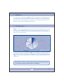
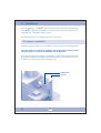
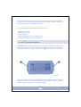
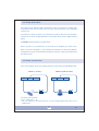
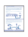
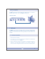
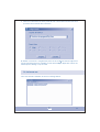
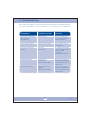
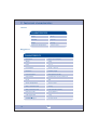
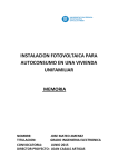
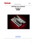
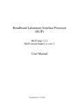
User Manual Contents 1.- Preface 02 2.- Introduction 02 3.- Safety Warnings 03 4.- Components 03 5.- Installation 05 5.1.- Receiver installation 05 5.2.- Pixy module installation 06 07 6.- Operation 6.1.- Test Button 07 6.2.- Operation LEDs 07 6.3.- Audio alarm signal 07 6.4.- Relay activation 08 6.5.- Relay connection 08 6.6.- Connection to Previstorm 09 6.7.- Connecting various secondary modules 09 6.8.- PC Connection 10 10 7.- Software 7.1.- Software installation 10 7.2.- Software use 12 7.2.1.- Program menus 13 8.- Troubleshooting 14 9.- Technical characteristics 15 01 1. Preface First of all, thanks for choosing our Pixy . This product is the result of our broad experience in the research of lightning phenomena, and the development of preventative and protective systems. In 1973 Ingesco embarked on the journey that has allowed us to provide our clients with integral lightning protection. 2. Introduction Pixy is a cloud to earth atmospheric discharge detector for lightning detection and prevention systems. Pixy detects atmospheric discharges within an approximate 15 km radius which allows the detection of approaching storms and the activation of protection and alarm systems. Approx. Radius: 15 km You should not wait for a signal from Pixy to take preventative or protective actions. If the climatic conditions are considered dangerous to your facilities or personnel and Pixy has not given any alert signal, do not hesitate to take the predetermined actions electric risk. Please read this manual carefully before placing this product in service and if you have any doubts, please contact your distributor. 02 3. Safety Warnings Do not damage the power cable, no place heavy objects on the equipment. Treat the equipment with care. Avoid knocks and vibrations. Before moving the equipment, disconnect the power cable. If noises, vibrations or abnormal odors are detected coming from the equipment, immediately disconnect the power cable. Contact your official distributor. Do not handle the equipment with wet or moist hands in order to avoid the risk of electric shock. Always use genuine cables and parts. 4 . Components Fig. A (Antenna) Fig. B (Pixy Module) Fig. D (Serial cable) Fig. E (Power supply) Fig. C (Antenna cable) Fig. F (Instruction manual) Ma nua Fig. G (Installation CD) Ensure that all of the articles are included in the package. 03 l usu ario 3 Fig. A (Antenna) 1 - Allen screw. 2 - Antenna cable connector. 3 - Protector radome. 1 2 Fig. B (Pixy Module) 4 - Fastening holds 4 5 - Antenna Connector DIN 5 via Stereo 6 - Operation LED 7 - Primary/secondary connector 8 - PC serial connector 9 - Output relay 1(10 sec.) 10 - Indicating LEDs 11 - Output relay 2 (End of storm) 12 - Previstorm Connector 13 - 12V power connector 14 - Audio switch 15 - Test button 4 5 6 7 10 8 14 9 11 15 12 13 04 5 . Installation The entire installation of the Pixy consists of the placement of the antenna, the fastening of the Pixy module, and the different connection options that are available on the equipment (PC, secondary modules, relays...) The following explains the installation process in more detail. 5.1 Receiver installation Install the antenna outside, in an area which is clear of obstructions in all directions. The antenna does not need to be installed in the highest place in order to detect lightning signals as it functions as detection and not attraction. The antenna should be fastened to a cylindrical mast with a 50mm exterior diameter. This should be selected according to the implementation of the capture device, that is, whether on a base plate or with a separation arm. Pixy Module Antenna 05 Do not install the antenna in areas that are susceptible to atmospheric discharges or on structures which are classic targets for discharges; whether direct or indirect (TV antennas, telephone lines, tall trees, power lines.) To avoid false alarms avoid installing the antenna near: - Large metallic masses - Televisions or monitors - Fluorescent lights - Electricity generators, lifts, air conditioning units. - Spark sources (Solderers, Electric laboratories,...) 5.2 Pixy module installation The Pixy module should be installed indoors in an easily accessible area with a clear view of the light indicators. This module comes prepared to be installed vertically or horizontally whether on a wall or flat service. Fig. H shows the mounting holes. A B * Easy installation with m-6 metric screwdriver. Fig. H It is recommended to use an uninterruptible power supply (UPS) to ensure continued service in the event of a power failure. As an example, a 500Va UPS with a capacity of 7A/h provides almost 2 days of autonomous power. 06 6. Operation Pixy is a system which detects electro-atmospheric discharges within a radius of 15 km. The LEDs light to indicate electrical activity in real-time. All LEDs on indicates the maximum electrical storm risk and the consequent activation of the relays of the Pixy module. As the electrical risk gradually diminishes, the LEDs sequentially switch off. 6.1 Test Button The test button (Fig,B n_15) is used to check the proper operation of the Pixy module. Pressing this button activates all of the LEDs as well as the audio signals. Consecutively, they will each turn off at intervals of 2 seconds. In reference to signal activation, pressing the Test button implies that Relay 1 will remain active for 10 seconds and Relay 2 will be active until all LEDs are unlit. The Previstorm signal will give a 5V signal and a serial test signal will be sent to the PC. 6.2 Operation LEDs This LED indicates the unit is operating. A continuous blinking signifies proper operation. A non-blinking light or no light at all signifies incorrect power. 6.3 Audio alarm signal When electric activity is detected, an intermittent audio signal is emitted for 10 seconds. This can be suspended by turning the audio signal switch to OFF. (fig B,nº 14) 01 07 6.4 Relay activation The equipment is designed with 2 power-free output connections to interact with external processes such as audio-luminous alarms, power generators, UPS, GSM-GPRS modems etc. The purpose of these contacts is to automate any type of process or preventative measure in the event of lightning strikes or storm risks which need a digital warning signal. The Pixy module provides two output relays: Relay 1 (Fig B nº 9) is activated for 10 seconds at the beginning of every storm. Relay 2 or end of storm (Fig B n_11) is activated in the presence of electro-atmospheric discharges and does not deactivated until the risk of electric activity is terminated and the LEDs are unlit. 6.5 Relay connection The recommended connection diagram and the contact status are described below: RELAY 1 (10 sec.) NA COM NC RELAY 2 (End of storm) NA COM NC The relays are power-free. Vmax= 250V, Imax = 5A * For your safety it is recommended to not use voltages higher than 48V in your applications. 08 6.6 Connection to Previstorm The Pixy module is designed to send a lightning detection signal to the Previstorm storm detector system. The combination of both sensors (one for the electromagnetic field and the other for the electrostatic field) allows the Previstorm to confirm the lightning strike by this signal which, along with the continued real-time measurement of the electrostatic field system, is capable of providing highly reliable lightning detection and storm risk prevention. The signal provides a 5 Volt signal for .1 a second each time the Pixy module detects lightning. Connection schematic ANTENNA P/S SERIAL RELAY 1 RELAY 2 5V 12V 6.7 Connecting various secondary modules The Pixy module permits optional primary / secondary connection. By means of connector P/S and 485 serial cable the primary module can signal another secondary module allowing this one to monitor and activate of electronic output in another physical space. The maximum recommended distance between modules for this type of connection is 500 meters. Connection schematic COM SECONDARY ANTENA E/M SERIE RELE 1 RELE 2 5V PRIMARY 12V ANTENA E/M SERIE E/M SERIE RELE 1 RELE 2 5V 12V RS - 485 COM COM SECONDARY ANTENA 09 E/M SERIE RELE 1 RELE 2 5V 12V SECONDARY ANTENA RELE 1 RELE 2 5V 12V 6.8 PC connection The Pixy module permits monitoring and history logging by way of a computer. A DB9 serial cable is used to connect the Pixy modules to the PC. Connection scheme ANTENNA P/S SERIAL RELAY 1 RELAY 2 5V 12V COM 7. Software The Pixy module can be connected PC. With this connection and the software provided, the current status of the equipment can be monitored. Additionally, all incidents are automatically saved to the log file where all of these instances are recorded. 7.1 Software installation 1. Insert the CD in the computer. 2. If the program does not start automatically, go to the My PC icon and select the CD unit and double click on the Pixy icon. 3. Select the destination folder where the program is to be installed. By default, it is installed in C: Pixy View program documents. If you would like to change the location, press the change directory button and choose the desired location. 10 4. Write the name of the group of programs where the Pixy will appear in the start menu. By default, the name will be Pixy View. 11 5. Select the folder where the history data files are to be stored and select the serial port that is to be used for the connection. By default it is stored in C: Programs\Pixy View. The PC COM ports will also appear as well as indicating which are available for use with the Pixy application. Select the desired port by clicking on top of COM. 7.2 Software use Once the software is installed, we see the following window: 12 The text box provides real-time information on the status of the application. The following messages may appear: "Test OK.": You can check that the connection of the Pixy module to the PC is correct by pressing the Test button (Fig, B n_1 5). After pressing this button this message will appear in the text box in the connection test has passed. "Application initiation.": Records when the application started. "Proper connection.": No problems in the connection. "No connection.": A connection could not be established. "Activated alarm.": Electrical activity danger "Deactivated alarm.": Disappearance of electrical activity danger. "Application end.": Marks the quitting of the application. 7.2.1 Program menus Once the program is launched, 3 different menus are shown: File: This menu is used to open previously saved files for consultation and to quit the program. Tools: This menu permits the configuration of the directory where the history logs are saved and the selection of the COM port which comes from the Pixy module and goes to the computer. See part 5 of point 7.1 ?: This menu displays a brief description of the software, such as the version and origin (help.) 13 8. Troubleshooting Shown below is a table of common errors, their symptoms and possible solutions. For more information do not hesitate is contacting your distributor. Symptoms Possible causes Solutions The Operations LED doesn't blink or remains permanently lit. Defective power Check the power cable. Check that the adapter functions correctly. Can not hear the signal. Audio signal deactivated Place the audio switch to ON. (Fig B nº14) The relay outputs did not activate. Broken relay Bad contacts Do no apply power superior to 5A nor voltages to 250V. Check the cable connections. Verify power to actuators. Undesired detections. Electromagnetic disturbances Cable in bad condition Move the antenna away from electromagnetic interference. Check the condition of the antenna cable. Absence of detections. Capture device in bad condition Cable in bad condition Check that the capture device is in good condition. Check the condition of the antenna cable. 14 9. Technical characteristics ANTENNA CHARACTERÍSTICS Height 34 cm Diameter 19,2 cm Weight 1570 g. Operational temperature -30ºC to 60ºC Pixy MODULE CHARACTERISTICS 15 Dimensions 25,5 x 12,7 x 3,8 (cm) Weight 508 g. Power 12 V cc Consumption 90 mA - 150 mA Protection Transitory surge Communication Serial (RS-232, RS-485) Output relays Potential-free, 5A max, 250V max Mount Wall Service temperature -30ºC to 60ºC Relay 1 activation time 10 seg. Relay 2 activation time End of electrical activity Detection radius 15 km (approx.) Audio signal time 1 seg. Previstorm signal 5V max. 20 mA Dena Desarrollos, S.L. Duero, 5 08223 Terrassa (Barcelona) Tel: (+34) 93 736 03 00 Fax (+34) 93 736 03 03 [email protected] www.ingesco.com