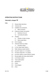
1
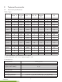
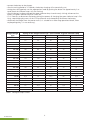
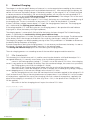
AXIgo
TRACTION BATTERY CHARGER
SERVICE MANUAL
4 5093 00 3
AXIgo
TRACTION BATTERY CHARGER
Content
1
1.1
1.2
1.3
1.4
1.5
1.6
1.7
1.8
2
2.1
2.2
2.3
3
3.1
3.2
4
5
5.1
5.2
6
7
8
Basic Data .............................................................................................................. 2
Device Characteristics .............................................................................................. 2
Usage ...................................................................................................................... 2
The Marking System of the AXIgo-type chargers ...................................................... 2
Standards ................................................................................................................. 2
Operational Safety ................................................................................................... 2
Supplies and Storage ............................................................................................... 3
Service ..................................................................................................................... 3
Abbreviations used ................................................................................................... 3
Technical Characteristics ....................................................................................... 4
Technical Specifications ............................................................................................ 4
Installation of the Charger ........................................................................................ 5
Description of Charger Control and Signalling .......................................................... 6
Setting of the Charger ...................................................................................... 6
Setting of the Output Current and the Selection of the Charging Characteristics ...... 6
How to Find Out the Current Setting ....................................................................... 7
Charger Functions, Charging Procedure ............................................................. 8
Standard Charging ............................................................................................... 9
IUIa Characteristic .................................................................................................... 9
IUa Characteristic .................................................................................................... 10
Battery Regeneration Mode ................................................................................. 10
Charger Maintenance ............................................................................................ 11
Alarm signalling .................................................................................................... 11
4 5093 00 3
1
1
Basic data
1.1 Device characteristics
The AXIgo-type chargers are intended for industrial applications, mainly for charging traction batteries for
electric high lift trucks and manipulation and cleaning technology devices. With regard to the perfect electric
parameters, they are suitable even for different types of batteries (e.g. maintenance-free batteries, gel batteries, AGM etc.).
The whole model range is shown in the Chart 1.
The rated (maximum) charging current is in the range of 25 – 200A. The standard output voltage is 12 –
96V, a different one on request. The respective types enable to set the output current in a step operation in
the range of c. 50-100% Inom. The AXIgo chargers use the principles of high-frequency technology. They
are based on power units operating in a high switching frequency, with the efficiency of up to 94 %. The
charging is either a one-phase one, or a three-phase one.
The charging process is controlled by a microprocessor control system. Important statuses are indicated by
indicator lamps.
According to their dimensions, the AXIgo chargers are installed into three types of boxes – S, M, L (see
chapt. 2.1)
1.2 Usage
The chargers are designed to be used in interiors with standard conditions (humidity, temperature, dustiness). When operated in a place with a higher level of dustiness, the interval of service inspections must be
shortened.
They should be connected to one-phase or three-phase power mains with a standard moveable lead cable
with a three-pole or a four-pole connector. The suitable protection must be carried out in the installation of
the charging station.
They are intended for cycle charging of traction batteries and they can be continuously operated. Cooling is
provided by fans placed inside the charger.
1.3 The marking system of the AXIgo-type chargers
AXIgo aa-bb
aa
rated output voltage, types 24, 36, 48, 72, 80, 96V
bb
rated output current 25-200A
Examples of the marking:
AXIgo 24-30
voltage 24V, current 30A, box S
AXIgo 48-50
voltage 48V, current 50A, box M
AXIgo 80-55
voltage 80V, current 55A, box L
1.4 Standards
The AXIgo chargers meets the requirements of the following standards:
EN 60950-1: Information Technology Equipment - Safety
EN 61000-6-2: EMC – Immunity for Industrial Environments
EN 61000-6-4: EMC – Emission Standard for Industrial Environments
CSN 33 2000-4-41: Electrical Devices - Safety
1.5 Operational safety
The following requirements must be met during the operation of the chargers:
- during the charging process, the chargers must be placed in well-ventilated rooms;
- the chargers must be connected only to the standard power mains;
- it is necessary to avoid sparking and making a fire near the battery; explosion hazard during the process of
charging;
4 5093 00 3
2
- the chargers must not be operated without a cover, an electric shock hazard
- only batteries intended for charging with the parameters (voltage, capacity ranges) suitable for the specified type of charger can be charged;
- during charging, it is dangerous to touch the supply leads to the battery poles;
- the transport of the charger during the charging process is prohibited;
- the supply leads to the battery must not be disconnected during the process of charging;
- the charger can be operated only by a respectively qualified person
- any changes in parameters can be made only by an authorized technical engineer.
1.6 Supplies and storage
The charger is supplied in a completed condition, with Operating Instructions. Normally it is supplied without
connectors (except for the 1-phase power supply) with the 2m-long outgoing cables.
A functional test is carried out with every charger.
The charger must be transported in the original package, the position during the transport can be arbitrary.
It is permitted to store the chargers in roofed, dry rooms, with the temperature from -25 °C to +80 °C, relative humidity up to 95 %, non-condensing.
1.7 Service
If a fault of the charger occurs, contact your retailer. On no account should the charger be repaired on your
own. The service of the chargers is provided by AXIMA, spol. s r.o., Vídeňská 125, 619 00 Brno, Czech Republic.
1.8 Abbreviations used
Ah
Cnom
Inom
Ichar
Unom
4 5093 00 3
ampere hour
rated battery capacity
rated current of the charger
set current at the top of the charging characteristics, in the range of 2,00 - 2,4V/cell
rated charging voltage
3
2
Technical characteristics
2.1 Technical specifications
Table of types
AXIgo type
Nom. input Max. outvoltage (V) put current
(A)
Mains
(VAC) **
Input current (A)
External
protection
(A)*
Case
Weight
(kg)
12-30
12
30
230
1,7
6
S
3,7
12-60
12
60
230
3,5
6
M
6,6
24-30
24
30
230
3,5
6
S
3,7
24-60
24
60
230
7,2
10
M
6,6
24-100
24
100
3x400
4
6
M
8,8
24-200
24
200
3x400
8
10
L
17,0
36-30
36
30
230
5,4
10
M
6,6
36-55
36
55
3x400
3,3
6
M
8,8
36-110
36
110
3x400
6,6
10
L
17,0
36-165
36
165
3x400
9,9
16
XL
26,0
48-30
48
30
230
7,2
10
M
6,6
48-50
48
50
3x400
4
6
M
8,8
48-100
48
100
3x400
8
10
L
17,0
48-150
48
150
3x400
12
16
XL
26,0
72-27
72
27
3x400
3,2
6
M
8,8
72-55
72
55
3x400
6,6
10
L
17,0
72-80
72
80
3x400
9,9
16
XL
26,0
80-27
80
27
3x400
3,6
6
M
8,8
80-55
80
55
3x400
7,3
10
L
17,0
80-80
80
80
3x400
10,8
16
XL
26,0
96-25
96
25
3x400
4
6
M
8,8
96-50
96
50
3x400
8
10
L
17,0
96-75
96
75
3x400
12
16
XL
26,0
* External protection - circuit breaker char. C nebo D
** Mains tolerance +15% -10%, 1phase chargers ± 15%.
Charasterictic
Starting current
<10 A, 0,1 ms
Efficiency
≤ 94%
Output voltage stability
± 1%
Output current stability
± 2%
Protection
IP20
Protection class
I
Pollution Class
2
Cooling
forced ventilation
Working environment
-10 to +40 °C, max. rel. humidity 95%, non-condensing
Standards, EMC, LVD
ČSN EN 61000-6-4, ČSN EN 61000-6-2, ČSN EN 60950-1, 4,2 kV I/O
4 5093 00 3
4
Dimensions of chargers
Case/Dimensions (mm)
S
M
L
XL
Width
172 mm
245 mm
252 mm
252 mm
Height
232 mm
349 mm
383 mm
434 mm
Depth
89 mm
93 mm
169 mm
245 mm
Mounting by 4 screws Ø5
(X x Y)
110 x 265 mm
110 x 375 mm
110 x 410 mm
110 x 465 mm
Colour of the box is standard black or arbitrary at customer‘s request
2.2 Installation of the charger
The box of the AXIgo chargers is intended to be hung on the wall (on a stand or on a bracket) in the vertical
working position.
Fastening should be carried out by means of wood screws with the diameter of 5-8mm. However, the charger may be operated in the horizontal position, laid on its rear side, on a table or a base etc.
To secure the correct functioning of the charger, it is necessary to keep the distance of at least 100 mm on
both the sides of the charger as well as on the front side from other devices in order to provide sufficient
ventilation. The slots for air suction must not be covered. With regard to the possibility of dust suction, the
placement of the device on the floor or in a low position above the floor is not suitable.
If the charger is operated in the environment with a high dust level, the interval between service inspections
and cleaning procedures must be shortened. Possible damage or destruction of the charger due to heavy
dusting during the duration of guarantee means breach of the conditions of guarantee and therefore the
device will not be subject to the guarantee repair.
The charger is equipped with a three-conductor lead 3 PE, in a one-phase design with a three-conductor
lead 1 N PE ex-factory. It should be connected to the power mains by means of the respective four-pin (fivepin) or three-pin plug. The socket for the connection must be protected with a suitable circuit breaker.
Cables for battery connection are conducted from the charger outlet. The positive outlet is indicated by red
colour, whereas the negative outlet is coloured blue or it does not have any colouring. Voltage dropping in
these cables is taken into consideration during the process of charging. In order to avoid the change in charging parameters, it is forbidden to adjust the length of the outgoing cables.
Further it is necessary to provide the operational staff with the access to the charger during operation and
service.
4 5093 00 3
5
2.3 Description of charger control and signalling
Figure 1 shows the description of control and signalling elements of the charger:
Green indicator lamp
Red indicator lamp
STOP pushbutton
Fig. 1 Front Panel of the Charger
Standard charging will be automatically started after the battery has been connected (see chapt. 5).
The charging process in progress is indicated by a flashing green indicator lamp. When the charging process
has been automatically finished, the green indicator lamp will shine continuously
It is possible to stop the charging process in an arbitrary stage by means of the STOP pushbutton.
The regeneration mode (see chapt. 6) can be launched by a long press of the STOP pushbutton.
The regeneration charging process is indicated by flashing of both the indicator lamps, both the green one
and the red one. When the process is finished, the indicator lamps stop flashing and the green lamp shines
continuously.
The continuously shining red indicator lamp signals a failure in charging and its disruption.
By means of the STOP pushbutton and the signalling by the indicator lamps, you can also find out the current setting of the charger (output current, charging characteristic – see chapt. 3.2), or the charger can be
set to a different values according to your requirements (see chapt. 3.1).
3
Setting of the charger
3.1 Setting of the output current and the selection of the charging characteristics
All the AXIgo chargers are standardly set to the rated (maximal) output current Inom ex-factory. However,
they make it possible to set the output current in a step way in the range of ca 50-100 % Inom to the
value which is optimal for the specific battery. If clearly specified in the order (specified battery parameters
or already selected setting of the chosen charger), the charger is possible to be supplied with the respective
settings. Otherwise the setting is carried out by service or distribution organizations before the installation
of the charger at the customer‘s premises. The already-operated charger can also be set again by means of
service intervention (e.g. for a different battery type).
All the output current setting possibilities for the respective types are mentioned in the chart Nr. 1. The procedure of charger setting is the same for all the types. The only exception is the type of AXIgo 24-30,12-30
(see the note).
4 5093 00 3
6
The setting is described in the following example for the type of AXIgo 48-30.
The configuration mode should be set as follows: pressing the STOP pushbutton, connect the charger to the
power mains. If you press the pushbutton for about 5 seconds, a green indicator lamp will switch on. Having
released the pushbutton, it will start flashing.
The number of flashes indicates the value of the set output current and, after a rather long pause, it will be
repeated. According to the chart Nr. 1, the relation between the setting and its signalling is as follows:
- the green indicator lamp flashes twice and then there is a rather long pause -the max. current value is set
to 30A;
- having pressed the button for a short time, the green indicator lamp flashes three times – the max.current
value is set to 25 A;
- after another press of the button, the green indicator lamp flashes four times - the max. current value is
set to 20 A;
- after another press of the button, the green indicator lamp flashes five times – the max. current value is set
to 15 A.
You can set the output current even for the types with a wider current range (up to 6 flashes) in the same
way. The required value of the output current should be selected by repeated pressing of the pushbutton.
Having selected the output current, proceed with a long press of the pushbutton to the stage of the charging characteristic selection. This phase is indicated by a red indicator lamp:
- the red indicator lamp is flashing - the IUIa characteristic has been set (default setting, ex-factory)
- after a short press of the pushbutton, the red indicator lamp starts shining continuously – the IUIa-gel characteristic has been selected,
- the mode can be finished by a long pressing of the pushbutton and the charger is ready for operation.
IUIa gel charging curve setting
Having selected IUIa gel characteristics, proceed with a long press of the pushbutton to the stage of the end
voltage selection. This phase is indicated by flashing of b oth (green and red) indicator lamps:
- 2 flashs - 2,65V/cell end voltage
- 3 flashs - 2,80V/cell end voltage
- the mode can be finished by a long pressing of the pushbutton and the charger is ready for operation.
3.2
How to find out the current setting
The current setting of the charger can be found out by pressing of the pushbutton for approximately 3
seconds (the charger is connected to the power mains, the battery is not connected). After this period, the
indicator lamps signal the charger setting – the output current value by flashing of the green indicator lamp
in accordance with the chart Nr. 1, and the selected charging characteristic by lighting or flashing of the red
indicator lamp.
4
Charger Functions, Charging Procedure
In addition to the main charging, the charger makes it possible to maintain the battery by means of the
regeneration mode (see below).
During the process of charging (either in a standard mode or in a regeneration one), it is necessary to keep
the following sequence of operations:
- connect the charger to the power mains – it is indicated by single flashing of both the indicator lamps
(AXIgo 24-30, 12-30 – see below);
4 5093 00 3
7
- connect the battery to the charger;
- after the waiting period of 15 seconds, the battery charging will automatically start;
- during the waiting period, start the regeneration mode by pushing the button for approximately 3 seconds (both the indicator lamps will start flashing)
- after the battery has been charged (the green indicator lamp is continuously shining), disconnect the
battery, the green indicator lamp will switch off ;
- if it is necessary to disconnect the battery during the process of charging (the green indicator lamp is flashing), stop charging by means of the STOP pushbutton and subsequently disconnect the battery;
- disconnect the charger from the power mains (it is suitable for a rather long operational break; when
employed regularly, it is not necessary);
AXIgo charger
type
Setting of the output current (A) / Flash number of green indicator lamp
2x
3x
4x
5x
6x
12-30
30
25
20
15
10
12-60
60
50
45
40
35
24-30
30
25
20
15
10
24-60
60
50
45
40
35
24-80
80
75
67,5
60
52,5
24-100
100
90
80
70
60
24-200
200
180
160
140
120
36-30
30
25
20
15
10
36-55
55
50
45
40
35
36-110
110
100
90
80
70
36-165
165
150
135
120
105
48-30
30
25
20
15
10
48-50
50
45
40
35
30
48-100
100
90
80
70
60
48-150
150
135
120
105
90
72-27
27,5
25
22,5
20
17,5
72-55
55
50
45
40
35
72-80
82,5
75
67,5
60
52,5
80-27
27,5
25
22,5
20
17,5
80-55
55
50
45
40
35
80-80
82,5
75
67,5
60
52,5
96-25
25
22,5
20
17,5
15
96-50
50
45
40
35
30
96-75
75
67,5
60
52,5
45
Table 1 Setting of output current
4 5093 00 3
8
5
Standard Charging
The charger is set for the specific battery ex-factory or in a service organization according to the customer‘s
request (output voltage, charging current and selected characteristics). After connecting of the battery, the
control unit measures the battery voltage. If the battery voltage is in the range of 1.3 to 2.3V/cell (analysed
as correct connection of the battery), the actual charging process will start after the waiting period of 15 s
since the battery was connected (without pressing of the pushbutton). If the voltage is out of the mentioned range, the charging process will not be launched.
If the battery voltage is within the range of 1.3 to 2.1V/cell, the battery test is performed at the beginning of
the charging cycle. The test is carried out at low current (15 % Ichar) for the period of 15 seconds.
If there is no battery voltage increase above 2.37 V/cell, the charging process continues. The charging process is indicated by the flashing green indicator lamp.
If the voltage exceeds 2.37 V/cell during the test, the charging process is disrupted and the red indicator
lamp signals a failure (the battery with high impedance).
The charging process is automatically finished after the battery has been charged. The finished charging
process is signalled by the continuously shining green indicator lamp.
When the charging process is finished, the battery can be disconnected from the charger. The disconnection
of the battery returns the charger to the default status and thus the charger is ready for another cycle.
The charging in progress can be disrupted by pressing of the STOP pushbutton. It is forbidden to disconnect
the battery during the process of charging.
If power outage occurs during the charging process, it is not necessary to disconnect the battery. As soon as
the voltage is restored, the charging process continues in the selected mode.
The shining red indicator lamp signals the failure during the charging process.
The main charging process runs according to one of the two default programmed characteristics.
5.1 IUIa characteristic
This characteristic is the basic one and it is used for normal traction batteries with liquid electrolyte. If it is
not agreed differently, it is normally set ex-factory. It has the following parameters set:
-
current in the Precharge phase (voltage 1,73 V/cell) is set to the value of 50% Ichar. A low charging
current is very gentle to such a deeply flat battery. From the mentioned voltage, the current rises up to Ichar;
-
the Charging phase starts from the voltage of 2.0V/cell,
-
the current in the Charging (Ichar) phase agrees with the set value of the charger output current,
-
from the moment, when the voltage of 2.4 V/cell is reached, the so-called gassing voltage, charging
current dropping occurs (at the constant voltage) to the value of 33% Ichar,
-
the Post-charging phase starts when the mentioned values have been reached (at the voltage of 2.40
V/cell) and continues as long as the calculated amount of ampere hours is not fulfilled (20 % of the number
of Ampere hours supplied to the start of Post-charging). Minimal number of ampere hours supplied in the
phase of Post-charging is numerically 15% Ichar. (e.g. Ichar = 30 A, in the phase of Post-Charging 4.5 Ah
will be supplied),
-
the current in the Post-charging phase is kept at the value of 33% Ichar.
4 5093 00 3
9
5.2 5.2 IUIa - gel Characteristic
The inserting process of the parameters of the characteristics is similar to the preceding one. After voltage
2,35V/cell is reached, the postcharging starts with 9% of the Ichar. The charging is finished as the value of
2,65V/cell (2,8V/cell) is reached, or after 4 hrs of postcharging.
6
Battery regeneration mode
The regeneration mode is used to improve the battery condition and to restore the parameters impaired due
to non-standard operating conditions (temperature), an unsuitable operating mode and wrong charging
process (staff external interventions). As need may be, equalization in order to equal voltage in the respective cells or desulphation to remove any deposits of lead (II) sulphate crystals from the battery boards can be
applied. The regular employment of regeneration positively influences the operating lifetime of the battery,
but on condition of the correct operation of the battery.
The regeneration mode shall be started manually by a long press of the STOP button (for ca 3 seconds) according to the selected purpose of the application (see below). Both the indicator lamps (green and red) start
flashing and subsequently, as soon as the pushbutton has been released, the charging process begins. The
charging process in the regeneration mode runs with a constant current of 10 % of the set output current
and it lasts 20 hrs. It will be finished after the end of this period. The indicator lamps will stop flashing and
the green one will be shining continuously.
Application for the equalization of the voltage on the cells (equalization)
The equalization is recommended to be carried out regularly on a two-week basis. The most suitable way is
to perform the equalization after the standard charging of the battery. After the end of the main charging
(the green indicator lamp is continuously shining), the regeneration mode can be launched (see above) in
order to fulfil this purpose. In this case it is not necessary to disconnect the battery because of the setting of
the battery default status.
Application for removal of lead (II) sulphate crystals from the cell boards (desulphation)
The so-called cell sulphation occurs when the battery is not regularly charged until the final signs of the charging process, or if it has been left flat for a rather long period or when the battery is overcharged. During the
process of sulphation, a layer of lead (II) sulphate crystals occurs on cell boards. As a result of this process,
the active surface of the boards as well as battery capacity is reduced, a low density of electrolyte even after
a long charging process and an increased temperature of the cells during the charging process occur.
The desulphation is suitable to be carried out instead of common battery charging, best till the final signs
of the charging process (min. 2.5 V/cell, 2.29 g/cm3). As the total charging of the battery in a regeneration
mode is a time-consuming process (it may take even several days), it is necessary to launch the regeneration
process repeatedly
(2× - 6×, with no need to disconnect the battery). Having the battery connected, we should launch the regeneration mode for the purpose of desulphation during the waiting period before the automatic start of the
main charging process.
The desulphation is suitable to be performed regularly, at least every two months.
4 5093 00 3
10
7
Charger maintenance
In order to secure reliable operation, a regular service inspection as well as cleaning are necessary to be carried out every six months of device operation. The inspection should focus on:
- test of indicator lamps by means of connection of the charger to the power mains (battery is not connected) , for the type of AXIgo 24-30 (12-30), which is in the stand-by mode and the indicator lamps do not
shine, connect a battery to the charger, both the indicator lamps will flash;
- a visual check of insulation of the supply cable as well as of the outgoing cables;
- blowing out of the dust inside the charger by means of compressed air
- if the charger is operated in the environment with a high level of dust, it is necessary to pay great attention
to cleaning of the charger and, as need may be, to shorten the interval between the service inspections;
the layer of dust decreases the efficiency of cooling of power parts and there is a risk of power element
overheating;
- the charger test of the insulation conditions by means of high voltage is forbidden; semiconductor devices
may be damaged. The charger is necessary to be disconnected from power mains before this wiring test is
carried out.
8
Alarm signalling
If a failure during the charging process occurs, a red control lamp will start shining and the charging process
will be disrupted. The failure indication includes:
- unsatisfactory test at the beginning of the charging process (high internal source impedance of the battery, a too sharp increase in voltage),
- high charging current (>120% of the set value),
- low charging current (<50% of the set value),
- high voltage on the battery during the charging process (>3V/cell),
- disconnection of the battery during the process of charging (without stopping by means of the STOP pushbutton),
- high temperature of the charger (>90oC, only for the AXIgo 24-30(12-30) type).
A red indicator lamp is continuously shining. After the disconnection of the battery, it will switch off in 10
seconds.
www.axima.cz
AXIMA, spol. s r.o., Vídeňská 125, Brno CZ 619 00
tel.: +420 547 424 011 • fax: +420 547 424 030 • e-mail: [email protected]
4 5093 00 3
11