1
Telit Modules Software User Guide
1vv0300784 rev.3 2010-01-26
Telit GSM/GPRS Family Software User Guide
1vv0300784 rev.3 2010-01-26
This document is related to the following Telit Modules:
PRODUCT
GM862-QUAD
GM862-QUAD-PY
GM862-GPS
GC864-QUAD
GC864-PY
GC864-QUAD w/SIM holder
GC864-PY w/SIM holder
GE863-PRO3 128/64MB w/o Linux OS
GE863-PRO3 128/64MB Linux OS
GE863-PRO3 4/64MB w/o Linux OS
GE863-PRO3 4/64MB Linux OS
GE863-PRO3 with Linux OS
GE863-PRO3 w/o Linux OS
GE864-QUAD Atex
GE864-QUAD Antenna
GE864-QUAD
GE864-QUAD V2
GE864-PY
GE864-QUAD AUTOMOTIVE
GE864-QUAD AUTOMOTIVE V2
GE865-QUAD
GT863-PY
GT864-QUAD
GT864-PY
Reproduction forbidden without Telit Communications S.p.A. written authorization - All Rights Reserved
page 2 of 154
Telit GSM/GPRS Family Software User Guide
1vv0300784 rev.3 2010-01-26
Contents
1. Introduction ........................................................................................... 10
1.1.
Scope .............................................................................................................................. 10
1.2.
Document Organization .................................................................................................. 10
1.3.
Text Conventions ............................................................................................................ 11
1.4.
Related Documents ........................................................................................................ 11
1.5.
Document Change Log.................................................................................................... 12
2. Basic Operations.................................................................................... 13
2.1.
AT Interface Style ........................................................................................................... 13
2.2.
Turning ON the Module................................................................................................... 14
2.3. Turning OFF the Module ................................................................................................. 14
2.3.1.
Software Shutdown.............................................................................................................. 14
2.4. First Telit Module Approach ........................................................................................... 15
2.4.1.
Telit Module Identification................................................................................................... 15
2.4.2.
Band Configuration.............................................................................................................. 15
2.4.3.
Enabling the Extended Error Result codes ........................................................................ 16
2.4.4.
Serial Port Speed Configuration ......................................................................................... 16
2.4.5.
AT Command Interface selection........................................................................................ 17
2.4.6.
SIM Checking ....................................................................................................................... 18
2.4.6.1.
2.4.6.2.
2.4.6.3.
2.4.6.4.
2.4.7.
2.4.7.1.
2.4.7.2.
2.4.7.3.
2.4.7.4.
2.4.7.5.
Query SIM presence and status ................................................................................................ 18
SIM PIN...................................................................................................................................... 19
SIM PUK .................................................................................................................................... 20
Preferred Operator List ............................................................................................................ 20
Network checking................................................................................................................ 23
Query Network status ............................................................................................................... 23
Network Operator Identification ............................................................................................... 24
Received Signal Strength & Quality.......................................................................................... 24
Network Status Checking ......................................................................................................... 26
Enhanced Network Selection and AT&T functions .................................................................. 29
2.5. Establishing a Voice call ................................................................................................ 31
2.5.1.
Setting up a Voice Call......................................................................................................... 31
2.5.1.1.
2.5.1.2.
2.5.1.3.
2.5.1.4.
2.5.2.
Setting the Module in Voice Mode............................................................................................. 31
Setting the Desired Audio Path Active ...................................................................................... 31
Setting the Desired Volume on the Active Audio Path Speaker Output ................................... 33
Checking for Microphone Mute Setting .................................................................................... 33
Dialing a Phone Number (Voice Call).................................................................................. 34
Reproduction forbidden without Telit Communications S.p.A. written authorization - All Rights Reserved
page 3 of 154
Telit GSM/GPRS Family Software User Guide
1vv0300784 rev.3 2010-01-26
2.5.3.
Closing the Voice Call .......................................................................................................... 34
2.6. Establishing a CSD Data Call .......................................................................................... 35
2.6.1.
Setting up Data Call Device ................................................................................................. 35
2.6.1.1.
2.6.1.2.
2.6.2.
2.6.3.
2.6.3.1.
2.6.3.2.
Setting the Device in Data Mode ............................................................................................... 35
Setting the Desired Modulation and Speed for the Connection ............................................... 35
Dialing a Phone Number (Data Call)................................................................................... 36
Closing the Data Call ........................................................................................................... 37
Exiting the Data Mode and Entering the Command Mode ....................................................... 37
Hanging up the Data Call .......................................................................................................... 37
2.7.
Answering an Incoming Call ........................................................................................... 38
2.8.
Enabling TTY Function .................................................................................................... 39
3. Advanced Operations ............................................................................. 42
3.1. Accessing the Phonebook ............................................................................................... 42
3.1.1.
Selecting Phonebook Memory Storage .............................................................................. 42
3.1.1.1.
3.1.2.
3.1.3.
3.1.4.
3.1.5.
3.1.6.
Locking or Unlocking ME .......................................................................................................... 44
Finding Phonebook Entries ................................................................................................. 45
Reading Phonebook Entries ................................................................................................ 46
Writing a Phonebook Entry.................................................................................................. 47
Deleting a Phonebook Entry................................................................................................ 48
Dialing a Phonebook Entry .................................................................................................. 49
3.2. Call Management............................................................................................................ 50
3.2.1.
Identifying the Call Type ...................................................................................................... 50
3.2.2.
Identifying the Caller ........................................................................................................... 51
3.2.3.
Restricting Calling Line Indication...................................................................................... 52
3.2.3.1.
3.2.3.2.
3.2.4.
3.2.4.1.
3.2.4.2.
3.2.4.3.
3.2.4.4.
3.2.4.5.
3.2.4.6.
3.2.4.7.
Querying CLIR Service Status ................................................................................................... 52
Restrict or Allow Caller Line ID Indication ............................................................................... 53
Call Barring Control ............................................................................................................ 54
Querying Call Barring Service Status....................................................................................... 54
Barring or Unbarring All Incoming Calls ................................................................................. 55
Barring or Unbarring Incoming Calls in International Roaming ............................................. 57
Barring or Unbarring All Outgoing Calls .................................................................................. 58
Barring or Unbarring All Outgoing International Calls............................................................ 59
Barring or Unbarring All Outgoing International Calls Except to Home Country ................... 61
Unbarring All Calls.................................................................................................................... 63
3.3.
Storing MSISDN into SIM ................................................................................................ 64
3.4.
DTMF Tones.................................................................................................................... 66
3.5. GSM Power Saving Function ........................................................................................... 68
3.5.1.
Enabling and Disabling the Power Saving Function........................................................... 69
3.5.2.
Power saving modes............................................................................................................ 70
Reproduction forbidden without Telit Communications S.p.A. written authorization - All Rights Reserved
page 4 of 154
Telit GSM/GPRS Family Software User Guide
1vv0300784 rev.3 2010-01-26
3.6. SMS Management ........................................................................................................... 72
3.6.1.
Setting up Short Message Service ...................................................................................... 72
3.6.1.1.
3.6.1.2.
3.6.1.3.
3.6.1.4.
3.6.1.5.
3.6.1.6.
3.6.2.
3.6.2.1.
3.6.2.2.
3.6.3.
3.6.4.
3.6.5.
3.6.6.
3.6.7.
3.6.8.
3.6.9.
3.6.10.
Selecting SMS format type........................................................................................................ 72
Checking SMS Service Centre Number.................................................................................... 74
Adding SMS Service Centre Number........................................................................................ 74
Selecting New Messages Indication Behavior.......................................................................... 76
Setting Text Mode Parameters ................................................................................................. 77
Selecting SMS Memory and Checking for Memory Space ....................................................... 79
Supported Character Sets................................................................................................... 82
IRA Character Set...................................................................................................................... 83
UCS2 Character Set .................................................................................................................. 84
Writing a New SMS into Storage ......................................................................................... 86
Sending a Previously Stored SMS ....................................................................................... 88
Sending a New SMS without Storing It ............................................................................... 90
Sending a New SMS by means of the GPRS service .......................................................... 91
Deleting an SMS .................................................................................................................. 93
Reading an SMS ................................................................................................................... 95
Listing a Group of SMSs ...................................................................................................... 95
Cell Broadcast Service .................................................................................................... 97
3.7. General Purpose Input/Output Pins................................................................................ 99
3.7.1.
Setting GPIO Pin as OUTPUT............................................................................................. 101
3.7.2.
Setting GPIO Pin as INPUT ................................................................................................ 102
3.7.3.
Querying GPIO Pin Status.................................................................................................. 103
3.7.4.
GPIO Used for Alternate Function..................................................................................... 105
3.7.4.1.
3.7.4.2.
3.7.4.3.
3.7.4.4.
3.7.5.
3.7.5.1.
3.7.5.2.
3.7.5.3.
3.7.5.4.
3.7.5.5.
3.7.5.6.
3.7.5.7.
GPIO4 Pin as RF Transmission Control .................................................................................. 105
GPIO5 Pin as RFTXMON OUTPUT ........................................................................................... 105
GPIO6 Pin as ALARM OUTPUT ................................................................................................ 106
GPIO7 Pin as BUZZER OUTPUT .............................................................................................. 108
Clock and Alarm Functions ............................................................................................... 109
Regulating the Clock............................................................................................................... 110
Reading the Current Date and Time ....................................................................................... 110
Regulating the Alarm Time and Operations ........................................................................... 111
Postpone the Alarm Time and Operations ............................................................................. 117
Stopping the Alarm Activity..................................................................................................... 118
Querying the Alarm Status...................................................................................................... 118
Alarm Operation Example....................................................................................................... 119
4. GPRS Operations ................................................................................. 121
4.1.
Introduction .................................................................................................................. 121
5. GPS Operations.................................................................................... 124
5.1.
Introduction .................................................................................................................. 124
5.2.
GPS Serial Ports ........................................................................................................... 124
Reproduction forbidden without Telit Communications S.p.A. written authorization - All Rights Reserved
page 5 of 154
Telit GSM/GPRS Family Software User Guide
1vv0300784 rev.3 2010-01-26
5.3.
WGS 84 ......................................................................................................................... 126
5.4. NMEA 0183 Protocol ..................................................................................................... 126
5.4.1.
NMEA Output Messages.................................................................................................... 126
5.4.1.1.
5.4.1.2.
5.4.1.3.
5.4.1.4.
5.4.1.5.
5.4.1.6.
5.4.2.
NMEA Input Messages ...................................................................................................... 133
5.4.2.1.
5.5. AT
5.5.1.
5.5.2.
5.5.3.
5.5.4.
5.5.5.
Transport Message ................................................................................................................. 133
Commands to Control GPS Receiver ....................................................................... 138
Controlled Mode ................................................................................................................ 138
NMEA Sentences on MODEM Serial Port #0 .................................................................... 139
Power Control of GPS Receiver ........................................................................................ 141
GPS Reset .......................................................................................................................... 143
GPS Antenna Management ............................................................................................... 144
5.5.5.1.
5.5.6.
5.5.7.
5.5.8.
5.5.9.
5.5.10.
GGA - Global Positioning System Fixed Data ......................................................................... 128
GLL - Geographic Position - Latitude/Longitude ................................................................... 129
GSA - GNSS DOP and Active Satellites................................................................................... 129
GSV - GNSS Satellites in View................................................................................................. 130
RMC - Recommended Minimum Specific GNSS Data............................................................ 131
VTG - Course Over Ground and Ground Speed....................................................................... 132
GPS Antenna Current and Voltage Readout ........................................................................... 144
Saving GPS Parameters .................................................................................................... 146
Restoring GPS Parameters ............................................................................................... 146
Reading Acquired GPS Position ........................................................................................ 146
Setting the GPS Module In Power Saving Mode ............................................................... 147
Wake Up GPS From Power Saving Mode ...................................................................... 148
6. Service and Firmware Update.............................................................. 150
6.1. Xfp Tool......................................................................................................................... 150
6.1.1.
Step-by-Step Upgrade Procedure .................................................................................... 151
7. Acronyms and Abbreviations ............................................................... 154
Reproduction forbidden without Telit Communications S.p.A. written authorization - All Rights Reserved
page 6 of 154
Telit GSM/GPRS Family Software User Guide
1vv0300784 rev.3 2010-01-26
Figures
fig. 1: TTY device – module connection ..................................................................................................... 39
fig. 2: GPS serial port configuration: “B” (GM862-GPS) ......................................................................... 125
fig. 3: GPS serial port configuration: “A & B” (GE863-GPS) ................................................................... 125
Tables
Tab. 1: Modules and supported AT Interface Styles ................................................................................. 13
Tab. 2: DTMF tones .................................................................................................................................... 66
Tab. 3: CFUN modes .................................................................................................................................. 70
Tab. 4: GPIO pins description................................................................................................................... 100
Reproduction forbidden without Telit Communications S.p.A. written authorization - All Rights Reserved
page 7 of 154
Telit GSM/GPRS Family Software User Guide
1vv0300784 rev.3 2010-01-26
AT Commands list in alphabetical order
The following list shows the AT commands covered by this User Guide. The number reported close to
each command indicates the page of the first AT command occurrence.
+++ ..................................... 37
AT....................................... 15
AT#AUTOBND .................. 16
AT#BND ............................ 15
AT#CAP ............................. 31
AT#ENS............................. 29
AT#GPIO ......................... 101
AT#HFMICG ...................... 39
AT#HSMICG ...................... 40
AT#MONI .......................... 26
AT#SELINT ....................... 17
AT#SERVINFO .................. 28
AT#SGACT ........................ 92
AT#SHDN.......................... 14
AT#SHFAGC ..................... 40
AT#SHFEC ........................ 40
AT#SHFNR ....................... 40
AT#SHFSD ........................ 40
AT#SHSAGC ..................... 40
AT#SHSEC ........................ 40
AT#SHSNR ....................... 41
AT#SHSSD ........................ 40
AT#SMSMODE.................. 76
AT#TTY .............................. 40
AT#WAKE........................ 119
AT$ GPSNMUN............... 140
AT$GPSACP.................... 146
AT$GPSAI........................ 144
AT$GPSAT....................... 144
AT$GPSAV .......................144
AT$GPSD .........................139
AT$GPSP .........................142
AT$GPSPS.......................147
AT$GPSR .........................143
AT$GPSRST ....................146
AT$GPSSAV.....................146
AT$GPSWK......................148
AT+ CGSMS .......................91
AT+CALA..........................111
AT+CAPD .........................117
AT+CBST ...........................35
AT+CCLK .........................110
AT+CFUN ...........................69
AT+CGATT .........................91
AT+CGDCONT ...................92
AT+CGMM..........................15
AT+CGMR ..........................15
AT+CGSMS ........................91
AT+CLCK ...........................44
AT+CLIP.............................51
AT+CLIR.............................52
AT+CLVL ............................33
AT+CMEE...........................16
AT+CMGD ..........................93
AT+CMGF...........................72
AT+CMGL...........................95
AT+CMGR ..........................77
AT+CMGS...........................85
AT+CMGW ......................... 86
AT+CMSS .......................... 87
AT+CMUT .......................... 33
AT+CNMI ........................... 76
AT+CNUM ......................... 65
AT+COPS........................... 24
AT+CPBF........................... 45
AT+CPBR .......................... 46
AT+CPBS........................... 42
AT+CPBW.......................... 47
AT+CPIN ........................... 18
AT+CPMS .......................... 80
AT+CPOL........................... 20
AT+CRC ............................. 50
AT+CREG .......................... 23
AT+CRSM .......................... 64
AT+CSCA........................... 74
AT+CSCB........................... 97
AT+CSCS ........................... 82
AT+CSMP .......................... 78
AT+CSQ ............................. 24
AT+FCLASS ...................... 31
AT+IPR .............................. 16
AT+VTD ............................. 66
AT+VTS .............................. 66
ATA .................................... 38
ATD .................................... 34
ATH.................................... 34
Reproduction forbidden without Telit Communications S.p.A. written authorization - All Rights Reserved
page 8 of 154
Telit GSM/GPRS Family Software User Guide
1vv0300784 rev.3 2010-01-26
DISCLAIMER
The information contained in this document is the proprietary information of Telit
Communications S.p.A. and its affiliates (“TELIT”).
The contents are confidential and any disclosure to persons other than the officers,
employees, agents or subcontractors of the owner or licensee of this document,
without the prior written consent of Telit, is strictly prohibited.
Telit makes every effort to ensure the quality of the information it makes available.
Notwithstanding the foregoing, Telit does not make any warranty as to the information
contained herein, and does not accept any liability for any injury, loss or damage of any
kind incurred by use of or reliance upon the information.
Telit disclaims any and all responsibility for the application of the devices characterized
in this document, and notes that the application of the device must comply with the
safety standards of the applicable country, and where applicable, with the relevant
wiring rules.
Telit reserves the right to make modifications, additions and deletions to this document
due to typographical errors, inaccurate information, or improvements to programs
and/or equipment at any time and without notice.
Such changes will, nevertheless be incorporated into new editions of this document.
Copyright: Transmittal, reproduction, dissemination and/or editing of this document as
well as utilization of its contents and communication thereof to others without express
authorization are prohibited. Offenders will be held liable for payment of damages. All
rights are reserved.
Copyright © Telit Communications S.p.A. 2010.
Reproduction forbidden without Telit Communications S.p.A. written authorization - All Rights Reserved
page 9 of 154
Telit GSM/GPRS Family Software User Guide
1vv0300784 rev.3 2010-01-26
1.
Introduction
1.1.
Scope
The purpose of this document is to describe some standard and proprietary AT
commands supported by Telit modules. The most important module functions are
taken into consideration and for each one of them a proper AT command is described.
Some useful services and features of the GSM Network supported by the Telit modules
are also described and examples of AT command sequences are provided.
NOTE:
The AT command sequences described in this document are not mandatory, and this
information should be used as an introduction in the AT command use.
All detailed information about available AT commands and Telit modules features can
be found in the documents [1] and [2].
1.2.
Document Organization
This User Guide contains the following chapters:
“Chapter 1: Introduction”: Provides a scope for this User Guide, text conventions,
and related documents.
“Chapter 2: Basic Operations”: Describes basic AT command sequences to perform
actions like, for example, turning the module on and off and establishing calls.
“Chapter 3: Advanced Operations”: Describes AT command sequences that allow you
to perform more complex actions like, for example, accessing the phonebook and
managing calls and SMSs.
“Chapter 4: GPRS Operations”: Provides and introduction to using the GPRS
functions of the module.
“Chapter 5: GPS Operations”: Provides a detailed description of GPS operations for
modules supporting GPS functions.
“Chapter 6: Service and Firmware Update”: Provides a step-by-step instruction for
service and firmware upgrade.
“Chapter 7: Acronyms and Abbreviations”: Provides a definition for all the acronyms
and abbreviations used in this document.
Reproduction forbidden without Telit Communications S.p.A. written authorization - All Rights Reserved
page 10 of 154
Telit GSM/GPRS Family Software User Guide
1vv0300784 rev.3 2010-01-26
1.3.
Text Conventions
Danger – This information MUST be followed or catastrophic equipment failure or
bodily injury may occur.
Caution or Warning – Alerts the user to important points about integrating the
module, if these points are not followed, the module and end user equipment may
fail or malfunction.
Tip or Information – Provides advice and suggestions that may be useful when
integrating the module.
All dates are in ISO 8601 format, i.e. YYYY-MM-DD.
1.4.
FORMAT
CONTENT
Courier New, Bold
Command input
Courier New
Command output
Related Documents
[1]
[2]
AT Commands Reference Guide, Telit document: 80000ST10025a Rev. 6
GM862 Product Description, Telit document: 80272ST10019a
(GM862-GPS, GM862-QUAD-PY, GM862-QUAD)
GE863_QUAD Product Description, Telit document: 80278ST10016a
(GE863-GPS, GE863-PY, GE863-QUAD)
GE864 and GC864 Product Description, Telit document: 80273ST10008a
(GE864-QUAD, GE864-PY, GC864-QUAD, GC864-PY)
GT863-PY Terminal Product Description, Telit document: 80269ST10026a
[3]
GM862 Family Hardware User Guide, Telit document: 1vv0300794
GC864 Hardware User Guide, Telit document: 1vv0300733
GE863 Family Hardware User Guide, Telit document: 1vv0300783
Reproduction forbidden without Telit Communications S.p.A. written authorization - All Rights Reserved
page 11 of 154
Telit GSM/GPRS Family Software User Guide
1vv0300784 rev.3 2010-01-26
GE864 Hardware User Guide, Telit document: 1vv0300694
GT863-PY Hardware User Guide, Telit document: 1vv0300737
1.5.
[4]
Easy GPRS User Guide, Telit document: 80000ST10028
[5]
ETSI GSM 07.07
[6]
EVK2 User Guide, Telit document: 1vv0300704
[7]
ETSI GSM 03.38
[8]
NMEA-0183 Standard For Interfacing Marine Electronic Devices
[9]
Device Requirements AT&T, Document Number 13340
[10]
WGS 84 IMPLEMENTATION MANUAL, EUROCONTROL and IfEN
[11]
NMEA Reference Manual, SiRF Technology, Inc.
[12]
ITU-T Recommendation E.164
[13]
ETSI GSM 11.11
[14]
ITU-T Recommendation V.24
Document Change Log
Revision
Date
ISSUE #0
ISSUE #1
2008-08-01
2009-01-15
ISSUE #2
2009-09-29
ISSUE#3
2010-01-26
Changes
First release
Updated P/N list
Added GC864PY and GE864-QUAD-Automotive to the list of
modules concerned by the present document
Added comment on setting the working bands
Updated delay time for wake-up from sleep mode
Update Diagram 3.5.2
Deleted § 6.1.2 Tfi Tool
Added: AT Commands list, AT+CGSMS, AT+CAPD
Updated: GE family table, Tab. 1, reference [1], Tab. 3
Changed +ALARM into +CALA on § 3.7.5.7
Added Ge864-QUAD Atex, GE864QUAD Antenna, GE863 Pro3
128/64, GE864-QUAD V2 and GE864-QUAD AUTOMOTIVE V2
Reproduction forbidden without Telit Communications S.p.A. written authorization - All Rights Reserved
page 12 of 154
Telit GSM/GPRS Family Software User Guide
1vv0300784 rev.3 2010-01-26
2.
Basic Operations
For AT command syntax refer to [1].
2.1.
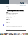
AT Interface Style
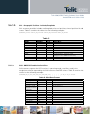
For information about AT Interface Backward Compatibility and #SELINT Factory
Setting for each type of Telit module covered by this guide refer to document [1]. For
reader convenience the Tab. 1 summarizes the Module Families in relation with the
supported AT Interface Style: 0, 1, 2. The switching among the supported AT Interface
Styles is performed with the #SELINT AT command.
AT Interface Style supported
Families & Modules
GM Family ( Modem)
GM862-QUAD
GM862-QUAD-PY
GM862-GPS
GC Family ( Compact )
GC864-QUAD
GC684-QUAD /w SIM holder
GC864-PY
GE Family ( Embedded )
GE863-QUAD
GE863-GPS
GE863-PY
GE863- SIM
3
GE863- PRO
3
GE863- PRO with Linux
GE864-QUAD
GE864-PY
GE864-AUTO
GE865-QUAD
GT Family ( Terminal )
GT863-PY
GT864-QUAD
GT864-PY
Factory Setting
0
0
0
1
1
1
2
2
2
0
0
0
1
1
1
2
2
2
0
0
0
0
0
0
-
1
1
1
1
1
1
-
2
2
2
2
2
2
2
2
2
2
0
0
0
1
1
1
2
2
2
Tab. 1: Modules and supported AT Interface Styles
Reproduction forbidden without Telit Communications S.p.A. written authorization - All Rights Reserved
page 13 of 154
Telit GSM/GPRS Family Software User Guide
1vv0300784 rev.3 2010-01-26
NOTE:
The AT commands described in this guide refer to the #SELINT 2 AT Interface Style.
2.2.
Turning ON the Module
Refer to [3].
2.3.
Turning OFF the Module
Refer to [3]
2.3.1. Software Shutdown
Issue the following command:
AT#SHDN
OK
During shutdown the module executes the following actions:
Detachment from the network
Module Power OFF
Reproduction forbidden without Telit Communications S.p.A. written authorization - All Rights Reserved
page 14 of 154
Telit GSM/GPRS Family Software User Guide
1vv0300784 rev.3 2010-01-26
2.4.
First Telit Module Approach
After a proper Power ON sequence the Telit module is ready to receive AT commands
on its Serial Port. Some functions have to be checked in order to be sure that the
module is ready to send and receive calls and SMS.
2.4.1. Telit Module Identification
Use the following AT command to verify if the connection between DTE and Telit
module (DCE) is working. The current serial port speed setting is Autobauding (Factory
Setting):
AT
OK
Use the following AT commands to verify the Software version and Telit module
identification:
AT+CGMR: Returns the Software version information
AT+CGMM: Returns the Telit Module identification
Examples
Checking the software version
AT+CGMR
07.02.604-A014
OK
Checking the module identification
AT+CGMM
GM862-QUAD
OK
2.4.2. Band Configuration
Use the following AT command to select the current band range:
AT#BND=[<band>];
The range of parameter <band> depends on the SELINT configuration, see [1] for
details.
Examples
AT#BND=[0]
Selected band: GSM 900MHz + DCS 1800MHz.
Reproduction forbidden without Telit Communications S.p.A. written authorization - All Rights Reserved
page 15 of 154
Telit GSM/GPRS Family Software User Guide
1vv0300784 rev.3 2010-01-26
Use the following AT command to enable/disable the automatic band selection at
power-on.:
AT#AUTOBND=[<value>];
The range of parameter <value> depends on the SELINT configuration, see [1] for
details.
The module is a quad band device, but in any case it is necessary to set the correct
working bands, see [1] for details.
2.4.3. Enabling the Extended Error Result codes
To enable the error report in numerical format for +Cxxx commands, issue the
following command:
AT+CMEE=1
OK
To enable the error report in verbose format for +Cxxx commands, issue the following
command:
AT+CMEE=2
OK
2.4.4. Serial Port Speed Configuration
Use the following AT command to specify the Serial Port speed of the Telit module
(DCE):
AT+IPR=<rate>
For a detailed description of parameters and possible responses, refer to [1].
Examples
Checking the current serial port speed setting (Factory Setting = autobauding):
AT+IPR?
+IPR: 0
OK
Checking the serial port speed range:
AT+IPR=?
+IPR:
(0,300,1200,2400,4800,9600,19200,38400,57600,115200),(0,300,1200
,2400,4800,9600,19200,38400,57600,115200)
OK
Setting up the serial port speed of the module (DCE) to 38400 bps:
Reproduction forbidden without Telit Communications S.p.A. written authorization - All Rights Reserved
page 16 of 154
Telit GSM/GPRS Family Software User Guide
1vv0300784 rev.3 2010-01-26
AT+IPR=38400
OK
Checking the current serial port speed:
NOTE:
Before entering the following AT command set up the DTE serial port to 38400 bps.
AT+IPR?
+IPR: 38400
OK
2.4.5. AT Command Interface selection
Use the following AT command to check the current AT Interface Style:
AT#SELINT?
For details on the possible responses, refer to [1].
Examples
After powering ON the module, checking the current AT Command Interface:
AT#SELINT?
#SELINT: 0
OK
Checking the AT Command Interfaces Set supported:
AT#SELINT=?
#SELINT: (0-2)
OK
Selecting an AT Command Interface Set:
AT#SELINT=2
OK
Select a wrong AT Command Interface Set just to see the response:
AT#SELINT=3
ERROR
Checking which AT Command Interface is active:
AT#SELINT?
#SELINT: 2
OK
Reproduction forbidden without Telit Communications S.p.A. written authorization - All Rights Reserved
page 17 of 154
Telit GSM/GPRS Family Software User Guide
1vv0300784 rev.3 2010-01-26
2.4.6. SIM Checking
2.4.6.1.
Query SIM presence and status
Issue the following command:
AT+CPIN?
Responses:
+CPIN: XXXX (Refer to [1] for the details.)
OK
ERROR
See table below:
Error results if extended error result codes is enabled, see +CMEE command
Numeric Format
+CME ERROR: XX
or Verbose Format
Details
understandable message
Refer to [1]
Examples
The SIM is not inserted into Telit Module. Extended error result code is not enabled.
Checking if PIN code is needed, just to see the response command:
AT+CPIN?
ERROR
The SIM is not inserted into Telit Module. Verbose extended error result code is
enabled. Checking if PIN code is needed, just to see the response command:
AT+CPIN?
+CME ERROR: SIM not inserted
The SIM is not inserted into Telit Module. Numerical extended error result code is
enabled. Checking if PIN code is needed, just to see the response command:
AT+CPIN?
+CME ERROR: 10
Inserting the SIM into Telit Module and checking if PIN code is needed:
AT+CPIN?
+CPIN: SIM PIN
OK
Reproduction forbidden without Telit Communications S.p.A. written authorization - All Rights Reserved
page 18 of 154
Telit GSM/GPRS Family Software User Guide
1vv0300784 rev.3 2010-01-26
2.4.6.2. SIM PIN
Issue the following command:
AT+CPIN=<pin>
For parameter description refer to [1].
Responses:
OK
ERROR
See table below:
Error results if extended error result codes is enabled, see +CMEE command
Numeric Format
or Verbose Format
Details
+CME ERROR: XX
understandable message
Refer to [1]
Examples
A wrong PIN code is entered. Extended error result is not enabled.
AT+CPIN=1235
ERROR
A right PIN code is entered:
AT+CPIN=1234
OK
A wrong PIN code is entered. Verbose extended error result code is enabled:
1. Enabling Verbose extended error result code:
AT+CMEE=2
OK
2. Entering a wrong PIN code:
AT+CPIN=1235
+CME ERROR: incorrect password.
NOTE:
After 3 failed attempts SIM PIN is no longer requested and the SIM is locked. Use SIM
PUK to enter a new SIM PIN and unlock the SIM.
Reproduction forbidden without Telit Communications S.p.A. written authorization - All Rights Reserved
page 19 of 154
Telit GSM/GPRS Family Software User Guide
1vv0300784 rev.3 2010-01-26
2.4.6.3. SIM PUK
Issue the following command:
AT+CPIN=<pin>[,<newpin>]
For parameter description refer to [1].
Responses:
OK
ERROR
See table below:
Error results if extended error result codes is enabled, see +CMEE command
Numeric Format
+CME ERROR: XX
or Verbose Format
Details
understandable message
Refer to [1]
TIP:
After 10 failed attempts to enter SIM PUK code, the SIM Card is locked and no longer
available.
2.4.6.4. Preferred Operator List
Use the following AT command to manage the Preferred Operator List stored on SIM.
AT+CPOL=[<index>][,<format>[,<oper>]]
For parameter description refer to [1].
Responses:
+CPOL: ……… (Refer to [1] for the details.)
OK
ERROR
See table below:
Error results if extended error result codes is enabled, see +CMEE command
Numeric Format
+CME ERROR: XX
or Verbose Format
Details
understandable message
Refer to [1]
Reproduction forbidden without Telit Communications S.p.A. written authorization - All Rights Reserved
page 20 of 154
Telit GSM/GPRS Family Software User Guide
1vv0300784 rev.3 2010-01-26
Examples
Checking the supported parameters:
AT+CPOL=?
+CPOL: (1-20),(2)
OK
NOTE:
The used SIM supports 20 positions. The supported format (2) is numeric.
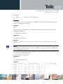
Reading the entire list:
AT+CPOL?
+CPOL: 1,2,"20801"
+CPOL: 2,2,"20810"
+CPOL: 3,2,"23205"
+CPOL: 4,2,"22802"
+CPOL: 5,2,"29341"
+CPOL: 6,2,"26207"
+CPOL: 7,2,"21403"
+CPOL: 8,2,"21910"
+CPOL: 9,2,"21601"
+CPOL: 10,2,"23410"
+CPOL: 11,2,"20201"
+CPOL: 12,2,"20408"
+CPOL: 13,2,"26003"
+CPOL: 14,2,"20610"
+CPOL: 15,2,"23002"
+CPOL: 16,2,"26803"
+CPOL: 17,2,"27202"
+CPOL: 18,2,"24001"
+CPOL: 19,2,"23802"
+CPOL: 20,2,"24201"
OK
Reproduction forbidden without Telit Communications S.p.A. written authorization - All Rights Reserved
page 21 of 154
Telit GSM/GPRS Family Software User Guide
1vv0300784 rev.3 2010-01-26
NOTE:
The meaning of the string “XXXYY” is the following:
- XXX = Mobile Country Code
- YY = Mobile Network Code
Trying to delete the first entry using a non-existent <format> value just to see the
response when the Extended Error Result code is enabled:
AT+CPOL=1,3
+CME ERROR: operation not supported
Deleting the first entry using a right <format> value:
AT+CPOL=1,2
OK
Checking if the first entry is deleted:
AT+CPOL?
+CPOL: 2,2,"20810"
+CPOL: 3,2,"23205"
.
.
+CPOL: 19,2,"23802"
+CPOL: 20,2,"24201"
OK
NOTE:
The entry on first position is deleted.
Writing a new entry on first position:
AT+CPOL=1,2,20801
OK
Checking if the first entry is written on first position:
AT+CPOL?
+CPOL: 1,2,"20801"
+CPOL: 2,2,"20810"
.
.
Reproduction forbidden without Telit Communications S.p.A. written authorization - All Rights Reserved
page 22 of 154
Telit GSM/GPRS Family Software User Guide
1vv0300784 rev.3 2010-01-26
+CPOL: 19,2,"23802"
+CPOL: 20,2,"24201"
OK
NOTE:
The new entry is written on first position.
2.4.7. Network checking
2.4.7.1. Query Network status
Issue the following command:
AT+CREG?
Responses:
+CREG: X,Y (Refer to [1] for the details.)
OK
ERROR
See table below:
Error results if extended error result codes is enabled, see +CMEE command
Numeric Format
+CME ERROR: XX
or Verbose Format
Details
understandable message
Refer to [1]
Examples:
Checking if Telit Module is registered:
AT+CREG?
+CREG: 0,1
OK
The antenna is not connected to the Telit Module, repeating the previous AT command:
AT+CREG?
+CREG: 0,3
OK
Telit Module is registered. Collecting Local Area Code and Cell Id:
AT+CREG=2
OK
Reproduction forbidden without Telit Communications S.p.A. written authorization - All Rights Reserved
page 23 of 154
Telit GSM/GPRS Family Software User Guide
1vv0300784 rev.3 2010-01-26
AT+CREG?
+CREG: 2,1,55FA,12EB
OK
A wrong parameter is entered just to see the result format when verbose extended
error result is enabled:
AT+CREG=9
+CME ERROR: operation not supported
2.4.7.2. Network Operator Identification
Once the mobile has registered on some Network, it is possible to query the mobile for
Network identifications codes and names with the following command:
AT+COPS=?
Responses:
OK
+COPS: (……) (Refer to [1] for the details.)
ERROR
See table below:
Error results if extended error result codes is enabled, see +CMEE command
Numeric Format
+CME ERROR: XX
or Verbose Format
Details
understandable message
Refer to [1]
Examples
Telit Module is registered. Collecting Networks Operators Identifications:
AT+COPS=?
+COPS: (2,"I WIND",,"22288"),(3,"vodafone
IT",,"22210"),(1,"SI.MOBIL",,"29340"),,(0-4),(0,2)
OK
The antenna is not connected to the Telit Module. Verbose extended error result is
enabled. Repeating the previous AT command:
AT+COPS=?
+CME ERROR: no network service
2.4.7.3. Received Signal Strength & Quality
Once the mobile has registered on a Network, it may be useful to know the received
signal strength & quality to give the User an indication about the radio link reliability.
Use the following AT command:
AT+CSQ
Reproduction forbidden without Telit Communications S.p.A. written authorization - All Rights Reserved
page 24 of 154
Telit GSM/GPRS Family Software User Guide
1vv0300784 rev.3 2010-01-26
Responses:
OK
+CSQ: XX,YY (Refer to [1] for the details.)
ERROR
See table below:
Error results if extended error result codes is enabled, see +CMEE command
Numeric Format
+CME ERROR: XX
or Verbose Format
Details
understandable message
Refer to [1]
Examples
The antenna is not connected to the Telit Module.
AT+CSQ
+CSQ: 99,99
OK
The antenna is connected to the Telit Module. Repeating the previous AT command:
AT+CSQ
+CSQ: 17,0
OK
NOTE:
<rssi> = Received Signal Strength Ind. = 17, <ber> = Bit Error Rate = 0.
A wrong parameter is entered just to see the result format when verbose extended
error result is enabled:
AT+CSQ?
+CME ERROR: operation not supported
NOTE:
When Received Signal Strength Indication is less than 6 the radio link quality is poor,
the call could be cut off.
NOTE:
The quality is measured on the traffic channel, hence it is available only during a
conversation, in Idle the reported value must not be considered.
In conversation the quality decreases with the increase of the <ber> number.
Reproduction forbidden without Telit Communications S.p.A. written authorization - All Rights Reserved
page 25 of 154
Telit GSM/GPRS Family Software User Guide
1vv0300784 rev.3 2010-01-26
NOTE:
The <ber> value refers strictly to the GSM radio channel and is a very technical
parameter, it can be used to monitor the voice call quality since the voice quality is
inversely proportional to the <ber> number.
NOTE:
The reported signal quality only refers to the GSM radio channel link and not to the
whole path from the caller to the receiver. It may happen that the quality on the GSM
radio link is very good and hence the reported <ber> is 0 (good quality) but the quality of
the remaining path to the other party is very bad and hence the final data connection
quality is very poor. For this reason the signal quality indicator <ber> should not be
taken into account to monitor data calls quality.
2.4.7.4. Network Status Checking
Once the Telit Module is registered on a Network, it could be useful to know the
received signal strength and the Network on which the Telit Module is registered. This
information can be gathered by means of the following standard AT commands: +CREG,
+COPS and +CSQ. These commands are not fast in the response due to Network
response time, especially the +COPS command; if the User objective is to keep the
Software Application as general as possible, he/she can use the standard AT
commands above mentioned and described on the previous paragraphs.
Telit Modules provide the User with proprietary AT commands to gather all the
information needed in a faster and simpler way. The proprietary AT commands are:
#MONI, #SERVINFO.
Selecting the Serving Cell
Select the Serving Cell with the following set command:
AT#MONI=0
Responses:
OK
ERROR
Collecting the Serving Cell Information
Collect the Serving Cell Information with the following execution command:
AT#MONI
Reproduction forbidden without Telit Communications S.p.A. written authorization - All Rights Reserved
page 26 of 154
Telit GSM/GPRS Family Software User Guide
1vv0300784 rev.3 2010-01-26
Response:
#MONI: …………… (Refer to [1] for the details.)
OK
Examples
The antenna is not connected to the Telit Module. Trying to collect Cells Information
just to see the format response:
AT#MONI
ERROR
OK
The antenna is connected to the Telit Module. Collecting network information only
about the serving cell.
1. Selecting Serving Cell:
AT#MONI=0
OK
2.Collecting information:
AT#MONI
#MONI: I WIND BSIC:70 RxQual:0 LAC:55FA Id:12EB ARFCN:979 PWR:75dbm TA:0
OK
NOTE:
The module is registered on the network "I WIND", the signal strength is -75dBm. For
more information, refer to [1].
The antenna is connected to the Telit Module. Collecting network information about the
serving cell and neighboring cells.
1. Selecting all available cells:
AT#MONI=7
OK
2. Collecting information:
AT#MONI
#MONI:
Cell BSIC
LAC
CellId ARFCN Power
C1
C2
TA
RxQual
PLMN
#MONI:
S
70
55FA
12EB
979
-75 dbm
29
29
0
0
I WIND
#MONI:
N1
75
55FA
1297
983
-86 dbm
18
18
#MONI:
N2
70
55FA
12EA
985
-87 dbm
17
17
#MONI:
N3
73
55FA
1D23
754
-100 dbm
2
16
#MONI:
N4
72
55FA
12EC
977
-101 dbm
3
3
#MONI:
N5
72
55FA
1D0D
751
-107 dbm
-5
-5
Reproduction forbidden without Telit Communications S.p.A. written authorization - All Rights Reserved
page 27 of 154
Telit GSM/GPRS Family Software User Guide
1vv0300784 rev.3 2010-01-26
#MONI:
N6
FF
FFFF
0000
1007
-107 dbm
-1
-1
OK
NOTE:
The module is registered on the network "I WIND", the signal strength is -75dBm. For
more information, refer to [1].
Collecting the Serving Cell Information
Collect the Serving Cell Information with the following execution command:
AT#SERVINFO
Response:
o
OK
#SERVINFO: …………… (Refer to [1] for the details.)
Examples
The Telit Module is registered. Collecting network information only about the serving
cell:
AT#SERVINFO
#SERVINFO: 979,-75,"I WIND","22288",70,55FA,00,1,,"II",01,6
OK
NOTE:
The module is registered on the network "I WIND", the signal strength is -75dBm. For
more information, refer to [1].
NOTE:
This command should be used only to gather information about network name and
signal strength. To check if mobile is registered or is looking for a suitable network to
register on, use +CREG command. As a matter of fact, if the network signal is too weak
and mobile looses the registration, until a new network is found the #MONI command
reports the last measured valid values and not the real ones. The TA (timing advance
parameter) is valid only during a call.
TIP:
Check network registration with +CREG command, see § 0. When mobile is registered
query the mobile for network operator name and signal strength with #MONI command.
Reproduction forbidden without Telit Communications S.p.A. written authorization - All Rights Reserved
page 28 of 154
Telit GSM/GPRS Family Software User Guide
1vv0300784 rev.3 2010-01-26
2.4.7.5.
Enhanced Network Selection and AT&T functions
Use the following set command to enable/disable the Enhanced Network Selection and
the AT&T functions. The Telit module features enabled or disabled by this command
are conditioned by the SIM card type used, as pointed out by the following notes.
AT#ENS=[<mode>]
For parameter description, refer to [1].
Responses:
OK
ERROR
Examples
Scenario 1: module with any SIM card.
AT#ENS=0
OK
NOTE: After entering the command, power OFF/ON the module to make the selected
operation active. The module follows the Standard European operation described by the
3GPP specification R98, (factory configuration).
Scenario 2: module with no AT&T SIM cards.
AT#ENS=1
OK
NOTE: After entering the command, power OFF/ON the module to make the selected
operation active. The module follows the Standard European operation described by the
3GPP specification R98 and supports the following features:
use of EONS features (refer to [9], § 15)
use of the ENS features for Network selection (refer to [9], §13)
support of special requirements for USSD strings (refer to [9], <CDR-GSM-255>
special support of strings ATDxxxxxPyyyyyy (refer to [9] <CDR-CON-3074>,
<CDR-CON-3342>)
AT#AUTOBND=1 as default, if previous value ≠ 2
AT#BND supports only values 0 and 3
support of AT command PACSP to display the PLMNModeBit (refer to [9])
AT#STIA=2,10 as default
use of the max telephone number written on SIM instead of a default value
equal to 20
Reproduction forbidden without Telit Communications S.p.A. written authorization - All Rights Reserved
page 29 of 154
Telit GSM/GPRS Family Software User Guide
1vv0300784 rev.3 2010-01-26
tone on USSD reception (refer to [9])
AT#PLMNMODE=1 as default
different coding and encoding for MCC and MNC for SAT functions (refer to [9])
BA list saving on the module (refer to [9], <CDR-NWS-140>)
special handling of store field into the MWI messages (refer to [9], §16)
Scenario 3: module with an AT&T SIM card.
NOTE:
The following setting is recommended for AT&T SIM card.
AT#ENS=1
OK
NOTE:
After entering the command, power OFF/ON the module to make the selected
operation active. The module follows the Standard European operation described by the
3GPP specification R98 and supports the features indicated in scenario 2, plus the
following:
- use of the Acting Home PLMN feature (refer to [9], § 12)
- the module writes in the SIM card the Location Info. using the AT&T coding
NOTE:
when AT#ENS=1, it is recommended to use the following setting:
AT#AUTOBND=2
AT#NITZ=7,X (X if the user wants the URC)
AT#SMSMODE=1
Reproduction forbidden without Telit Communications S.p.A. written authorization - All Rights Reserved
page 30 of 154
Telit GSM/GPRS Family Software User Guide
1vv0300784 rev.3 2010-01-26
2.5.
Establishing a Voice call
1
Before setting up a Voice Call, it is recommended to check if the Telit Module is
registered on a network (see § 0) and if the signal strength is enough to carry on the
radio link.
2.5.1.
Setting up a Voice Call
This section describes how to set up a voice call.
2.5.1.1.
Setting the Module in Voice Mode
Use the following AT command to set up the module for a Voice Call:
AT+FCLASS=8
OK
NOTE:
+FCLASS=8 command may be omitted if the ";" modifier is added at the end of the ATD
command, after the number to be dialed, see §2.5.2.
2.5.1.2.
Setting the Desired Audio Path Active
The present section is applicable to the Telit Modules supporting the connection of
2
audio devices , refer to [2], [3].
Telit Modules have two different audio paths:
internal microphone/ear (MT)
external microphone/ear (HF)
Usually the internal path is used for a handset function, while the external is used for
hands-free function. There are two ways to switch between these two paths:
SOFTWARE and HARDWARE, see the following AT command examples:
AT#CAP=<n>
OK
For parameter description refer to [1].
1
Audio connection is not supported by GT863-PY and GT864-PY
Reproduction forbidden without Telit Communications S.p.A. written authorization - All Rights Reserved
page 31 of 154
Telit GSM/GPRS Family Software User Guide
1vv0300784 rev.3 2010-01-26
Examples
Using SOFTWARE way to select internal audio path (MT):
AT#CAP=2
OK
Using SOFTWARE way to select external audio path (HF):
AT#CAP=1
OK
Using HARDWARE way to select audio path:
AT#CAP=0
OK
Selecting the audio path by means of the pin AXE [3]:
set the hardware pin AXE = HIGH to select internal audio path (MT).
set the hardware pin AXE = LOW to select external audio path (HF).
TIP:
When HARDWARE control is not used AXE pin can be left unconnected.
TIP:
The audio paths can be switched also during a call in both ways.
Reproduction forbidden without Telit Communications S.p.A. written authorization - All Rights Reserved
page 32 of 154
Telit GSM/GPRS Family Software User Guide
1vv0300784 rev.3 2010-01-26
2.5.1.3.
Setting the Desired Volume on the Active Audio Path Speaker Output
Use the following AT command to set up the volume level:
AT+CLVL=<vol>
OK
For parameter description refer to [1].
NOTE:
The volume setting refers to the ACTIVE path ear line and is stored each time. When
changing audio path the volume setting will be reset to the previously stored value for
that audio path.
2.5.1.4.
Checking for Microphone Mute Setting
The microphone of the active path can be muted with AT+CMUT=1 command; to be
sure that it is not muted use the following read command:
AT+CMUT?
Response:
+CMUT: X (Refer to [1] for the details.)
OK
NOTE:
The mute setting does not work the same way as the volume setting. The mute setting
configuration is valid for both audio paths.
Reproduction forbidden without Telit Communications S.p.A. written authorization - All Rights Reserved
page 33 of 154
Telit GSM/GPRS Family Software User Guide
1vv0300784 rev.3 2010-01-26
2.5.2.
Dialing a Phone Number (Voice Call)
AT command used to dial up a phone number.
ATD <number>[;]
For parameter and response description refer to [1].
Examples
Calling the national number 040-4X92XYX. The module is set in voice mode
(AT+FCLASS=8 has been executed).
ATD 0404X92XYX
OK
Calling the national number 040-4X92XYX in international format +39-040-4X92XYX. The
module is set in voice mode (AT+FCLASS=8 has been executed).
ATD +390404X92XYX
OK
Calling the national number 040-4X92XYX in international format +39-040-4X92XYX. The
module is not set in voice mode (AT+FCLASS=8 has not been executed). In this case to
perform the Voice Call the User must use the “;” character at the end of the command.
ATD +390404X92XYX;
OK
2.5.3.
Closing the Voice Call
Use the following AT command to close the current Voice Call:
ATH
OK
TIP:
During the voice call the module is in command mode, so the escape sequence (+++)
must not be issued before sending commands.
Reproduction forbidden without Telit Communications S.p.A. written authorization - All Rights Reserved
page 34 of 154
Telit GSM/GPRS Family Software User Guide
1vv0300784 rev.3 2010-01-26
2.6.
Establishing a CSD Data Call
Before establishing a CSD Data Call (not GPRS), it is recommended to check if the Telit
module is registered on a Network and if the signal is strong enough to support the
radio link (see § 0).
2.6.1.
Setting up Data Call Device
This section describes how to set up the data call device.
2.6.1.1.
Setting the Device in Data Mode
Use the following AT command to set up the module for a Data Call:
AT+FCLASS=0
OK
TIP:
The +FCLASS setting is stored in memory, so there is no need to repeat this command
if +FCLASS setting is not required to change.
2.6.1.2.
Setting the Desired Modulation and Speed for the Connection
The Data Connection can be established using different speeds, bearer services,
connection element. The connection mode can be selected with the following set
command:
AT+CBST[=<speed>[,<name>[,<ce>]]]
OK
For parameter description refer to [1].
Examples
Reading current values:
AT+CBST?
+CBST: 0,0,1
OK
Setting new speed:
AT+CBST=1,0,1
OK
Reproduction forbidden without Telit Communications S.p.A. written authorization - All Rights Reserved
page 35 of 154
Telit GSM/GPRS Family Software User Guide
1vv0300784 rev.3 2010-01-26
Checking if new speed value is set:
AT+CBST?
+CBST: 1,0,1
OK
TIP:
It is recommended to use the Non Transparent connection to avoid the reception of
characters not concerning the transmitted message.
2.6.2.
Dialing a Phone Number (Data Call)
Use the following command to dial a phone number:
ATD <number>
For parameter and response description refer to [1].
Examples
Calling the national number 040-4X92XYX. The module is set in data mode
(AT+FCLASS=0 has been executed).
ATD 0404X92XYX
CONNECT 9600
Calling the national number 040-4X92XYX in international format +39-40-4X92XYX. The
module is set in data mode (AT+FCLASS=0 has been executed).
ATD +39404X92XYX
CONNECT 9600
TIP:
The response to the ATD command is returned after the modem handshaking, this
takes about 30 seconds, so allow this time before doing anything.
TIP:
When the module is doing the handshake to establish the connection, entering any
character closes the handshake and aborts the call.
Reproduction forbidden without Telit Communications S.p.A. written authorization - All Rights Reserved
page 36 of 154
Telit GSM/GPRS Family Software User Guide
1vv0300784 rev.3 2010-01-26
2.6.3.
Closing the Data Call
This section describes how to close a data call.
2.6.3.1.
Exiting the Data Mode and Entering the Command Mode
To exit the module Data Mode, do the following:
1. Enter the following Escape Sequence: +++
2. Wait for the escape sequence pause time (see S12 parameter, refer to [1]).
3. Wait for the response OK.
NOTE:
After the Escape Sequence and during the call the only command accepted by the
module is the ATH . All the other commands are not supported during a call.
TIP:
In order to enter the Command Mode no characters must be sent between two
consecutive “+” characters (escape sequence pause time S12) forming the Escape
Sequence.
2.6.3.2.
Hanging up the Data Call
Use the following AT command to close the current data connection:
ATH
NO CARRIER
TIP:
During the data call the module is in data mode (on line), so the escape sequence (+++)
must be issued before sending AT commands to the module.
Reproduction forbidden without Telit Communications S.p.A. written authorization - All Rights Reserved
page 37 of 154
Telit GSM/GPRS Family Software User Guide
1vv0300784 rev.3 2010-01-26
Answering an Incoming Call 3
2.7.
When an Incoming Call is detected, the module reports an Unsolicited Code. For details,
refer to [1].
To answer the call, use the following AT command:
ATA
For response details, refer to [1].
TIP:
The call is answered with the appropriate type (VOICE or DATA) regardless of the
+FCLASS setting active. To distinguish between Data and Voice see the command
response or the extended format incoming call indication.
3
In GT863-PY and GT864-PY modules the audio hardware in not supported.
Reproduction forbidden without Telit Communications S.p.A. written authorization - All Rights Reserved
page 38 of 154
Telit GSM/GPRS Family Software User Guide
1vv0300784 rev.3 2010-01-26
2.8.
Enabling TTY Function
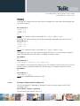
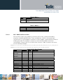
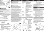
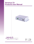
The characters entered through the TTY device, connected to the Telit module (see fig.
1), are coded using the following two tones: 1400 Hz and 1800 Hz. These tones are not
supported by the GSM speech coder, consequently they must be transformed to be
compatible with the speech coder. This activity is performed by the CTM modem that in
the Telit module solution is internal to the module itself. The internal CTM modem
transforms the two unsupported tones into the following four tones: 400Hz, 600Hz,
800Hz, 1000Hz that can be managed by the speech coder. The TTY device can be
connected to the Telit module using one of the two audio paths provided by the module
itself. This feature enables the transmission of the TTY data and voice jointly on the
existing speech channel of the module.
Generic solution
Telit module
TTY device
1400/1800
CTM
modem
GSM
engine
GSM
network
GSM
engine
CTM
modem
TTY
device
fig. 1: TTY device – module connection
Examples
Connect the TTY device (1400/1800) to the selected analog audio line of the module. In
accordance with the selected physical audio connection, configure the audio path as
indicated below.
Selecting the Hands Free audio path (“HF lines”, refer to § 2.5.1.2; Audio 2, refer to [6]):
1.
Using SOFTWARE way to select external audio path (HF):
AT#CAP=1
OK
2.
Setting the volume of the active audio path:
AT+CLVL=5
OK
3.
Setting the Hands Free microphone input gain:
AT#HFMICG=4
OK
4.
Disabling the side tone on Hands Free audio output:
Reproduction forbidden without Telit Communications S.p.A. written authorization - All Rights Reserved
page 39 of 154
Telit GSM/GPRS Family Software User Guide
1vv0300784 rev.3 2010-01-26
AT#SHFSD=0
OK
5.
Disabling echo canceller function on Hands Free audio output:
AT#SHFEC=0
OK
6.
Disabling automatic gain control for Hands Free mode:
AT#SHFAGC=0
OK
7.
Disabling noise reduction for Hands Free mode:
AT#SHFNR=0
OK
8.
Enable the transmission of data on the existing speech channels:
AT#TTY=1
OK
After this configuration, the next Voice Call will be able to jointly support voice and TTY
data.
Using the Hand Set audio path (“MT lines”, refer to § 2.5.1.2; Audio 1, refer to [6]):
1.
Using SOFTWARE way to select internal audio path (HS):
AT#CAP=2
OK
2.
Setting the volume of the active audio path:
AT+CLVL=5
OK
3.
Setting the Hand Set microphone input gain:
AT#HSMICG=4
OK
4.
Disabling the side tone on Hand Set audio output:
AT#SHSSD=0
OK
5.
Disabling echo canceller function on Hand Set audio output:
AT#SHSEC=0
OK
6.
Disabling automatic gain control for Hand Set mode:
AT#SHSAGC=0
OK
Reproduction forbidden without Telit Communications S.p.A. written authorization - All Rights Reserved
page 40 of 154
Telit GSM/GPRS Family Software User Guide
1vv0300784 rev.3 2010-01-26
7.
Disabling noise reduction for Hand Set mode:
AT#SHSNR=0
OK
8.
Enabling the transmission of data on the existing speech channels:
AT#TTY=1
OK
After this configuration, the next Voice Call will be able to jointly support voice and TTY
data.
Reproduction forbidden without Telit Communications S.p.A. written authorization - All Rights Reserved
page 41 of 154
Telit GSM/GPRS Family Software User Guide
1vv0300784 rev.3 2010-01-26
3.
Advanced Operations
3.1.
Accessing the Phonebook
The User can access the phonebook storage of the SIM card inserted on Telit module.
By means of dedicated AT commands the User stores and recalls phone numbers and
their associated names.
The Telit module supports the following SIM phonebook storages:
"SM" - SIM phonebook
This is the PB used to store and recall numbers during the normal operation of the
module.
"FD" - SIM fixed dialing-phonebook (only phase 2/2+ SIM)
This PB has several restrictions; to set it you need the PIN2 code and after having
activated the FD only the calls to the numbers stored in the FD or their children are
allowed, all the other calls are forbidden.
"LD" - SIM last-dialing-list (+CPBW and +CPBF are not applicable for this storage)
This is the list of the last dialed numbers, it is updated automatically at each call
originated and insertion or search on it is not possible, the only operations allowed
are recall, read and delete.
"MC" - SIM missed-calls-list (+CPBW and +CPBF are not applicable for this
storage)
This is the list of the missed calls calling numbers, it is updated automatically at
each call missed and insertion or search on it is not possible, the only operations
allowed are recall, read and delete.
"RC" - SIM received-calls-list (+CPBW and +CPBF are not applicable for this
storage)
This is the list of the received calls calling numbers, it is updated automatically at
each call received and insertion or search on it is not possible, the only operations
allowed are recall, read and delete.
In order to access the storage the User has to choose one. This must be the first Phone
Book operation always. Once storage is selected, it is no longer needed to select it
again until the desired storage remains the same and the module is turned off.
3.1.1.
Selecting Phonebook Memory Storage
Use the following AT command to select the phonebook memory storage:
AT+CPBS=<storage>
For parameter description refer to [1].
Reproduction forbidden without Telit Communications S.p.A. written authorization - All Rights Reserved
page 42 of 154
Telit GSM/GPRS Family Software User Guide
1vv0300784 rev.3 2010-01-26
Responses:
OK
ERROR
See the table below:
Error results if extended error result codes is enabled, see +CMEE command
Numeric Format
or Verbose Format
Details
+CME ERROR: XX
understandable message
Refer to [1]
Examples
Reading the supported range of phonebook storages:
AT+CPBS=?
+CPBS: ("SM","FD","LD","MC","RC")
OK
Reading the actual phonebook storage:
AT+CPBS?
+CPBS: "SM",10,250
OK
Selecting “FD” phonebook storage:
AT+CPBS="FD"
ERROR
AT+CMEE=2
OK
AT+CPBS="FD"
+CME ERROR: SIM PIN2 required
NOTE:
When the FD storage is selected, the PIN2 must be inserted or the FD facility must be
enabled. To enable the facility use +CLCK command (see par. 3.1.1.1)
NOTE:
If PIN2 is used, after 3 failed attempts the SIM is blocked. To unblock the SIM use PUK2,
refer to § 2.4.6.
Reproduction forbidden without Telit Communications S.p.A. written authorization - All Rights Reserved
page 43 of 154
Telit GSM/GPRS Family Software User Guide
1vv0300784 rev.3 2010-01-26
Selecting “MC” phonebook storage:
AT+CPBS="MC"
OK
AT+CPBS?
+CPBS: "MC",0,20
OK
NOTE:
After powering up and PIN authentication, the module reads the data records stored on
the SIM for a backup. During this activity the SIM access is inhibited (SIM is busy after
the issue of the PIN or after powering up if PIN request is disabled) for a time varying
from few seconds to about one minute, depending on the percentage of written records
in the SIM phonebook. If Phonebook commands are issued during this time interval the
module returns an error message. If this happens, retry the operations later.
3.1.1.1.
Locking or Unlocking ME
4
Use the following AT command to lock or unlock an ME or a Network facility:
AT+CLCK=<fac>,<mode>[,<passwd>[,<class>]]
For parameter description refer to [1].
Responses:
OK
ERROR
See table below:
Error results if extended error result codes is enabled, see +CMEE command
Numeric Format
+CME ERROR: XX
or Verbose Format
Details
understandable message
Refer to [1]
Examples
Reading the supported facilities:
AT+CLCK=?
+CLCK: ("SC","FD","AO","OI","OX","AI","IR","AB","AG","AC","PN","
PU","PP","PC","PS","PF")
OK
4
ME = module
Reproduction forbidden without Telit Communications S.p.A. written authorization - All Rights Reserved
page 44 of 154
Telit GSM/GPRS Family Software User Guide
1vv0300784 rev.3 2010-01-26
Querying the status of the facility “SC”:
AT+CLCK="SC",2
+CLCK: 1
OK
Querying the status of a wrong facility just to see the format response. Before doing
that verify the Extended error result code.
AT+CMEE?
+CMEE: 2
OK
AT+CLCK="S1",2
+CME ERROR: operation not supported
3.1.2.
Finding Phonebook Entries
Use the following AT command to find a phonebook entry.
AT+CPBF=<findtext>
For parameter description refer to [1].
Responses:
+CPBF: ……… (Refer to [1] for the details.)
OK
ERROR
See table below:
Error results if extended error result codes is enabled, see +CMEE command
Numeric Format
+CME ERROR: XX
or Verbose Format
Details
understandable message
Refer to [1]
NOTE:
The search for <name> string is not case sensitive and the string may or may not be
included in double brackets.
Examples
Reading the actual phonebook storage and selecting “SM” storage:
AT+CPBS?
+CPBS: "MC",0,20
OK
Reproduction forbidden without Telit Communications S.p.A. written authorization - All Rights Reserved
page 45 of 154
Telit GSM/GPRS Family Software User Guide
1vv0300784 rev.3 2010-01-26
AT+CPBS="SM"
OK
AT+CPBS?
+CPBS: "SM",10,250
OK
Looking for entries having name starting with: "FA" on the selected storage:
AT+CPBF="FA"
+CPBF: 7,"+39404192369",145,"Fabio"
+CPBF: 9,"0404X92XYX",129,"Fabrizio"
OK
Looking for an entry not present on the selected storage. Before doing that verify if the
Extended Error Result Code is enabled.
AT+CMEE?
+CMEE: 2
OK
AT+CPBF="FAUSTO"
+CME ERROR: not found
3.1.3.
Reading Phonebook Entries
Use the following AT command to read a phonebook entry:
AT+CPBR=<index1>[,<index2>]
For parameter description refer to [1].
Responses:
+CPBR: ……… (Refer to [1] for the details.)
OK
ERROR
See table below:
Error results if extended error result codes is enabled, see +CMEE command
Numeric Format
+CME ERROR: XX
or Verbose Format
understandable message
Details
Refer to [1]
Examples
Selecting “SM” storage:
AT+CPBS="SM"
OK
Reproduction forbidden without Telit Communications S.p.A. written authorization - All Rights Reserved
page 46 of 154
Telit GSM/GPRS Family Software User Guide
1vv0300784 rev.3 2010-01-26
Looking for the entry at the position index = 7:
AT+CPBR=7
+CPBR: 7,"+39404192369",145,"Fabio"
OK
Looking for the entries at the positions from 7 up to 9 and for example the position at
index 8 is empty:
AT+CPBR=7,9
+CPBR: 7,"+39404192369",145,"Fabio"
+CPBR: 9,"0404X92XYX",129,"Fabrizio"
OK
3.1.4.
Writing a Phonebook Entry
First, the User must select the desired storage as active, then use the following AT
command to write a phonebook entry:
AT+CPBW=[<index>][,<number>[,<type>[,<text>]]]
For parameters description refer to [1].
Responses:
+CPBW: ……… (Refer to [1] for details.)
OK
ERROR
See table below:
Error results if extended error result codes is enabled, see +CMEE command
Numeric Format
+CME ERROR: XX
or Verbose Format
Details
understandable message
Refer to [1]
Examples
Selecting the "SM" phonebook:
AT+CPBS="SM"
OK
Writing a new record on the "SM" phonebook:
AT+CPBW=,"0404192123",129,"NewRecord"
OK
Checking where the new record has been written:
Reproduction forbidden without Telit Communications S.p.A. written authorization - All Rights Reserved
page 47 of 154
Telit GSM/GPRS Family Software User Guide
1vv0300784 rev.3 2010-01-26
AT+CPBF="NEW"
+CPBF: 8,"0404192123",129,"NewRecord"
OK
3.1.5.
Deleting a Phonebook Entry
First, the User must select the desired storage as active, then use the following AT
command to delete a phonebook entry:
AT+CPBW=<index>
For parameter description refer to [1].
Responses:
+CPBW: ……… (Refer to [1] for details.)
OK
ERROR
See table below:
Error results if extended error result codes is enabled, see +CMEE command
Numeric Format
+CME ERROR: XX
or Verbose Format
Details
understandable message
Refer to [1]
Examples
Selecting the "SM" phonebook:
AT+CPBS="SM"
OK
Deleting a record on the "SM" phonebook:
AT+CPBW= 7
OK
Deleting an non-existent record on the "SM" phonebook, just to see the format
response:
AT+CPBF=99999999999
+CME ERROR: not found
TIP:
The delete operation simply overwrites the record number <index> with an empty
record.
Reproduction forbidden without Telit Communications S.p.A. written authorization - All Rights Reserved
page 48 of 154
Telit GSM/GPRS Family Software User Guide
1vv0300784 rev.3 2010-01-26
If the record to be deleted was already empty, no error messages will be shown, but it
will be only filled again with empty values.
3.1.6.
Dialing a Phonebook Entry
To dial a number previously stored in the phonebook, first the User must get the
desired phone number index position using the +CPBF command. Once the <index>
number is known, the User must set up the module for the needed type of call.
ATD> <n>[;]
For parameter description refer to [1].
Wait for the response according to the call type issued.
Examples
Establishing a Voice call on the internal audio path MT to "Fabio" whose number is
stored on the SIM phonebook:
1.
Select the “SM” phone book as active storage.
AT+CPBS="SM"
OK
2.
Find the index number where "Fabio" is recorded.
AT+CPBF="Fabio"
+CPBF: 7,"+390404X9YYYY",145,"Fabio"
OK
NOTE: The first field is the index position: 7.
3.
Set up Voice Call.
AT+FCLASS=8
OK
4.
Use SOFTWARE way to select internal audio path (MT).
AT#CAP=2
OK
5.
Set the volume.
AT+CLVL=8
OK
6.
Check the mute setting.
AT+CMUT?
+CMUT: 0
Reproduction forbidden without Telit Communications S.p.A. written authorization - All Rights Reserved
page 49 of 154
Telit GSM/GPRS Family Software User Guide
1vv0300784 rev.3 2010-01-26
7.
Establish the voice call using the index, see the previous command:
AT+CPBF="Fabio".
ATD> 7
OK
3.2.
Call Management
3.2.1.
Identifying the Call Type
The Telit module can identify the call type before answering. To accomplish this
feature, the module provides different ring indications (Unsolicited Codes) depending
on the call type. It is up to the User to enable the extended format reporting of incoming
calls using the following AT command.
AT+CRC=[<mode>]
OK
For parameter description refer to [1].
Examples
Disabling extended format reporting, then the module receives a call.
1.
Check the range value.
AT+CRC=?
+CRC: (0,1)
OK
2.
Disable extended format reporting.
AT+CRC?
+CRC: 0
OK
The module detects a call, ring indications are displayed on TE:
RING
RING
.
.
.
Enabling extended format reporting, then the module receives a call.
1.
Enable extended format reporting.
Reproduction forbidden without Telit Communications S.p.A. written authorization - All Rights Reserved
page 50 of 154
Telit GSM/GPRS Family Software User Guide
1vv0300784 rev.3 2010-01-26
AT+CRC=1
OK
2.
Check if extended format reporting is enabled.
AT+CRC?
+CRC: 1
OK
The module detects a call, ring indications in extended format are displayed on TE:
+CRING: VOICE
+CRING: VOICE
.
.
.
3.2.2.
Identifying the Caller
The Telit module can identify the caller number and give indication about it before the
call is answered. The Calling Line Indication is shown on TE after each RING or +CRING
indication. The following AT command is used to enable/disable the Calling Line
Indication.
AT+CLIP=[<n>]
OK
For parameter description refer to [1].
Examples
Enabling extended format reporting and caller number identification, then receiving a
call.
1.
Enable extended format reporting.
AT+CRC=1
OK
2.
Check if extended format reporting is enabled.
AT+CRC?
+CRC: 1
OK
3.
Check the values range.
AT+CLIP?
+CLIP: 0,1
OK
4.
Enable caller number identification.
Reproduction forbidden without Telit Communications S.p.A. written authorization - All Rights Reserved
page 51 of 154
Telit GSM/GPRS Family Software User Guide
1vv0300784 rev.3 2010-01-26
AT+CLIP=1
OK
AT+CLIP?
+CLIP: 1,1
OK
NOTE: 1: CLI presentation enabled, 1: CLIP provisioned. Refer to [1].
The module detects a call, ring indications and Calling Line Identification of the calling
party are displayed on TE:
+CRING: VOICE
+CLIP: "+390404X92XYX",145,"",128,"",0
+CRING: VOICE
+CLIP: "+390404X92XYX",145,"",128,"",0
3.2.3.
Restricting Calling Line Indication
The Telit module can send the Calling Line Indication (CLI) to the other party through
the Network when an outgoing call is established. This indication can be restricted
(CLIR) in various ways.
3.2.3.1.
Querying CLIR Service Status
AT command used to query the CLIR Service status.
AT+CLIR?
+CLIR: <n>,<m> (Refer to [1] for the details.)
OK
Examples
Checking the current CLIR settings:
AT+CLIR?
+CLIR: 0,4
OK
NOTE: 0: CLIR facility according to CLIR service network status, 4: CLI temporary mode
presentation allowed. Refer to [1].
NOTE:
The <m> parameter reports the status of the service at network level.
Reproduction forbidden without Telit Communications S.p.A. written authorization - All Rights Reserved
page 52 of 154
Telit GSM/GPRS Family Software User Guide
1vv0300784 rev.3 2010-01-26
If the CLIR service is not provisioned, then it is not possible to use this service and
changing the first parameter <n> will not change the CLI presentation to the other party
behavior of the network.
3.2.3.2.
Restrict or Allow Caller Line ID Indication
Use the following AT command to enable or disable the presentation of the CLI to the
called party.
AT+CLIR=<n>
OK
For parameter description refer to [1].
Examples
Disabling the CLI presentation to the other party permanently.
1.
Read the supported values.
AT+CLIR=?
+CLIR: (0-2)
OK
2.
Read the actual module and network parameters.
AT+CLIR?
+CLIR: 0,4
OK
3.
Set to 1 module parameter, CLI not sent.
AT+CLIR=1
OK
4.
Read the actual module and network parameters.
AT+CLIR?
+CLIR: 1,4
OK
Reproduction forbidden without Telit Communications S.p.A. written authorization - All Rights Reserved
page 53 of 154
Telit GSM/GPRS Family Software User Guide
1vv0300784 rev.3 2010-01-26
3.2.4.
Call Barring Control
The Call Barring service enables the User to control the calls. The User can block all
outgoing calls, or all outgoing international calls, or all outgoing international calls
except those for its Country, or all incoming calls, or all incoming calls while roaming.
User can activate or cancel Call Barring using the right AT commands hereafter
described. Moreover, the User needs to enter a special access code (Call Barring
Access Code) to modify Call Barring options. The Call Barring Code is provided by
Network Operator for every subscriber. Hereafter the Call Barring Code is indicated as
“network password provided by Network Operator”.
For the entire Call Barring service list and related AT commands refer to [1].
NOTE:
The Call Barring service is handled by the network, hence all the relative AT commands
issue a network request and it may take several seconds to have the response from the
network.
Furthermore, all the Call Barring service AT commands must be issued when the
mobile is Registered on some Network, otherwise an error code is returned.
3.2.4.1.
Querying Call Barring Service Status
Use the following AT command to interrogate the status of a selected network facility.
AT+CLCK=<fac>,2
For parameter description refer to [1].
Responses:
+CLCK: ……… (Refer to [1] for the details.)
OK
ERROR
See table below:
Error results if extended error result codes is enabled, see +CMEE command
Numeric Format
or Verbose Format
Details
+CME ERROR: XX
understandable message
Refer to [1]
Reproduction forbidden without Telit Communications S.p.A. written authorization - All Rights Reserved
page 54 of 154
Telit GSM/GPRS Family Software User Guide
1vv0300784 rev.3 2010-01-26
Examples
Checking “IR” network facility status (Bar Incoming Calls status when Roaming outside
the home country).
AT+CLCK=IR,2
+CLCK: 0,1
+CLCK: 0,2
+CLCK: 0,4
OK
NOTE: “IR” network facility is unlocked (0): 1 = voice, 2 = data, 4 = fax.
Checking “OI” network facility status (Bar Outgoing (originated) International Calls).
AT+CLCK=OI,2
+CLCK: 0,1
+CLCK: 0,2
+CLCK: 0,4
OK
NOTE: “OI” network facility is unlocked (0): 1 = voice, 2 = data, 4 = fax.
Checking the status of a non-existent network facility just to see the format response
when Extended Error Result Codes is enabled in verbose format.
AT+CMEE=2
OK
AT+CLCK=IX,2
+CME ERROR: operation not supported
The module is not registered. Trying to check “OI” network facility status just to see the
format response when Extended Error Result Codes is enabled in numeric format.
AT+CMEE=1
OK
AT+CLCK=OI,2
+CME ERROR: 100
NOTE: For +CME ERROR code refer to [1].
3.2.4.2.
Barring or Unbarring All Incoming Calls
Use the following AT command to change the status of the AI network facility (All
Incoming Calls):
AT+CLCK=AI,<mode>,<passwd>
For parameter description refer to [1].
Reproduction forbidden without Telit Communications S.p.A. written authorization - All Rights Reserved
page 55 of 154
Telit GSM/GPRS Family Software User Guide
1vv0300784 rev.3 2010-01-26
Responses:
OK
ERROR
See table below:
Error results if extended error result codes is enabled, see +CMEE command
Numeric Format
or Verbose Format
Details
+CME ERROR: XX
understandable message
Refer to [1]
Examples
Locking and unlocking “AI” network facility. The network password provided by
Network Operator is 2121.
Checking AI network facility status:
AT+CLCK=AI,2
+CLCK: 0,1
+CLCK: 0,2
+CLCK: 0,4
OK
NOTE: “AI” network facility is unlocked (0): 1 = voice, 2 = data, 4 = fax.
Locking “AI” network facility:
AT+CLCK=AI,1,2121
OK
Checking AI facilities status:
AT+CLCK=AI,2
+CLCK: 1,8
+CLCK: 1,4
+CLCK: 1,2
OK
NOTE: ”AI” network facility is locked (1): 8 = short message service, 4 = fax, 2 = data.
Unlocking AI facilities:
AT+CLCK=AI,0,2121
OK
Checking AI facilities status:
AT+CLCK=AI,2
+CLCK: 0,1
+CLCK: 0,2
Reproduction forbidden without Telit Communications S.p.A. written authorization - All Rights Reserved
page 56 of 154
Telit GSM/GPRS Family Software User Guide
1vv0300784 rev.3 2010-01-26
+CLCK: 0,4
OK
NOTE: “AI” network facility is unlocked (0): 1 = voice, 2 = data, 4 = fax.
3.2.4.3.
Barring or Unbarring Incoming Calls in International Roaming
Use the following AT command to change the status of the “IR” network facility
(Incoming Calls when Roaming outside the home country).
AT+CLCK=IR,<mode>,<passwd>
For parameter description refer to [1].
Responses:
OK
E
Error results if extended error result codes is enabled, see +CMEE command
R
or Verbose Format
Details
R Numeric Format
O ERROR: XX
+CME
understandable message
Refer to [1]
R
See table below:
Examples
Locking and unlocking “IR” network facility. The network password provided by
Network Operator is 2121.
Checking “IR” network facilities status:
AT+CLCK=IR,2
+CLCK: 0,1
+CLCK: 0,2
+CLCK: 0,4
OK
NOTE: “IR” network facility is unlocked (0): 1 = voice, 2 = data, 4 = fax.
Locking “IR” network facility:
AT+CLCK=IR,1,2121
OK
Reproduction forbidden without Telit Communications S.p.A. written authorization - All Rights Reserved
page 57 of 154
Telit GSM/GPRS Family Software User Guide
1vv0300784 rev.3 2010-01-26
Checking “IR” facilities status:
AT+CLCK=IR,2
+CLCK: 1,1
+CLCK: 1,8
+CLCK: 1,4
+CLCK: 1,2
OK
NOTE: “IR” network facility is locked (1): 8 = short message service, 4 = fax, 2 = data.
Unlocking “IR” network facility:
AT+CLCK=IR,0,2121
OK
Reading IR facilities status:
AT+CLCK=IR,2
+CLCK: 0,1
+CLCK: 0,2
+CLCK: 0,4
OK
NOTE: “IR” network facility is unlocked (0): 1 = voice, 2 = data, 4 = fax.
3.2.4.4.
Barring or Unbarring All Outgoing Calls
Use the following AT command to change the status of the “AO” network facility (All
Outgoing Calls).
AT+CLCK=AO,<mode>,<passwd>
For parameter description refer to [1].
Responses:
OK
ERROR
See table below:
Error results if extended error result codes is enabled, see +CMEE command
Numeric Format
+CME ERROR: XX
or Verbose Format
Details
understandable message
Refer to [1]
Examples
Locking and unlocking “AO” network facility. The network password provided by
Network Operator is 2121.
Reproduction forbidden without Telit Communications S.p.A. written authorization - All Rights Reserved
page 58 of 154
Telit GSM/GPRS Family Software User Guide
1vv0300784 rev.3 2010-01-26
Checking “AO” network facility status:
AT+CLCK=AO,2
+CLCK: 0,1
+CLCK: 0,2
+CLCK: 0,4
OK
NOTE: “AO” network facility is unlocked (0): 1 = voice, 2 = data, 4 = fax.
Locking “AO” network facility:
AT+CLCK=AO,1,2121
OK
Checking “AO” network facility status:
AT+CLCK=AO,2
+CLCK: 1,8
+CLCK: 1,4
+CLCK: 1,2
OK
NOTE: “AO” network facility is locked (1): 8 = short message service, 4 = fax, 2 = data.
Unlocking “AO” network facility:
AT+CLCK=AO,0,2121
OK
Checking “AO” network facility status:
AT+CLCK=AO,2
+CLCK: 0,1
+CLCK: 0,2
+CLCK: 0,4
OK
NOTE: “AO” network facility is unlocked (0): 1 = voice, 2 = data, 4 = fax.
3.2.4.5.
Barring or Unbarring All Outgoing International Calls
Use the following AT command to change the status of the “OI” network facility
(Outgoing International Calls).
AT+CLCK=OI,<mode>,<passwd>
For parameter description refer to [1].
Responses:
OK
Reproduction forbidden without Telit Communications S.p.A. written authorization - All Rights Reserved
page 59 of 154
Telit GSM/GPRS Family Software User Guide
1vv0300784 rev.3 2010-01-26
ERROR
See table below:
Error results if extended error result codes is enabled, see +CMEE command
Numeric Format
or Verbose Format
Details
+CME ERROR: XX
understandable message
Refer to [1]
Examples
Locking and unlocking “OI” network facility. The network password provided by
Network Operator is 2121.
Checking “OI” network facility status:
AT+CLCK=OI,2
+CLCK: 0,1
+CLCK: 0,2
+CLCK: 0,4
OK
NOTE: “OI” network facility is unlocked (0): 1 = voice, 2 = data, 4 = fax.
Locking “OI” network facility:
AT+CLCK=OI,1,2121
OK
Checking “OI” network facility status:
AT+CLCK=OI,2
+CLCK: 1,1
+CLCK: 1,8
+CLCK: 1,4
+CLCK: 1,2
OK
NOTE: “OI” network facility is locked (1): 1 = voice, 8 = short message service, 4 = fax, 2
= data.
Unlocking “OI” network facility:
AT+CLCK=OI,0,2121
OK
Checking “OI” network facility status:
AT+CLCK=OI,2
+CLCK: 0,1
+CLCK: 0,2
Reproduction forbidden without Telit Communications S.p.A. written authorization - All Rights Reserved
page 60 of 154
Telit GSM/GPRS Family Software User Guide
1vv0300784 rev.3 2010-01-26
+CLCK: 0,4
OK
NOTE: “OI” network facility is unlocked (0): 1 = voice, 2 = data, 4 = fax.
3.2.4.6.
Barring or Unbarring All Outgoing International Calls Except to Home Country
Use the following AT command to change the status of the “OX” network facility
(Outgoing International Calls except to Home Country).
AT+CLCK=OX,<mode>,<passwd>
For parameter description refer to [1].
Responses:
OK
ERROR
See table below:
Error results if extended error result codes is enabled, see +CMEE command
Numeric Format
+CME ERROR: XX
or Verbose Format
understandable message
Details
Refer to [1]
Examples
Locking and unlocking “OX” network facility. The network password provided by
Network Operator is 2121.
Checking “OX” network facility status:
AT+CLCK=OX,2
+CLCK: 0,1
+CLCK: 0,2
+CLCK: 0,4
OK
NOTE: “OX” network facility is unlocked (0): 1 = voice, 2 = data, 4 = fax.
Locking “OX” network facility:
AT+CLCK=OX,1,2121
ERROR
Enabling Extended Error Result Codes in verbose format:
AT+CMEE=2
OK
Reproduction forbidden without Telit Communications S.p.A. written authorization - All Rights Reserved
page 61 of 154
Telit GSM/GPRS Family Software User Guide
1vv0300784 rev.3 2010-01-26
Trying again to lock “OX” network facility:
AT+CLCK=OX,1,2121
+CME ERROR: unknown
NOTE: Setting not supported by the network.
Checking “OX” network facility status:
AT+CLCK=OX,2
+CLCK: 0,1
+CLCK: 0,2
+CLCK: 0,4
OK
NOTE: “OX” network facility is unlocked (0): 1 = voice, 2 = data, 4 = fax.
Reproduction forbidden without Telit Communications S.p.A. written authorization - All Rights Reserved
page 62 of 154
Telit GSM/GPRS Family Software User Guide
1vv0300784 rev.3 2010-01-26
3.2.4.7.
Unbarring All Calls
Use the following AT command to unlock “AB” network facility (All Barring services).
AT+CLCK=AB,0,<passwd>
For parameter description refer to [1].
Responses:
OK
ERROR
See table below:
Error results if extended error result codes is enabled, see +CMEE command
Numeric Format
or Verbose Format
Details
+CME ERROR: XX
understandable message
Refer to [1]
Examples
Unlocking “AB” network facility. The network password provided by Network Operator
is 2121.
AT+CLCK=AB,0,2121
OK
Checking “IR” network facility status:
AT+CLCK=IR,2
+CLCK: 0,1
+CLCK: 0,2
+CLCK: 0,4
OK
NOTE: “IR” network facility is unlocked (0): 1 = voice, 2 = data, 4 = fax.
Checking “OI” network facility status:
AT+CLCK=OI,2
+CLCK: 0,1
+CLCK: 0,2
+CLCK: 0,4
OK
NOTE: “OI” network facility is unlocked (0): 1 = voice, 2 = data, 4 = fax.
Checking “AI” network facility status:
AT+CLCK=AI,2
+CLCK: 0,1
Reproduction forbidden without Telit Communications S.p.A. written authorization - All Rights Reserved
page 63 of 154
Telit GSM/GPRS Family Software User Guide
1vv0300784 rev.3 2010-01-26
+CLCK: 0,2
+CLCK: 0,4
OK
NOTE: “AI” network facility is unlocked (0): 1 = voice, 2 = data, 4 = fax.
3.3.
Storing MSISDN into SIM
MSISDN is a number used to identify a mobile phone number internationally. MSISDN
is defined by the Recommendation [12] which defines the numbering plan: a number
uniquely identifies a public network termination point and typically consists of three
fields, CC (country code), NDC (national destination code), and SN (subscriber number),
up to 15 digits in total.
Use the following AT command to store the MSISDN on the assigned field (EF_MSISDN)
of the SIM card. The User needs to follow the hereafter procedure which involves the
structure knowledge of the field used by the SIM card to storage the MSISDN number.
AT+CRSM=<command>[,<file id>[,<P1>,<P2>,<P3>[,<data>]]]
For parameter details refer to [1].
Responses:
+CRSM: ……… (Refer to [1] for the details.)
OK
ERROR
Examples
Getting the correct length of the field EF_MSISDN:
AT+CRSM=192,28480
+CRSM: 144,0,000000826F40040011F0FF0502011A
OK
NOTE: The field length is indicated, in HEX format, by the 15th byte of the returned
string: 0x1A = 26.
Getting the EF_MSISDN field. It should be empty (FFFF..):
AT+CRSM=178,28480,1,4,26
+CRSM:
144,0,FFFFFFFFFFFFFFFFFFFFFFFFFFFFFFFFFFFFFFFFFFFFFFFFFFFF
OK
The structure of the EF_MSISDN field is the following (refer to [13] for the details):
<alpha id><length of BCD><TON and NPI><Dialing Number><Capability><Extension1>
alpha id (12byte but can vary from SIM to SIM): FFFFFFFFFFFFFFFFFFFFFFFF
Reproduction forbidden without Telit Communications S.p.A. written authorization - All Rights Reserved
page 64 of 154
Telit GSM/GPRS Family Software User Guide
1vv0300784 rev.3 2010-01-26
length of BCD (1 byte): FF
TON and NPI (1 byte): FF
DIALING NUMBER (10 byte): FFFFFFFFFFFFFFFFFFFF
Capability (1 byte): FF
Extension1 (1 byte): FF
To store the MSISDN number into the EF_MSISDN field, start from the end of the string
because the <alpha id> length can change and move towards the left:
1. Disregard the last 2 bytes, they remain as they are.
2. The next 10 bytes are reserved for the phone number:
National Format:
International Format:
3491234567FFFFFFFFFF
393491234567FFFFFFFF
Odd numbers have to be terminated with an “F”, for example: 349123456F.
3. Swap the phone number digits as indicated below:
National Format: 3491234567FFFFFFFFFF ► 4319325476FFFFFFFFFF
International Format: 393491234567FFFFFFFF ► 934319325476FFFFFFFF
Odd numbers: 349123456FFFFFFFFFFF ► 43193254F6FFFFFFFFFF
4. 1 byte (TON and NPI) can be 81 to indicate the National Format or 91 to indicate
the International Format.
5. 1 byte (length of BCD) is the length of the MSISDN including the TON and NPI
byte.
If the phone number is +39349123456, use the following AT command and string format
to store it:
AT+CRSM=220,28480,1,4,26,FFFFFFFFFFFFFFFFFFFFFFFF07919343193254F
6FFFFFFFFFFFF
+CRSM: 144,0
OK
Reading the just stored MSISDN phone number:
AT+CNUM
+CNUM: "","+39349123456",145
OK
Reproduction forbidden without Telit Communications S.p.A. written authorization - All Rights Reserved
page 65 of 154
Telit GSM/GPRS Family Software User Guide
1vv0300784 rev.3 2010-01-26
3.4.
DTMF Tones
There are telephone systems which can be controlled by DTMF tones. To use these
devices it is needed to have a phone that can send DTMF tones. When a key on the
phone is pressed during a phone call this character is sent using DTMF. The following
characters can be sent using DTMF: 0,1,2,3,4,5,6,7,8,9,A,B,C,D,* and #. The DTMF
keypad is laid out in a 4×4 matrix, with each row representing a low frequency, and
each column representing a high frequency (see Tab. 2). Pressing a single key such as
'1' will send a sinusoidal tone of the two frequencies 697 Hz and 1209 Hz.
697Hz
770Hz
852Hz
941Hz
1209Hz
1
4
7
*
1336Hz
2
5
8
0
1477Hz
3
6
9
#
1633Hz
A
B
C
D
Tab. 2: DTMF tones
Generally speaking, it is possible to send DTMF tones using fixed line phone or cellphone. Telit modules provide the User with the following AT command to send DTMF
tones during a phone connection.
AT+VTS=<dtmfstring>[,duration]
For parameter details refer to [1].
Responses:
OK
ERROR
Examples
Checking the value range supported:
AT+VTS=?
(0-9,#,*,A-D),(0-255)
OK
Checking the tone duration of the single character:
AT+VTD?
1
OK
Dialing the number in voice mode:
Reproduction forbidden without Telit Communications S.p.A. written authorization - All Rights Reserved
page 66 of 154
Telit GSM/GPRS Family Software User Guide
1vv0300784 rev.3 2010-01-26
ATD0404192400;
OK
Sending the following sequence of the tones:
AT+VTS=123456789
OK
Cutting off the voice call:
ATH
OK
Reproduction forbidden without Telit Communications S.p.A. written authorization - All Rights Reserved
page 67 of 154
Telit GSM/GPRS Family Software User Guide
1vv0300784 rev.3 2010-01-26
3.5.
GSM Power Saving Function
The Telit module is provided with a function that reduces the power consumption
5
during the period when it is in IDLE state, allowing a longer activity with a given battery
capacity. This function monitors the DTR line indicating if the User Application is ready
to send commands on the serial port:
When the DTR line is OFF (high, 3V on UART), the User Application is not going
to send any AT commands and the module can save energy by shutting down its
serial port
When the User Application becomes ready again the DTR line is ON (low, 0V on
UART), the module detects this condition and powers up the serial port
If the power saving function is used the serial port must support the DTR line.
NOTE:
The power saving function does not affect the network activity of the module: during the
power saving condition the module remains registered on the network and reachable
for incoming calls or SMS. If a call comes in during the power saving condition, the
module will wake up and proceed normally with the unsolicited incoming call code. The
DTR function is usable only when +CFUN=5 is selected.
TIP:
When the module is in sleep mode, the paging time is in the interval 0.5 ÷ 2,1 sec (It
depends by DRX time set by network). When the module wakes up from the sleep mode,
it takes a maximum of 150 ms before checking the DTR line. So if a command is
received during the sleep interval, the module needs at least (0.5÷2,1)s+150 ms to be
ready. Hence use a delay of at least 2150 ms between the port opening (DTR=ON) and
command sending.
According to the V.24 standard: when the module is not ready to receive commands it
will tie up the CTS line, when it is ready to receive commands it will tie down the CTS
line; hence the User Application can monitor the CTS line to check if the module is
ready for commands.
5
The module in IDLE state is waiting for a call.
Reproduction forbidden without Telit Communications S.p.A. written authorization - All Rights Reserved
page 68 of 154
Telit GSM/GPRS Family Software User Guide
1vv0300784 rev.3 2010-01-26
3.5.1.
Enabling and Disabling the Power Saving Function
Use the following AT command to enable or disable power saving function:
AT+CFUN=[<fun>[,<rst>]]
For parameter description refer to [1].
Responses:
OK
ERROR
Examples
Checking the supported values for <fun> and <rst>:
AT+CFUN=?
+CFUN: (0,1,2,4,5),(0)
OK
NOTE: fun: 0, 1, 2, 4, 5; rst: 0.
Checking the current setting of <fun>:
AT+CFUN?
+CFUN: 1
OK
NOTE: fun = 1, module with full functionality and Power Saving disabled (Factory
default)
TIP:
When the module is powered ON the power saving function is disabled (factory setting)
in order to guarantee the AT command exchange with the module even if the DTR line
is not supported; for this reason the power saving setting command should be issued
after every power up.
NOTE:
Applicable only to module provided with GPS feature.
The power saving for the GSM side is not activated if the GPS side is switched on.
Reproduction forbidden without Telit Communications S.p.A. written authorization - All Rights Reserved
page 69 of 154
Telit GSM/GPRS Family Software User Guide
1vv0300784 rev.3 2010-01-26
3.5.2.
Power saving modes
The following table describes the module functionality in the various CFUN modes:
Event
<FUN>=0
RTS= OFF(high) ▬► RTS=ON(low)
quit
DTR=OFF(high) or DTR=ON(low)
no effect
Unsolicited Result Code
Incoming voice/data call
Any AT command
Incoming SMS(AT+CNMI is set to 0,0
Incoming SMS(AT+CNMI is set to 1,1
GPRS data transfer
RTC alarm
AT+CFUN=1
6
1
quit
1
quit
not possible, UART disabled
no effect
1
quit
no effect
1
quit
not possible, UART disabled
Module is in CFUN MODE when the event (first column) happens
<FUN>=2
<FUN>=4
no effect
no effect
no effect
no effect
no effect
not possible, GSM radio OFF
no effect
not possible, GSM radio OFF
not possible, GSM radio OFF
not possible, GSM radio OFF
no effect
1
quit
no effect
not possible, GSM radio OFF
no effect
not possible, GSM radio OFF
not possible, GSM radio OFF
not possible, GSM radio OFF
no effect
1
quit
Tab. 3: CFUN modes
The levels are the CMOS levels.
The following flow diagram describes the module functions in the various CFUN modes:
6
Quit = module goes back to normal mode CFUN=1
Reproduction forbidden without Telit Communications S.p.A. written authorization - All Rights Reserved
page 70 of 154
<FUN>=5
no effect, RTS is only used for flow control
DTR=OFF (high) module enters in power saving
DTR=ON (low) module exits from power saving
temporary (only during event)
temporary (only during event)
not possible, UART disabled
no effect
temporary (only while sending SMS)
temporary (only during event)
temporary (only during event)
not possible, UART disabled
Telit GSM/GPRS Family Software User Guide
1vv0300784 rev.3 2010-01-26
Power ON/OFF Button
or
AT+CFUN=0
or
AT+CFUN=1
or
AT+CFUN=5
Normal
Operative
Mode
AT+CFUN=4
Power ON/OFF Button
Power ON/OFF Button
or
AT#SHDN
AT+CFUN=0
DTR OFF if
AT+CFUN=5
DTR ON if
AT+CFUN=5
RTS toggle or
any incoming event
Power
Saving
Mode
RF
Transceiver
disabled
Mode
Charger connection
(For module provided with
charger battery.)
OFF
Condition
Charger disconnection
(For module provided with
charger battery.)
AT#WAKE
ALARM trigger from RTC
ALARM
RTC
Mode
Reproduction forbidden without Telit Communications S.p.A. written authorization - All Rights Reserved
page 71 of 154
TIME OUT 90s
or
AT#SHDN
Telit GSM/GPRS Family Software User Guide
1vv0300784 rev.3 2010-01-26
3.6.
SMS Management
The Telit modules support the Short Message Service to store, delete, write, send and
receive an SMS, which is a short text message up to 160 characters long.
3.6.1.
Setting up Short Message Service
Before using an SMS, the Short Message Service needs to be configured.
3.6.1.1.
Selecting SMS format type
The Telit module supports two SMS formats:
PDU mode
Text mode
The PDU is the format used by the module to send a message on the air. The PDU
mode enables the User to edit the message in that format. If the User is familiar with
PDU encoding then he/she can operate with PDU by selecting that mode and use the
appropriate commands. The present document uses the TEXT mode to explain how to
operate with SMS. Follow the AT command used to select the mode.
AT+CMGF=<mode>
For parameter details refer to [1].
Responses:
OK
ERROR
See table below:
Error result
Format
+CMS ERROR: XX
Details
Refer to [1]
Reproduction forbidden without Telit Communications S.p.A. written authorization - All Rights Reserved
page 72 of 154
Telit GSM/GPRS Family Software User Guide
1vv0300784 rev.3 2010-01-26
Examples
Checking the supported range of values:
AT+CMGF=?
+CMGF: (0,1)
OK
Setting up Text Mode for the SMS:
AT+CMGF=1
OK
TIP:
This setting is stored and remains active until the module is turned off.
Checking the actual Extended Error Result Code to evaluate the format error
responses of the next commands.
AT+CMEE?
+CMEE: 2
OK
Selecting a wrong Mode just to see the format error response:
AT+CMGF=5
+CMS ERROR: 303
Enabling Extended Error Result Code in numerical format:
AT+CMEE=1
OK
Selecting again a wrong Mode just to see the format response:
AT+CMGF=5
+CMS ERROR: 303
Disabling Extended Error Result Code:
AT+CMEE=0
OK
Checking if Extended Error Result Code is disabled:
AT+CMEE?
+CMEE: 0
Selecting again a wrong Mode just to see the format response:
Reproduction forbidden without Telit Communications S.p.A. written authorization - All Rights Reserved
page 73 of 154
Telit GSM/GPRS Family Software User Guide
1vv0300784 rev.3 2010-01-26
AT+CMGF=5
+CMS ERROR: 303
3.6.1.2.
Checking SMS Service Centre Number
An SMS is sent by the Telit module to a Service Centre (SMSC) where the message is
dispatched towards its final destination or is kept until the delivery is possible. To
ensure the correct operation of this service the number of the SMS Service Centre
needs to be configured on the module in accordance with the Network Operator used.
To know the SMSC number stored on the module, use the following AT command.
AT+CSCA?
Responses:
+CSCA: ……… (Refer to [1] for the details.)
OK
ERROR
+CMS ERROR: XX (Refer to [1] for the details.)
Example
Checking the stored SMSC number:
AT+CSCA?
+CSCA: "+393205858500",145
OK
NOTE: SMSC number, international numbering scheme.
3.6.1.3.
Adding SMS Service Centre Number
Use the following AT command only if required to store a new SMSC number. The old
number is overwritten.
AT+CSCA=<number>,<type>
For parameter details refer to [1].
Responses:
OK
ERROR
+CMS ERROR: XX (Refer to [1] for the details.)
Reproduction forbidden without Telit Communications S.p.A. written authorization - All Rights Reserved
page 74 of 154
Telit GSM/GPRS Family Software User Guide
1vv0300784 rev.3 2010-01-26
Examples
Setting up the desired SMSC number in international format:
AT+CSCA=+393205858500,145
OK
TIP:
This setting remains stored in the SIM card until it is changed or deleted, so this
operation may be done only once if the SIM Card is not changed. The setting is
maintained even after power down.
Editing CSCA command with no SMSC number just to see the result:
AT+CSCA=,145
OK
Checking the stored SMSC number:
AT+CSCA?
+CSCA: "+",145
OK
Editing CSCA command with no SMSC number just to see the result:
AT+CSCA=,129
OK
Checking the stored SMSC number:
AT+CSCA?
+CSCA: "",129
OK
Enabling Extended result code in verbose format:
AT+CMEE=2
OK
Editing AT+CSCA with no parameters just to see the error result format:
AT+CSCA=
ERROR
Reproduction forbidden without Telit Communications S.p.A. written authorization - All Rights Reserved
page 75 of 154
Telit GSM/GPRS Family Software User Guide
1vv0300784 rev.3 2010-01-26
3.6.1.4.
Selecting New Messages Indication Behavior
When the module receives a new SMS, an Unsolicited Indication is generated. This
indication may be sent to the DTE, buffered if the DTE is busy (for example, during a
data call), or discarded. To set the desired behavior, use the following command:
AT+CNMI=<mode>,<mt>,<bm>,<ds>,<bfr>
For parameter details refer to [1].
Responses:
OK
ERROR
+CMS ERROR: XX (Refer to [1] for the details.)
Examples
To see an Unsolicited Indication on DTE send an SMS to the module itself. Follow the
AT command sequence.
1. Select Text Mode.
AT+CMGF=1
OK
2. Disable improved SMS commands operation mode.
AT#SMSMODE=0
OK
3. Select memory storage to be used for SMS reading.
AT+CPMS="ME"
+CPMS: 1,1,13,50,13,50
OK
4. Select the behavior of the device on how the receiving of new messages from
the network is indicated to the DTE.
AT+CNMI=1,1,0,0,0
OK
5. Send the message to the module itself.
AT+CMGS="+39329X569YYY"
> SEND THE SMS #1 TO IT ITSELF (close the message with Ctrl Z)
+CMGS: 76
OK
Reproduction forbidden without Telit Communications S.p.A. written authorization - All Rights Reserved
page 76 of 154
Telit GSM/GPRS Family Software User Guide
1vv0300784 rev.3 2010-01-26
The SMS #1 is received by the module itself, the following unsolicited indication is
shown on DTE:
+CMTI: "ME",1
6. Use unsolicited indication parameter to read for the first time the SMS #1.
AT+CMGR=1
+CMGR: "REC UNREAD","+39329X569YYY","WIND
SIM","08/04/18,13:58:04+08"
SEND THE SMS #1 TO MODULE ITSELF
OK
7. Read again the SMS # 1 to see the "REC READ" indication.
AT+CMGR=1
+CMGR: "REC READ","+39329X569YYY","WIND
SIM","08/04/18,13:58:04+08"
SEND THE SMS #1 TO MODULE ITSELF
OK
8. Issue the following command:
AT+CPMS?
+CPMS: "ME",1,1,"SM",13,50,"SM",13,50
OK
9. Send the second message to the module itself:
AT+CMGS="+39329X569YYY"
> SEND THE SMS #2 TO THE MODULE ITSELF (close the message with Ctrl Z)
+CMGS: 77
OK
The SMS #2 is received by the module itself, the following unsolicited indication is
shown on DTE:
+CMTI: "ME",1
10. Use unsolicited indication parameter to read the just received SMS.
AT+CMGR=1
+CMGR: "REC UNREAD","+39329X569YYY","WIND
SIM","08/04/18,14:47:23+08"
SEND THE SMS #2 TO MODULE ITSELF
OK
3.6.1.5.
Setting Text Mode Parameters
When the module is set to operate in Text mode, the SMS parameters that usually
reside on the header of the PDU must be set apart with the +CSMP command.
Reproduction forbidden without Telit Communications S.p.A. written authorization - All Rights Reserved
page 77 of 154
Telit GSM/GPRS Family Software User Guide
1vv0300784 rev.3 2010-01-26
AT+CSMP=<fo>,<vp>,<pid>,<dcs>
For parameter details refer to [1].
Responses:
OK
ERROR
+CMS ERROR: XX (Refer to [1] for the details.)
Examples
Setting the SMS parameters to the following values:
<fo> first octet defines the following fields:
0
0
0
10
0
01
Module is
not
requesting
a status
report
Always
0
Replay
Path not
requested
Validity
period
field
present
in
relative
format
Always 0
SMSSUBMIT
Binary number, 17 in decimal format.
<vp> validity period (in relative format) = 24 hours is coded into 167 decimal
format.
<pid> protocol ID implicit (SMS sent to a module) corresponding to a value 0.
<dcs> data coding scheme, default value 0.
AT+CSMP= 17,167,0,0
OK
Setting the SMS parameters to the following values:
<fo> first octet defines the following fields:
0
0
1
11
0
01
Module is
not
requesting
a status
Always
0
Replay
Path
requested
Validity
period
field
present
Always 0
SMSSUBMIT
Reproduction forbidden without Telit Communications S.p.A. written authorization - All Rights Reserved
page 78 of 154
Telit GSM/GPRS Family Software User Guide
1vv0300784 rev.3 2010-01-26
report
in
absolute
format
Binary number, 57 in decimal format.
<vp> validity period in absolute format represents the expiration date of the
message, for example:
29/06/02 at 02:20 in the time zone of Italy (+1) is formatted as follows:
“29/06/02,02:20:00+1”
<pid> protocol ID implicit (SMS sent to a module) corresponding to a value 0.
<dcs> data coding scheme:
o
Default Alphabet
o
Class 0 (immediate display SMS)
Data coding scheme is coded in the following binary format 11110000, corresponding
to 240 in decimal format.
AT+CSMP= 57, 29/06/02,02:20:00+1,0,240
OK
TIP:
The default value for dcs = 0 represents the default SMS sent by a module. If it is not
needed any particular data coding scheme use dcs = 0.
NOTE:
Not all the dcs combinations described in the GSM 3.38 are supported jointly by the
Network and by the Telit module. Some features may be not implemented on the
Network or on the Telit module; this no matching is resulting in a +CMS ERROR: 303
(operation not supported) result code. If this happens use a different dcs.
3.6.1.6.
Selecting SMS Memory and Checking for Memory Space
Telit Modules provide two types of SMS storage:
"ME" - mobile equipment memory
"SM" - SIM Card memory
An SMS (sent and received) is usually stored in the “SM” storage. The "ME" storage is a
read only memory, where the received messages of Class 0 are stored regardless of
Reproduction forbidden without Telit Communications S.p.A. written authorization - All Rights Reserved
page 79 of 154
Telit GSM/GPRS Family Software User Guide
1vv0300784 rev.3 2010-01-26
the selected storage which could be "SM". For this reason the "ME" storage needs to
be selected to read the Class 0 messages.
The module provides the User with different types of storage: read-delete, write-send,
and reception-saving SMS operations:
AT+CPMS=<memr>,<memw>,<mems>
For parameter details refer to [1].
Responses:
+CPMS: ……… (Refer to [1] for the details.)
OK
ERROR
+CMS ERROR: XX (Refer to [1] for the details.)
Reproduction forbidden without Telit Communications S.p.A. written authorization - All Rights Reserved
page 80 of 154
Telit GSM/GPRS Family Software User Guide
1vv0300784 rev.3 2010-01-26
Examples
Checking the SMS commands operation mode:
AT#SMSMODE?
#SMSMODE: 0
OK
Checking the supported values for parameters <memr>,<memw>,<mems>:
AT+CPMS=?
+CPMS: ("ME","SM"), ("SM"), ("SM")
OK
AT+CPMS?
+CPMS: "SM",1,50,"SM",1,50,"SM",1,50
OK
AT+CPMS="ME"
+CPMS: 1,1,1,50,1,50
OK
AT+CPMS?
+CPMS: "ME",1,1,"SM",1,50,"SM",1,50
OK
Enabling improved SMS commands operation mode:
AT#SMSMODE=1
OK
Checking the supported values for parameters <memr>,<memw>,<mems>:
AT+CPMS=?
+CPMS: ("SM"),("SM"),("SM")
OK
Reproduction forbidden without Telit Communications S.p.A. written authorization - All Rights Reserved
page 81 of 154
Telit GSM/GPRS Family Software User Guide
1vv0300784 rev.3 2010-01-26
3.6.2.
Supported Character Sets
Use the following AT command to select the character set:
AT+CSCS=<chset>
For parameter details refer to [1].
Responses:
+CSCS: ……… (Refer to [1] for the details.)
OK
ERROR
See table below:
Error results if extended error result codes is enabled, see +CMEE command
Numeric Format
+CME ERROR: XX
or Verbose Format
understandable message
Details
Refer to [1]
The supported character sets are the following:
"GSM" (default alphabet, [7])
“IRA” - ITU-T.50
”8859-1” - ISO 8859 Latin 1
”PCCP437” - PC character set Code Page 437.
“UCS2” - 16-bit universal multiple-octet coded character set (ISO/IEC10646)
Examples
Checking the supported character sets:
AT+CSCS=?
+CSCS: ("GSM","IRA","8859-1","PCCP437","UCS2")
OK
Checking the current character set:
AT+CSCS?
+CSCS: "IRA"
OK
Selecting a non-existent character set, just to see the response format:
AT+CSCS="GSA"
ERROR
Reproduction forbidden without Telit Communications S.p.A. written authorization - All Rights Reserved
page 82 of 154
Telit GSM/GPRS Family Software User Guide
1vv0300784 rev.3 2010-01-26
Enabling the error report in verbose format:
AT+CMEE=2
OK
Selecting a non-existent character set, just to see the response format:
AT+CSCS="GSA"
+CME ERROR: operation not supported
3.6.2.1.
IRA Character Set
The IRA character set is used in Text mode. IRA set defines each character as a 7-bit
value: from 0x00 to 0x7F. The table below reports all the supported characters and
their hexadecimal code.
0x
Least Significant Nibble
x0
x1
x2
x3
x4
x5
x6
x7
x8
x9
xA
xB
xC
xD
xE
xF
2
LF
3
CR
Most Significant Nibble
1x 2x 3x 4x 5x 6x
1
SP
0
@
P
!
1
A
Q
a
"
2
B
R
b
#
3
C
S
c
$
4
D
T
d
%
5
E
U
e
&
6
F
V
f
'
7
G
W
g
(
8
H
X
h
)
9
I
Y
i
*
:
J
Z
j
+
;
K
k
,
<
L
l
=
M
m
.
>
N
n
/
?
O
£
o
7x
p
q
r
s
t
u
v
w
x
y
z
1
- SP stands for space character
- LF stands for Line Feed character
3
- CR stands for Carriage Return character
2
The following examples show how to use the IRA table.
Reproduction forbidden without Telit Communications S.p.A. written authorization - All Rights Reserved
page 83 of 154
Telit GSM/GPRS Family Software User Guide
1vv0300784 rev.3 2010-01-26
Examples
Using the table, get the IRA code of the character '&':
The most significant Nibble is 2, the least significant Nibble is 6, so the IRA code for the
'&' character is the hexadecimal value: 0x26.
Using the table, translate IRA code 0x6B into the corresponding character:
The most significant Nibble is 6, the least significant Nibble is B, the cell at the crossing
of column 6 and row B holds the character: “k”.
3.6.2.2.
UCS2 Character Set
The UCS2 Character Set is used in Text mode.
Examples
Send an SMS to the module itself and do not store it before sending. Use the “UCS2”
character set.
1. Select Text Mode.
AT+CMGF=1
OK
2. Disable improved SMS commands operation mode.
AT#SMSMODE=0
OK
3. Select the UCS2 character set.
AT+CSCS="UCS2"
OK
4. Set SMS parameters:
AT+CSMP=17,168,0,26
OK
5. Select the module behavior on how the new received message from the
Network is indicated to the DCE.
AT+CNMI=1,1,0,0,0
OK
6. Send the message to the module itself. The “UCS2” character set is used.
number phone: 329 05 69 628, convert it in “UCS2” format: 3=0033, 2=0032, 9=0039,
0=0030, 5=0035, 6=0036, 9=0039, 6=0036, 2=0032, 8=0038
text: CIAO, convert it in “UCS2” format: C=0043, I=0049, A=0041, O=004F
Reproduction forbidden without Telit Communications S.p.A. written authorization - All Rights Reserved
page 84 of 154
Telit GSM/GPRS Family Software User Guide
1vv0300784 rev.3 2010-01-26
AT+CMGS=0033003200390030003500360039003600320038
> 004300490041004F
+CMGS: 81
OK
The SMS is received by the module itself, the following Unsolicited Indication is shown
on DTE:
+CMTI: "SM",3
NOTE:
The SMS was successfully sent to the SMSC and its Network reference number is 81.
Do not confuse message reference with message index position: the first one indicates
the Network reference for identifying the sent message, the second one - reported by
the Unsolicited Indication - indicates that the message is received by the module and it
is stored on the position 3 of the “SM” storage.
7. Select the “SMS” storage as indicated by the Unsolicited Indication.
AT+CPMS="SM"
+CPMS: 3,50,3,50,3,50
OK
8. Read the message at the storage position indicated by the Unsolicited Indication.
AT+CMGR=3
3
+CMGR: "REC
UNREAD","002B003300390033003200390030003500360039003600320038","
0057
0049004E0044002000530049004D","08/05/13,12:22:08+08"
004300490041004F
OK
Reproduction forbidden without Telit Communications S.p.A. written authorization - All Rights Reserved
page 85 of 154
Telit GSM/GPRS Family Software User Guide
1vv0300784 rev.3 2010-01-26
3.6.3.
Writing a New SMS into Storage
A new SMS can be written in the selected storage <memw> ( only "SM" ) and then can
be sent to the desired destination. Use the following AT command to write a new SMS:
AT+CMGW="<da>"
For parameter details refer to [1].
Responses:
+CMGW: ……… (Refer to [1] for the details.)
OK
ERROR
+CME ERROR: XX (Refer to [1] for the details.)
Examples
Writing a new SMS in the storage and sending it to the module itself. Follow the AT
command sequence.
1. Select Text Mode.
AT+CMGF=1
OK
2. Disable the improved SMS commands operation mode.
AT#SMSMODE=0
OK
3. Select memory type storage to be used for SMS reading.
AT+CPMS="ME"
+CPMS: 0,50,0,50,0,50
OK
4. Select the operation of the module on how the receiving of new messages from
the network is indicated to the DTE.
AT+CNMI=1,1,0,0,0
OK
5. Store an SMS message to be sent to the module itself.
AT+CMGW="+39329X569YYY"
> SEND THE STORED SMS #1 TO THE MODULE ITSELF (close the message with
Ctrl Z or ESC to abort)
+CMGW: 1
OK
Reproduction forbidden without Telit Communications S.p.A. written authorization - All Rights Reserved
page 86 of 154
Telit GSM/GPRS Family Software User Guide
1vv0300784 rev.3 2010-01-26
6. Send the stored SMS #1.
AT+CMSS=1
+CMSS: 78
OK
The SMS #1 is received by the module itself, the following unsolicited indication is
shown on DTE:
+CMTI: "ME",1
7. Check the current type storage memory for SMS reading.
AT+CPMS?
+CPMS: "SM",1,50,"SM",1,50,"SM",1,50
OK
8. Use index 1 to read SMS #1 from “SM” storage memory.
AT+CMGR=1
+CMGR: "STO SENT","+39329X569YYY","WIND SIM"
SEND THE STORED SMS # 1 TO MODULE ITSELF
OK
9. Select storage memory “ME”.
AT+CPMS="ME"
+CPMS: 1,1,1,50,1,50
OK
10. Use index 1 to read received SMS #1 from “MR” storage memory.
AT+CMGR=1
+CMGR: "REC UNREAD","+39329X569YYY","WIND
SIM","08/04/21,09:56:38+08"
SEND THE STORED SMS # 1 TO THE MODULE ITSELF
OK
11. Use index 1 to read again received SMS #1 from “MR” storage memory.
AT+CMGR=1
+CMGR: "REC READ","+39329X569YYY","WIND
SIM","08/04/21,09:56:38+08"
SEND THE STORED SMS # 1 TO THE MODULE ITSELF
OK
Examine the following AT command sequence.
1. Set up PDU Mode.
AT+CMGF=0
OK
2. Store the SMS message to be sent to module itself.
Reproduction forbidden without Telit Communications S.p.A. written authorization - All Rights Reserved
page 87 of 154
Telit GSM/GPRS Family Software User Guide
1vv0300784 rev.3 2010-01-26
AT+CMGW="+39329X569YYY"
+CMS ERROR: 304
NOTE: The command does not work when the device is in PDU Mode.
3. Set up Text Mode.
AT+CMGF=1
OK
4. Store the SMS message to be sent to module itself.
AT+CMGW="+39329X569YYY"
> EDIT NEW SMS ...(ESC to abort the command.)
OK
NOTE: OK, the command is aborted.
3.6.4.
Sending a Previously Stored SMS
An SMS written in the selected storage (only "SM") can be sent to the desired
destination using the following AT command. To send the stored SMS, its storage
location index is needed.
AT+CMSS=<index>
For parameter details refer to [1].
Responses:
+CMSS: ……… (Refer to [1] for the details.)
OK
ERROR
+CMS ERROR: XXX (Refer to [1] for the details.)
Examples
Sending a previously stored SMS to the module itself:
1. Select Text Mode.
AT+CMGF=1
OK
2. Select memory storage to be used for SMS reading.
AT+CPMS="SM"
+CPMS: 1,50,1,50,1,50
OK
Reproduction forbidden without Telit Communications S.p.A. written authorization - All Rights Reserved
page 88 of 154
Telit GSM/GPRS Family Software User Guide
1vv0300784 rev.3 2010-01-26
3. Read the previously stored SMS on “SM” storage memory.
AT+CMGR=1
+CMGR: "STO SENT","+39329X569YYY","WIND SIM"
SEND THE STORED SMS # 1 TO MODULE ITSELF
OK
4. Select the behavior of the module on how the receiving of the new messages
from the network is indicated to the DTE.
AT+CNMI=1,1,0,0,0
OK
5. Send the stored SMS # 1 message to module itself.
AT+CMSS=1
+CMSS: 79
OK
The SMS #1 is received by the module itself, the following Unsolicited Indication is
shown on DTE:
+CMTI: "ME",1
6. Edit a wrong storage index just to see the error result format.
AT+CMSS=2
+CMS ERROR: 321
Reproduction forbidden without Telit Communications S.p.A. written authorization - All Rights Reserved
page 89 of 154
Telit GSM/GPRS Family Software User Guide
1vv0300784 rev.3 2010-01-26
3.6.5.
Sending a New SMS without Storing It
A new SMS can be sent directly to the desired destination without storing it.
AT+CMGS="<da>"
For parameter details refer to [1].
Responses:
+CMGS: ……… (Refer to [1] for the details.)
OK
ERROR
+CMS ERROR: XXX (Refer to [1] for the details.)
Examples
Sending an SMS message to the module itself and not storing it before transition.
1. Select Text Mode.
AT+CMGF=1
OK
2. Disable improved SMS commands operation mode.
AT#SMSMODE=0
OK
3. Select memory storage to be used for SMS reading.
AT+CPMS="ME"
+CPMS: 1,1,13,50,13,50
OK
4. Select the operation of the module on how the receiving of new messages from
the network is indicated to the DTE.
AT+CNMI=1,1,0,0,0
OK
5. Send the message to the module itself.
AT+CMGS="+39329X569YYY"
> SEND THE SMS #1 TO IT ITSELF (close the message with Ctrl Z)
+CMGS: 76
OK
The SMS #1 is received by the module itself, the following unsolicited indication is
showed on DTE:
+CMTI: "ME",1
Reproduction forbidden without Telit Communications S.p.A. written authorization - All Rights Reserved
page 90 of 154
Telit GSM/GPRS Family Software User Guide
1vv0300784 rev.3 2010-01-26
NOTE:
The SMS was successfully sent to the SMSC and its Network reference number is 76.
Do not confuse message reference with message index position: the first one indicates
the Network reference for identifying the sent message, the second one - reported by
the Unsolicited Indication - indicates that the message is received by the module and it
is stored on the position 1 of the “ME” storage.
6. Use Unsolicited Indication parameter to read for the first time the SMS #1.
AT+CMGR=1
+CMGR: "REC UNREAD","+39329X569YYY","WIND
SIM","08/04/18,13:58:04+08"
SEND THE SMS #1 TO THE MODULE ITSELF
OK
3.6.6.
Sending a New SMS by means of the GPRS service
An SMS can be sent by means of the GPRS service.
AT+CGSMS=2
For parameter details refer to [1].
Responses:
OK
ERROR
Examples
Sending an SMS message to the module itself, not storing it before transition and use
the GPRS service
1. Select suitable AT command interface style
AT#SELINT=2
OK
2. Select the GPRS service
AT+CGSMS=2
OK
3. Check if module is attached to GPRS service
AT+CGATT?
+CGATT?
+CGATT: 1
Reproduction forbidden without Telit Communications S.p.A. written authorization - All Rights Reserved
page 91 of 154
Telit GSM/GPRS Family Software User Guide
1vv0300784 rev.3 2010-01-26
OK
4. Specify PDP context parameters values
AT+CGDCONT=1, “IP”, “Access Point Name (APN)"
OK
5. Activate PDP context and check the assigned temporary address
AT#SGACT=1,1[,“User Name”,“Password”]
#SGACT: assigned temporary address
6. Select Text Mode.
AT+CMGF=1
OK
7. Select the operation of the module on how the receiving of new messages from
the network is indicated to the DTE.
AT+CNMI=1,1,0,0,0
OK
8. Send the message to the module itself.
AT+CMGS="+38641801924"
> SEND THE SMS BY MEANS OF THE GPRS SERVICE TO ITSELF (close the
message with Ctrl Z)
+CMGS: 14
OK
The SMS is received by the module itself, the following unsolicited indication is showed
on DTE:
+CMTI: "SM",11
9.
AT+CPMS="SM"
+CPMS: 11,50,11,50,11,50
OK
10. Use Unsolicited Indication parameter to read for the first time the SMS.
AT+CMGR=11
+CMGR: "REC UNREAD","+38641801924","","09/08/03,14:14:04+08"
SEND THE SMS BY MEANS OF THE GPRS SERVICE TO ITSELF
OK
Reproduction forbidden without Telit Communications S.p.A. written authorization - All Rights Reserved
page 92 of 154
Telit GSM/GPRS Family Software User Guide
1vv0300784 rev.3 2010-01-26
3.6.7.
Deleting an SMS
Use the following AT command to delete an SMS stored on selected memory storage.
AT+CMGD=<index>
For parameter details refer to [1].
Responses:
OK
ERROR
+CMS ERROR: …… (Refer to [1] for the details.)
Examples
Deleting an SMS stored in ME memory:
1. Select memory storage.
AT+CPMS="ME"
+CPMS: 1,1,13,50,13,50
OK
2. Check the SMS.
AT+CMGD=?
+CMGD: (1),(0-4)
OK
3. Delete SMS in memory position 1.
AT+CMGD=1
OK
4. Check if the SMS is deleted.
AT+CMGD=?
+CMGD: (),(0-4)
OK
Deleting an SMS stored in SM memory:
1. Select memory storage.
AT+CPMS="SM"
+CPMS: 13,50,13,50,13,50
OK
2. Check the SMS.
Reproduction forbidden without Telit Communications S.p.A. written authorization - All Rights Reserved
page 93 of 154
Telit GSM/GPRS Family Software User Guide
1vv0300784 rev.3 2010-01-26
AT+CMGD=?
+CMGD: (1,2,3,4,5,6,7,8,9,10,11,12,13),(0-4)
OK
3. Delete SMS in memory position 1.
AT+CMGD=1
OK
4. Check if the SMS is deleted:
AT+CMGD=?
+CMGD: (2,3,4,5,6,7,8,9,10,11,12,13),(0-4)
OK
5. Delete all SMSs. Disregard the first parameter of the AT+CMGD.
AT+CMGD=1,4
OK
AT+CMGD=?
+CMGD: (),(0-4)
OK
6. Try to delete an SMS already deleted just to see the error result.
AT+CMEE?
+CMEE: 2
OK
AT+CMGD=1
+CMS ERROR: 321
7. Try to delete an SMS already deleted just to see the error result.
AT+CMEE=0
OK
AT+CMGD=1
+CMS ERROR: 321
8. Enter the AT command with wrong syntax just to see the error result.
AT+CMGD
ERROR
Reproduction forbidden without Telit Communications S.p.A. written authorization - All Rights Reserved
page 94 of 154
Telit GSM/GPRS Family Software User Guide
1vv0300784 rev.3 2010-01-26
3.6.8.
Reading an SMS
A new SMS is read with the following command:
AT+CMGR=<index>
For parameter details refer to [1].
Responses:
+CMGR: ……… (Refer to [1] for the details.)
OK
ERROR
+CMS ERROR: XXX (Refer to [1] for the details.)
Examples
Reading the selected SMS in the current memory storage:
AT+CPMS?
+CPMS: "SM",1,50,"SM",1,50,"SM",1,50
OK
Reading for the first time the SMS #1 in storage memory “SM”, position 1:
AT+CMGR=1
+CMGR: "STO SENT","+39329X569YYY","WIND SIM"
SEND THE STORED SMS # 1 TO MODULE ITSELT
OK
3.6.9.
Listing a Group of SMSs
SMSs can be grouped into 5 different groups depending on their status:
REC UNREAD: received messages still not read
REC READ: received messages already read
STO UNSENT: written messages not yet sent
STO SENT: written messages already sent
ALL: all types of messages
Use the following AT command to query the SMS status:
AT+CMGL=<stat>
For parameter details refer to [1].
Responses:
Reproduction forbidden without Telit Communications S.p.A. written authorization - All Rights Reserved
page 95 of 154
Telit GSM/GPRS Family Software User Guide
1vv0300784 rev.3 2010-01-26
+CMGR: ……… (Refer to [1] for the details.)
OK
ERROR
+CMS ERROR: XXX (Refer to [1] for the details.)
Examples
Follow this AT command sequence:
1. Check if Text Mode is active.
AT+CMGF?
+CMGF: 1
OK
NOTE: Text Mode is active
2. Check the supported SMS status.
AT+CMGL=?
+CMGL: ("REC UNREAD","REC READ","STO UNSENT","STO SENT","ALL")
OK
3. Select memory storage “ME”.
AT+CPMS="ME"
+CPMS: 1,1,1,50,1,50
OK
4. List SMSs stored in the selected memory storage.
AT+CMGL="ALL"
+CMGL: 1,"REC READ","+39329X569YYY","WIND
SIM","08/04/21,09:56:38+08"
SEND THE STORED SMS # 1 TO THE MODULE ITSELF
OK
AT+CMGL="REC UNREAD"
OK
AT+CMGL=4
+CMS ERROR: 302
5. Select memory storage “SM”.
AT+CPMS="SM"
+CPMS: 1,50,1,50,1,50
OK
6. List SMSs stored in the selected memory storage.
AT+CMGL="ALL"
+CMGL: 1,"STO SENT","+39329X569YYY","WIND SIM",
Reproduction forbidden without Telit Communications S.p.A. written authorization - All Rights Reserved
page 96 of 154
Telit GSM/GPRS Family Software User Guide
1vv0300784 rev.3 2010-01-26
SEND THE STORED SMS # 1 TO THE MODULE ITSELF
OK
AT+CMGL="REC READ"
OK
3.6.10.
Cell Broadcast Service
GSM standard specifies two different types of SMS: SMS Point to Point (SMS/PP) and
the SMS Cell Broadcast (SMS/CB). The first type can send a text message long up to
160 characters from a module to the another (as stated on the previous paragraphs),
the second type allows the Network to send, at the same time, a message to all
modules contained in the defined area including one or more radio cells. The
availability and the implementation of the Cell Broadcast Service is strictly connected
with the Network Operator of the subscriber.
Use the following AT command to enable the Cell Broadcast Service:
AT+CSCB=[<mode>[,<mids>[,<dcss>]]]
For parameter details refer to [1].
Responses:
OK
+CMS ERROR: XXX (Refer to [1] for the details.)
Examples
1. Select Text Mode.
AT+CMGF=1
OK
2. Select the District service, see note 7.
AT+CSCB=0,50,0
OK
3. Select the operation of the module on how the receiving of new broadcast
messages from the network is indicated to the DTE.
AT+CNMI=2,0,2,0,0
OK
7
After a while the “District” broadcast message is displayed on the DTE.
7
The following list of Services can be provided by the Network Operator, it is not mandatory:
<mids> Service name
000
Index
Reproduction forbidden without Telit Communications S.p.A. written authorization - All Rights Reserved
page 97 of 154
Telit GSM/GPRS Family Software User Guide
1vv0300784 rev.3 2010-01-26
+CBM: 24,50,1,1,1
TRIESTE
+CBM: 4120,50,2,1,1
TRIESTE
+CBM: 8216,50,1,1,1
TRIESTE
+CBM: 12312,50,2,1,1
TRIESTE
.
.
.
010
020
022
024
030
032
034
040
050
052
054
056
057
058
059
Flashes
Hospitals
Doctors
Pharmacy
Long Distant Road Reports
Local Road Reports
Taxis
Weather
District
Network Information
Operator Services
Directory Inquiries (national)
Directory Inquiries (international)
Customer Care (national)
Customer Care (international)
Reproduction forbidden without Telit Communications S.p.A. written authorization - All Rights Reserved
page 98 of 154
Telit GSM/GPRS Family Software User Guide
1vv0300784 rev.3 2010-01-26
3.7.
General Purpose Input/Output Pins
Telit Modules are provided with various General Purpose Input/Output pins, which can
be configured by means of AT commands as Inputs, Outputs and some of them as
"Alternate Functions". For a detailed Input/Output pins description from the circuitry
point of view refer to [3] in accordance with used Telit Module.
User Applications by means of the GPIO AT commands can control external User
equipments connected to Telit Module pins. Few or no circuitries are needed to
perform the required hardware interface.
Before using the GPIO pins, the User must configure them to select their direction or
“Alternate Function”. Tab. 4 shows the Telit modules and their GPIO pins.
Reproduction forbidden without Telit Communications S.p.A. written authorization - All Rights Reserved
page 99 of 154
Telit GSM/GPRS Family Software User Guide
1vv0300784 rev.3 2010-01-26
GPIO < PIN > description
GPIO <
pin >
range
GPI
Only
Input
pins
GPO
Only
Output
pins
At startup the following
GPIO’s are configured as
input. User settings are not
saved and will be lost on
Power Off. At start up
repeat pins initialization
commands.
1 - 13
1 - 13
1 - 13
1
1
1
2
2
2
3; 8 - 13
3; 8 - 13
3; 8 - 13
1 - 22
1 - 22
N/A
N/A
N/A
N/A
GE863-QUAD
GE863-GPS
GE863-PY
GE863-SIM
GE863-PRO3
GE863-PRO3 with Linux
GE864-QUAD
GE864-PY
GT Family ( Terminal )
1 - 18
1 - 18
1 - 18
1 - 18
1- 9
1- 9
1 - 22
1 - 22
N/A
N/A
N/A
N/A
N/A
N/A
N/A
N/A
GT863-PY
GT864-QUAD
GT864-PY
4-7
4-7
4-7
N/A
N/A
N/A
Families & Products
GM Family ( Modem)
GM862-QUAD
GM862-QUAD-PY
GM862-GPS
GC Family ( Compact )
GC864-QUAD
GC864-PY
GE Family ( Embedded )
At startup the user settings
of the following GPIO’s are
maintained even after a
Shutdown to permit
“Alternate Functions” to be
always properly set.
Alternate Functions
RF TX
Contr.
See
3.7.4.1
RF TX
Mon.
See
3.7.4.2
ALARM
Output
See
3.7.4.3
BUZZER
Output
See
3.7.4.4
4,5,6,7
4,5,6,7
4,5,6,7
4
4
4
N/A
N/A
N/A
6
6
6
7
7
7
1 – 3; 8 - 22
1 – 3; 8 - 22
4,5,6,7
4,5,6,7
4
4
5
5
6
6
7
7
N/A
N/A
N/A
N/A
N/A
N/A
N/A
N/A
1 – 5; 8 - 18
1 – 5; 8 - 18
1 – 5; 8 - 18
1 – 5; 8 - 18
1 – 5; 8 - 9
1 – 5; 8 - 9
1 - 3; 8 - 22
1 - 3; 8 - 22
4,5,6,7
4,5,6,7
4,5,6,7
4,5,6,7
4,5,6,7
4,5,6,7
4,5,6,7
4,5,6,7
4
4
4
4
4
4
4
4
5
5
5
5
5
5
5
5
6
6
6
6
6
6
6
6
7
7
7
7
7
7
7
7
N/A
N/A
N/A
-
4,5,6,7
4,5,6,7
4,5,6,7
N/A
N/A
N/A
5
5
5
6
6
6
7
7
7
Tab. 4: GPIO pins description
Reproduction forbidden without Telit Communications S.p.A. written authorization - All Rights Reserved
page 100 of 154
Telit GSM/GPRS Family Software User Guide
1vv0300784 rev.3 2010-01-26
3.7.1.
Setting GPIO Pin as OUTPUT
Use the following AT command to set a GPIO as output with Low or High status value.
AT#GPIO=<pin>,<value>,1
For parameter details refer to [1].
Responses:
OK
ERROR
Examples
Setting GPIO8 pin as Output with Low status:
AT#GPIO=8,0,1
OK
NOTE: GPIO8 pin was successfully put in output direction and its status has been set to
Low.
Setting GPIO8 pin as Output with High status:
AT#GPIO=8,1,1
OK
NOTE: GPIO8 pin was successfully put in output direction and its status has been set to
High.
NOTE:
In general the #GPIO setting is not saved and will be lost on Power Off. At start-up
repeat pin setting commands. For more details, in accordance with used module, refer
to [3].
Reproduction forbidden without Telit Communications S.p.A. written authorization - All Rights Reserved
page 101 of 154
Telit GSM/GPRS Family Software User Guide
1vv0300784 rev.3 2010-01-26
3.7.2.
Setting GPIO Pin as INPUT
Use the following AT command to set a GPIO as input. A dummy value must be
specified for pin status value.
AT#GPIO=<pin>,<dummy_value>,0
For parameter details refer to [1].
Responses:
OK
ERROR
Examples
Setting GPIO9 pin as Input:
AT#GPIO=9,0,0
OK
NOTE: GPIO9 pin was successfully put in Input direction.
NOTE:
In general the #GPIO setting is not saved and will be lost on Power Off. At start-up
repeat pin setting commands. For more details, in accordance with used module, refer
to [3].
Reproduction forbidden without Telit Communications S.p.A. written authorization - All Rights Reserved
page 102 of 154
Telit GSM/GPRS Family Software User Guide
1vv0300784 rev.3 2010-01-26
3.7.3.
Querying GPIO Pin Status
AT command used to query the pin status:
AT#GPIO=<pin>,2
For parameter details refer to [1].
Responses:
#GPIO: ……… (Refer to [1] for the details.)
OK
ERROR
+CMS ERROR: XX (Refer to [1] for the details.)
Examples
Examine the following AT command sequence.
1. Set GPIO8 pin as Output with Low status.
AT#GPIO=8,0,1
OK
2. Set GPIO9 pin as Input.
AT#GPIO=9,0,0
OK
3. To continue the example, physically connect GPIO8 with GPIO9.
4. Check the GPIO9 status.
AT#GPIO=9,2
#GPIO: 0,0
NOTE: GPIO9 pin is set in Input direction and its status is Low, as commanded by GPIO8.
5. Set GPIO8 pin as Output with High status.
AT#GPIO=8,1,1
OK
6. Check the GPIO9 status.
AT#GPIO=9,2
#GPIO: 0,1
NOTE: GPIO9 pin is set in Input direction and its status is High, as commanded by
GPIO8.
7. Check the GPIO8 status.
AT#GPIO=8,2
#GPIO: 1,1
Reproduction forbidden without Telit Communications S.p.A. written authorization - All Rights Reserved
page 103 of 154
Telit GSM/GPRS Family Software User Guide
1vv0300784 rev.3 2010-01-26
NOTE: GPIO8 pin is set in Output direction and its status is High.
NOTE:
If GPIO pin direction is set to Alternate Function mode, the reported status has no valid
meaning.
Checking the supported range of pin, mode, direction. (Used for GM862-QUAD module.)
AT#GPIO=?
#GPIO: (1-13),(0-2),(0-2)
OK
NOTE: <pin> = (1-13), <mode> = (0-2), <dir> = (0-2).
TIP:
The query report is function of the pin direction:
input: the query report indicates the current input status;
output: the query report indicates the previously set pin status.
In any case, the User can know at the moment query if the pin is high or low and the pin
direction.
Reproduction forbidden without Telit Communications S.p.A. written authorization - All Rights Reserved
page 104 of 154
Telit GSM/GPRS Family Software User Guide
1vv0300784 rev.3 2010-01-26
3.7.4.
GPIO Used for Alternate Function
For a detailed documentation about the Alternate Functions and GPIO circuitry aspects
refer to [3]. The following paragraphs of the current section describe the GPIO
dedicated to support the “Alternate Function” configuration and the AT commands used
to perform the setting.
3.7.4.1.
GPIO4 Pin as RF Transmission Control
The GPIO4 pin is provided with circuitry to manage the “RF Transmission Control”. The
User Application by means of the GPIO4 can control the transmitter of the module. Use
the following AT command to set the GPIO4 in “RF Transmission Control” Alternate
Function.
AT#GPIO=4,<dummy_value>,2
For parameter details refer to [1].
Responses:
OK
ERROR
TIP:
The Alternate Function sets the GPIO4 pin in INPUT direction.
NOTE:
the GPIO4 pin direction, in “Alternate Function” setting, is saved also after module
power off. In accordance with the Telit module in use, refer to [3] for details on circuitry
pin issues.
3.7.4.2.
GPIO5 Pin as RFTXMON OUTPUT
The GPIO5 pin is provided with circuitry to be connected to the “RFTXMON OUTPUT”.
The User Application by means of the GPIO5 can monitor the transmitter module status.
Use the following AT command to set the GPIO5 in “RFTXMON OUTPUT” Alternate
Function.
AT#GPIO=5,<dummy_value>,2
For parameter details refer to [1].
Reproduction forbidden without Telit Communications S.p.A. written authorization - All Rights Reserved
page 105 of 154
Telit GSM/GPRS Family Software User Guide
1vv0300784 rev.3 2010-01-26
Responses:
OK
ERROR
Example
Setting GPIO5 pin as RFTXMON OUTPUT:
AT#GPIO=5,0,2
OK
NOTE: GPIO5 pin is successfully set in RFTXMON OUTPUT Alternate Function.
TIP:
The Alternate Function sets the GPIO5 pin in OUTPUT direction.
NOTE:
The GPIO5 pin direction, in “Alternate Function” setting, is also saved after module
power off.
3.7.4.3.
GPIO6 Pin as ALARM OUTPUT
The GPIO6 pin is provided with circuitry to be used as “ALARM OUTPUT”. The pin
reports the ALARM state following the ALARM settings previously performed by means
of the +CALA command. The User Application by means of the GPIO6 can monitor the
ALARM status. Use the following AT command to set the GPIO6 pin in “ALARM
OUTPUT” Alternate Function.
AT#GPIO=6,<dummy_value>,2
For parameter details refer to [1].
Responses:
OK
ERROR
Example
Setting GPIO6 pin as ALARM OUTPUT:
AT#GPIO=6,0,2
OK
NOTE: GPIO6 pin is successfully set in ALARM OUTPUT Alternate Function.
Reproduction forbidden without Telit Communications S.p.A. written authorization - All Rights Reserved
page 106 of 154
Telit GSM/GPRS Family Software User Guide
1vv0300784 rev.3 2010-01-26
TIP:
Alternate Function sets the GPIO6 pin in OUTPUT direction. Because the GPIO6 pin
value is controlled by the module software, use +CALA AT command to setup a needed
ALARM setting.
NOTE:
The GPIO6 direction, in “Alternate Function” setting, is also saved after module power
off.
Reproduction forbidden without Telit Communications S.p.A. written authorization - All Rights Reserved
page 107 of 154
Telit GSM/GPRS Family Software User Guide
1vv0300784 rev.3 2010-01-26
3.7.4.4.
GPIO7 Pin as BUZZER OUTPUT
The GPIO7 pin is provided with circuitry to be used as “BUZZER OUTPUT”. Use #SRP AT
command to set up a needed BUZZER setting and the following AT command to set the
GPIO7 pin in “BUZZER OUTPUT” Alternate Function.
AT#GPIO=7,<dummy_value>,2
For parameter details refer to [1].
Responses:
OK
ERROR
Example
Setting GPIO7 pin as BUZZER OUTPUT:
AT#GPIO=7,0,2
OK
NOTE: GPIO7 pin is successfully set in BUZZER OUTPUT Alternate Function.
TIP:
Alternate Function sets the GPIO7 pin in OUTPUT direction. GPIO7 pin value is
controlled by the module software, use #SRP AT command to setup a needed BUZZER
setting.
NOTE:
The GPIO7 direction, in “Alternate Function” setting, is also saved after module power
off.
Reproduction forbidden without Telit Communications S.p.A. written authorization - All Rights Reserved
page 108 of 154
Telit GSM/GPRS Family Software User Guide
1vv0300784 rev.3 2010-01-26
3.7.5.
Clock and Alarm Functions
Telit Modules are provided with Real Time Clock and Alarm features which implement
the following functions:
Setting up the right time
Checking the actual time
Setting up an alarm time
Use +CALA AT command to perform the alarm setting. To avoid losing the time setting
there must not be any interruption of the power supply of the Telit Module. In general,
update the Telit Module clock before using the Alarm feature.
On alarm trigger the Telit Module can do the following:
Automatically Wake-up fully operative from shutdown
Automatically Wake-up in the dedicated "Alarm Status" from shutdown. The
module does not look for or try to register on any network, it performs only the
previously programmed “alarm actions” and it can receive AT commands to
become fully operative or shut down immediately.
If already ON at alarm trigger time, it simply performs the “alarm actions”
Once woken up, the Telit Module performs the chosen action that can be the
following:
Issue an Unsolicited Code "+CALA: <user_text>" on the serial port until a 90s
timeout expires or a special Wake-up command is received.
Play an Alarm tone until a 90s timeout expires or a special Wake-up command
is received.
Rise the pin GPIO6 until a 90s timeout expires or a special Wake-up command is
received.
Any combination of the above actions.
Example actions the Telit Module can perform using these features:
Wake up itself and its controlling hardware, by means of the GPIO6 pin, at the
desired time: a timely survey can be programmed without the need to power on
any hardware, the objective to minimize power consumption is reached.
Activate some User devices on a time trigger event by means of the GPIO6 pin.
Alert the User Application that the “alarm time” is expired by means of the
previously programmed Unsolicited Code "+CALA:<user_text>".
Reproduction forbidden without Telit Communications S.p.A. written authorization - All Rights Reserved
page 109 of 154
Telit GSM/GPRS Family Software User Guide
1vv0300784 rev.3 2010-01-26
3.7.5.1.
Alert the User playing the alarm tone.
Regulating the Clock
Use the following AT command to update the module clock.
AT+CCLK="<time>"
For parameter details refer to [1].
Responses:
OK
ERROR
NOTE:
If the parameter is omitted, the behaviour of Set command is the same as Read
command.
Example
Setting up the clock to 7 November 2002 at 12h 24m 30s for the time zone +01h central
Europe:
AT+CCLK="02/11/07,12:24:30+04"
OK
NOTE: The time is successfully set.
TIP:
The string time has to be encapsulated in double brackets.
NOTE:
The updated time start immediately after the time setting command.
3.7.5.2.
Reading the Current Date and Time
Use the following AT command to display the module clock.
AT+CCLK?
+CCLK: ……… (Refer to [1] for the details.)
OK
Reproduction forbidden without Telit Communications S.p.A. written authorization - All Rights Reserved
page 110 of 154
Telit GSM/GPRS Family Software User Guide
1vv0300784 rev.3 2010-01-26
Examples
Reading the current time:
AT+CCLK?
+CCLK="02/11/07,12:26:47"
OK
NOTE: current date/time is: 7 November 2002 12h 26m 47s
Entering the current time: year/month/day,hour:minute:seconds±time zone:
AT+CCLK="08/05/16,09:20:30+00"
OK
Reading the time:
AT+CCLK?
+CCLK: "08/05/16,09:20:52"
OK
NOTE:
The three last characters of <time> are not returned by +CCLK? because the module
does not support time zone information, refer to [1].
3.7.5.3.
Regulating the Alarm Time and Operations
Use the following AT command to set up the Alarm configuration:
AT+CALA="<time>",0,<type>,"<text>"
For parameter details refer to [1].
Responses:
OK
ERROR
Examples
Follow this command sequence to set up an Alarm configuration.
1. Read the current time.
AT+CCLK?
+CCLK: "08/05/16,09:20:52"
OK
2. Set up an Alarm configuration.
Reproduction forbidden without Telit Communications S.p.A. written authorization - All Rights Reserved
page 111 of 154
Telit GSM/GPRS Family Software User Guide
1vv0300784 rev.3 2010-01-26
AT+CALA="08/05/16,09:35:30+00",0,2,"ALARM, ALARM, ALARM"
OK
3. Read the current time.
AT+CCLK?
+CCLK: "08/05/16,09:33:15"
OK
4. Read the current time.
AT+CCLK?
+CCLK: "08/05/16,09:34:04"
OK
5. Read the current time, on the next step the Alarm time is reached.
AT+CCLK?
+CCLK: "08/05/16,09:34:49"
OK
The Alarm time is reached, the module displays on the DCE the previously configured
Unsolicited Code:
+CALA:
+CALA:
+CALA:
+CALA:
+CALA:
.
.
.
.
ALARM,
ALARM,
ALARM,
ALARM,
ALARM,
ALARM,
ALARM,
ALARM,
ALARM,
ALARM,
ALARM
ALARM
ALARM
ALARM
ALARM
Follow this command sequence to set up and delete Alarm configuration.
1. Read the current time.
AT+CCLK?
+CCLK: "08/07/18,10:17:21"
OK
2. set up an Alarm configuration
AT+CALA="08/07/18,10:22:00+00",0,2,"NEW ALARM"
OK
3. read the current time
AT+CCLK?
+CCLK: "08/07/18,10:19:04"
OK
Reproduction forbidden without Telit Communications S.p.A. written authorization - All Rights Reserved
page 112 of 154
Telit GSM/GPRS Family Software User Guide
1vv0300784 rev.3 2010-01-26
4. read the current time
AT+CCLK?
+CCLK: "08/07/18,10:19:48"
OK
NOTE: the Alarm time is not reached
5. delete the Alarm configuration
AT+CALD=0
OK
6. read the current time
AT+CCLK?
+CCLK: "08/07/18,10:22:37"
OK
NOTE: the Alarm time is over, the unsolicited +CALA: NEW ALARM message is not
appeared on the DCE in accordance with AT+CALD=0 command.
Follow this command sequence to set up and delete an Alarm configuration.
1. read the current time
AT+CCLK?
+CCLK: "08/07/18,10:42:31"
OK
2. set up an Alarm configuration
AT+CALA="08/07/18,10:48:00+00",0,2,"NEW1 ALARM"
OK
3. read the current time
AT+CCLK?
+CCLK: "08/07/18,10:44:25"
Reproduction forbidden without Telit Communications S.p.A. written authorization - All Rights Reserved
page 113 of 154
Telit GSM/GPRS Family Software User Guide
1vv0300784 rev.3 2010-01-26
OK
NOTE: the Alarm time is not reached
4. delete the Alarm configuration
AT+CALA=""
OK
5. read the current time
AT+CCLK?
+CCLK: "08/07/18,10:47:02"
OK
NOTE: the Alarm time is not reached
6. read the current time
AT+CCLK?
+CCLK: "08/07/18,10:48:46"
OK
NOTE: the Alarm time is over, the unsolicited +CALA: NEW1 ALARM message is not
appeared on the DCE in accordance with AT+CALA=”” command.
Follow this command sequence to set up a recurrent Alarm configuration.
1. read the current time
AT+CCLK?
+CCLK: "08/07/18,10:42:31"
OK
2. set up a recurrent Alarm configuration for all days in the week
AT+CALA="11:45:00+00",0,2,"NEW2 ALARM",0
OK
3. read the current time
Reproduction forbidden without Telit Communications S.p.A. written authorization - All Rights Reserved
page 114 of 154
Telit GSM/GPRS Family Software User Guide
1vv0300784 rev.3 2010-01-26
AT+CCLK?
+CCLK: "08/07/18,11:35:25"
OK
NOTE: the response shows that the Alarm time is not reached
the Alarm time is reached, the module displays on the DCE the previously configured
Unsolicited Code:
+CALA: NEW2 ALARM
+CALA: NEW2 ALARM
+CALA: NEW2 ALARM
+CALA: NEW2 ALARM
+CALA: NEW2 ALARM
.
.
4. exit “Alarm Activity” and enter “Normal Operating Mode”
AT#WAKE=0
OK
5. set up the new day to simulate the passing of time
AT+CCLK="08/07/19,11:42:00+00
OK
6. read the current time
AT+CCLK?
+CCLK: "08/07/19,11:44:25"
OK
Reproduction forbidden without Telit Communications S.p.A. written authorization - All Rights Reserved
page 115 of 154
Telit GSM/GPRS Family Software User Guide
1vv0300784 rev.3 2010-01-26
NOTE: the response shows that the Alarm time is not reached
the Alarm time is reached, the module displays on the DCE the configured Unsolicited
Code set up yesterday! :
+CALA: NEW2 ALARM
+CALA: NEW2 ALARM
+CALA: NEW2 ALARM
+CALA: NEW2 ALARM
.
.
.
TIP:
The string time has to be encapsulated in double brackets. The Alarm time will not be
computed for different time zone, therefore the Alarm time will always refer to the
same time zone as the clock setting regardless the time zone set in the +CCLK
command.
NOTE:
If GPIO6 pin is used as ALARM OUTPUT, it must be configured in “Alternate Function"
(see § 3.7.4.3) otherwise the pin will not respond to the Alarm settings. In case the
Alarm mode is equal to 1,3,7 then a dummy empty text is inserted "".
Reproduction forbidden without Telit Communications S.p.A. written authorization - All Rights Reserved
page 116 of 154
Telit GSM/GPRS Family Software User Guide
1vv0300784 rev.3 2010-01-26
NOTE:
If the Unsolicited Codes +CALA: <text> is used, then the serial port speed rate must be
configured as needed (see § 2.4.4) and stored in the active profile (see &W AT command,
refer to [1]), in order to perform the Telit module boot with the desired port speed,
otherwise at the Alarm wakeup, the module will start with the default port speed rate
that may differ from the speed rate set on DCE.
3.7.5.4.
Postpone the Alarm Time and Operations
Use the following AT command to postpone the Alarm configuration. Now it is available
only on GE865-QUAD module:
AT+CAPD=<time>
For parameter details refer to [1].
Responses:
OK
ERROR
Examples
1. Read the current time
AT+CCLK?
+CCLK: "09/08/05,09:24:46+04"
OK
2. Set up an Alarm configuration
AT+CALA="09/08/05,09:28:00+04",0,2,"NEW ALARM"
OK
3. Postpone of 60 seconds the just configured Alarm
AT+CAPD=60
OK
the Alarm time is reached, the module displays on the DCE the configured Unsolicited
Code:
Reproduction forbidden without Telit Communications S.p.A. written authorization - All Rights Reserved
page 117 of 154
Telit GSM/GPRS Family Software User Guide
1vv0300784 rev.3 2010-01-26
+CALA: NEW ALARM
+CALA: NEW ALARM
.
.
3.7.5.5.
Stopping the Alarm Activity
When the “Alarm Time” expires, the module starts the “Alarm Activity” according to the
previous “Alarm Setting”. There are three ways to stop the “Alarm Activity”. The user
can do the following:
Decide to exit from “Alarm Activity” and shut down the module
Exit from “Alarm Activity” and enter the “Normal Operational Status”
Let the “Alarm Activity” continue until the 90s timeout is expired
Exiting from the Alarm Status and Shutting Down
Using the following AT command, the module exits “Alarm Activity” and shuts down.
AT#SHDN
OK
Exiting from the Alarm Status and Entering the Normal Operating Mode
Using the following AT command, the module exits “Alarm Activity” and enters “Normal
Operating Mode”.
AT#WAKE=0
OK
3.7.5.6.
Querying the Alarm Status
When the “Alarm Time” expires, the module wakes up and starts the “Alarm Activity”
during which no “Network Activity” is performed. During “Alarm Status” (no “Network
Activity” is done), the User Application can perform some operations without
registering the module on the network. To check if the module is in the "Alarm Status"
or if the module is in the “Normal Operating” status, use the following AT command.
Reproduction forbidden without Telit Communications S.p.A. written authorization - All Rights Reserved
page 118 of 154
Telit GSM/GPRS Family Software User Guide
1vv0300784 rev.3 2010-01-26
AT#WAKE?
+WAKE: ……… (Refer to [1] for the details.)
OK
NOTE:
When the module is in the “Alarm” mode, no “Network Activity” is allowed: it is not
possible to receive or send Calls, SMS and any GSM/GPRS services. The only
commands that are accepted by the module are: #WAKE and #SHDN.
3.7.5.7.
Alarm Operation Example
In this example, the User is assumed to be developing a Meteorological Unit using a
battery powered module. The Meteorological Unit requirement is to measure the
weather conditions every hour and send an SMS message to the main server, indicating
the weather status just measured. The User Application should minimize the power
consumption, because the Meteorological Unit will be installed in a remote location and
its battery must last as long as possible. To minimize the power consumption, the User
Application should shut the module down as well the equipment that do not need to be
powered up all the time. The module and the equipments will be woken up every hour
for just the time needed to measure and send the required SMS message.
1. Set up the current time.
AT+CCLK="02/11/07,12:24:30+01"
OK
2. Set up the next alarm in order to program the GPIO6 pin to power up the equipment
that do not need to be powered up all the time.
AT+CALA="02/11/07,13:24:30+01",0,6,"TIME TO MEASURE & SMS…!"
OK
3. Shut down the module and the equipment.
AT#SHDN
OK
The module and the selected equipment are powered off.
4. After an hour, when the programmed alarm time is over, the module turns itself ON
in "Alarm Mode", forces high the GPIO6 pin, which turns on the power supply of the
equipment and issues every three seconds the unsolicited code:
+CALA: TIME TO MEASURE & SMS…!
5. Stop the Alarm activity in the module (recognized by the +CALA unsolicited code)
and force the module in operating mode:
Reproduction forbidden without Telit Communications S.p.A. written authorization - All Rights Reserved
page 119 of 154
Telit GSM/GPRS Family Software User Guide
1vv0300784 rev.3 2010-01-26
AT#WAKE=0
OK
6. The equipment performs the weather measurements and by means of the module
sends the SMS with the weather data.
7. Read the current time.
AT+CCLK?
+CCLK="02/11/07,13:24:47"
OK
8. Calculate and set up the next alarm in order to program the GPIO6 pin to power up
the equipment that do not need to be powered up all the time.
AT+CALA="02/11/07,14:24:47+01",0,6,"TIME TO MEASURE & SMS…!"
OK
9. Shut down the module and the equipment.
AT#SHDN
OK
The module and the selected equipment are powered off.
This sequence is repeated every hour.
Reproduction forbidden without Telit Communications S.p.A. written authorization - All Rights Reserved
page 120 of 154
Telit GSM/GPRS Family Software User Guide
1vv0300784 rev.3 2010-01-26
4.
GPRS Operations
A short GPRS description is reported on the following sub-paragraph. For more
information about GPRS connections and practical examples refer to [4].
4.1.
Introduction
The General Packet Radio Services (GPRS) standard permits DATA transfers in a
completely different way with respect to previous point to point communications made
with Circuit Switch Data (CSD) GSM modems.
In CSD operations the modem establishes a connection with the other party (another
modem) in such a way that all the Network devices in between are transparent to the
data exchanged, simulating a real point to point connection, just as if the other party is
directly connected with the controlling application of the modem. The other party can
be either an Internet Service Provider (ISP) or a private server, but in any case, the
arrival point must have a modem to connect to (Landline, ISDN or GSM CSD). The
connection establishment procedure defines a particular path where all the
information exchanged between the two peers flows and this path is reserved for
exclusive use of these 2 peers for all the time the connection is active.
This approach has the drawbacks of a long time to set-up the link between the two
peers (up to a minute) and a time counting bill which proceeds even if no data is
exchanged because the path resources are reserved anyway; furthermore the speed of
the data transfer is limited to 14400 bps.
An example of this kind of operation is shown in the following picture, where the point
to point connection is between the two peers as if all the devices inside the dashed line
are not present:
Reproduction forbidden without Telit Communications S.p.A. written authorization - All Rights Reserved
page 121 of 154
Telit GSM/GPRS Family Software User Guide
1vv0300784 rev.3 2010-01-26
CSD interconnectivity
In GPRS operations instead, the connection is made directly towards internet as if the
GPRS modem was a network IP socket interface. There's no data path reserved for the
data exchange between the two peers, instead the resources are allocated dynamically
on demand and the data exchanged is organized into packets typically TCP/IP,
furthermore the maximum transfer speed can be much faster than GSM CSD.
An example of GPRS connection is shown in the following picture, where the GPRS
connection is between the GPRS modem and the internet as if all the devices inside the
dashed line are not present:
GPRS interconnectivity
Reproduction forbidden without Telit Communications S.p.A. written authorization - All Rights Reserved
page 122 of 154
Telit GSM/GPRS Family Software User Guide
1vv0300784 rev.3 2010-01-26
Due to this kind of connection, when activating the GPRS connection you must provide
the network parameters to enter through the internet point of the GPRS network ISP
(Internet Service Provider) and not the phone number to be dialed; therefore it is not
possible to establish a direct point to point GPRS connection between two modems as
in CSD case, instead an internet tunneling must be done to achieve a point to point
connection between two peers.
This approach as the immediate advantage of projecting the controlling application of
the GPRS modem directly on the internet, ready to be accessed virtually from anywhere
in the world at the same cost on the GPRS; actually the billing of the GPRS connection
is based on the amount of data exchanged (number of packets transferred)
independently from the time the connection is active or where these packet must be
delivered. Therefore, it is possible to leave the controlling application always connected
and ready to receive/send data on demand, while paying only for the data really
exchanged.
The drawback of the GPRS connection is that the controlling application must have its
own TCP/IP protocol stack embedded to decode the packets that arrive from GPRS and
encode the ones to be sent through the internet.
There are few considerations than must be done on the GPRS connections:
The GPRS connection speed with a GPRS class 10 multislot device is
asymmetrical, 3 time slots in reception (43200 bps max) and 2 time slot in
sending (28800 bps max) or 4 time slots in reception (57600 bps max) and 1 time
slot in sending (14400 bps max).
The controlling application of the module must have a TCP/IP - PPP software
stack to interface with the GPRS modems.
The controlling application must relay on some ISP that may be the Network
Operator of the SIM to gain access to the internet through the GPRS connection.
Because of the point before, the receiving application must have internet access
as well.
Since the communication is based upon TCP/IP packets, it is possible to talk
simultaneously with more than one peer.
When required, the data security in internet must be guaranteed by security
protocols over the TCP/IP that must be managed by the controlling application.
Reproduction forbidden without Telit Communications S.p.A. written authorization - All Rights Reserved
page 123 of 154
Telit GSM/GPRS Family Software User Guide
1vv0300784 rev.3 2010-01-26
5.
GPS Operations
The present section is applicable only to the Telit Modules supporting GPS functions.
They are summarized in the following table.
GM Family ( Modem)
Product:
Part Number
GM862-GPS
GM862GPS***-***
GE Family ( Embedded )
Product:
Part Number
GE863-GPS
GE863GPS***-***
5.1.
Introduction
The Telit Modules providing GPS features are equipped with a SiRFStar III GPS
Receiver that is controlled by means dedicated set of AT commands or dedicated NMEA
sentences, refer to [8]. The following paragraphs provide the User with a description
about the use of the NMEA sentences and the AT commands.
5.2.
GPS Serial Ports
The figures below (fig. 2 and fig. 3) show the two GPS Serial port configurations
supported by Telit Modules. GPS Serial Ports types are the following:
SIRF BINARY: This port runs GPS navigation data in SIRF BINARY format. This
protocol is not object of the present document.
The factory configuration is 57600 bps, 8, n, 1, where it is applicable.
NMEA: This port runs GPS navigation data in NMEA 0183 format.
The factory configuration is 4800 bps, 8, n, 1
For detailed information about setting of the physical GPS Serial Ports types provided
by the Telit Modules refer to [3]. Refer to [6] for “external module jumper setting
example”.
Reproduction forbidden without Telit Communications S.p.A. written authorization - All Rights Reserved
page 124 of 154
Telit GSM/GPRS Family Software User Guide
1vv0300784 rev.3 2010-01-26
User interface
Telit module
physical serial port
running AT or PROG
protocols .
ASC0
ASC1
GSM
Serial Port A
SIRF BINARY
GPS
Serial Port B
NMEA
physical serial
port running
NMEA protocol.
fig. 2: GPS serial port configuration: “B” (GM862-GPS)
User interface
physical serial port
running AT or PROG
protocols .
ASC0
ASC1
physical serial
port running
SIRF BINARY
protocol.
physical serial
port running
NMEA protocol.
GSM
physical serial port
running TRACE or GPS
CONTROL protocols .
Serial Port A
SIRF BINARY
Serial Port B
NMEA
GPS
fig. 3: GPS serial port configuration: “A & B” (GE863-GPS)
Reproduction forbidden without Telit Communications S.p.A. written authorization - All Rights Reserved
page 125 of 154
Telit GSM/GPRS Family Software User Guide
1vv0300784 rev.3 2010-01-26
5.3.
WGS 84
GPS receivers perform initial position and velocity calculations using an earth-centered
earth-fixed (ECEF) coordinate system. Results may be converted to an earth model
(geoid) defined by the selected datum, as e.g. refer to [10].
For Telit Modules the default datum is WGS 84 (World Geodetic System 1984) which
provides a worldwide common grid system that may be translated into local coordinate
systems or map datums. (Local map datums are a best fit to the local shape of the
earth and not valid worldwide).
5.4.
NMEA 0183 Protocol
The NMEA 0183 is the specification created by the NMEA that defines the interface
between marine electronic equipments. The standard permits marine electronics to
send information to computers and to other marine equipments. GPS receiver interface
is defined within this specification. The actually supported version is 2.2.
NMEA 0183 Protocol enables the Telit module User to communicate with the GPS
Receiver using the NMEA Serial Port.
5.4.1.
NMEA Output Messages
As factory configured, the GPS provides the User with the following sentences
continuously sent on NMEA Serial Port: GGA, GSA, GSV, RMC. In order to enable the
VTG and GLL sentences as well, the User can use the NMEA command $PSRF103, refer
to § 5.4.2.1.2.
GGA
Time, position and fix type data.
GLL
Latitude, longitude, UTC time of position fix and status.
GSA
GPS receiver operating mode, satellites used in the position
solution, and DOP values.
GSV
The number of GPS satellites in view satellite ID numbers,
elevation, azimuth, and SNR values.
VTG
Course and speed information relative to the ground.
RMC
Time, date, position, course and speed data.
Reproduction forbidden without Telit Communications S.p.A. written authorization - All Rights Reserved
page 126 of 154
Telit GSM/GPRS Family Software User Guide
1vv0300784 rev.3 2010-01-26
The factory configured Output NMEA sentences that the Telit module displays on the
DTE with no interruption are the following:
.
.
.
$GPGGA,065049.000,4542.8078,N,01344.2698,E,1,07,1.2,268.1,M,45.2,M,,0000*5F
$GPGSA,A,3,20,11,32,28,17,19,14,,,,,,1.9,1.2,1.5*3F
$GPRMC,065049.000,A,4542.8078,N,01344.2698,E,0.25,103.45,190508,,,A*66
$GPGGA,065050.000,4542.8077,N,01344.2698,E,1,07,1.2,267.9,M,45.2,M,,0000*5F
$GPGSA,A,3,20,11,32,28,17,19,14,,,,,,1.9,1.2,1.5*3F
$GPRMC,065050.000,A,4542.8077,N,01344.2698,E,0.15,131.12,190508,,,A*61
$GPGGA,065051.000,4542.8077,N,01344.2698,E,1,07,1.2,267.8,M,45.2,M,,0000*5F
$GPGSA,A,3,20,11,32,28,17,19,14,,,,,,1.9,1.2,1.5*3F
$GPGSV,3,1,11,32,77,037,33,11,69,292,31,20,44,253,26,14,34,050,32*7E
$GPGSV,3,2,11,19,32,174,25,28,12,287,26,17,12,321,33,23,07,195,25*7D
$GPGSV,3,3,11,31,07,111,19,22,06,062,,03,04,166,18*48
$GPRMC,065051.000,A,4542.8077,N,01344.2698,E,0.10,306.95,190508,,,A*6C
$GPGGA,065052.000,4542.8076,N,01344.2697,E,1,07,1.2,267.5,M,45.2,M,,0000*5F
$GPGSA,A,3,20,11,32,28,17,19,14,,,,,,1.9,1.2,1.5*3F
$GPRMC,065052.000,A,4542.8076,N,01344.2697,E,0.15,185.15,190508,,,A*65
$GPGGA,065053.000,4542.8076,N,01344.2697,E,1,07,1.2,267.3,M,45.2,M,,0000*58
$GPGSA,A,3,20,11,32,28,17,19,14,,,,,,1.9,1.2,1.5*3F
$GPRMC,065053.000,A,4542.8076,N,01344.2697,E,0.32,198.79,190508,,,A*67
$GPGGA,065054.000,4542.8074,N,01344.2696,E,1,07,1.2,267.1,M,45.2,M,,0000*5E
$GPGSA,A,3,20,11,32,28,17,19,14,,,,,,1.9,1.2,1.5*3F
$GPRMC,065054.000,A,4542.8074,N,01344.2696,E,0.46,205.36,190508,,,A*6C
.
.
.
The following sub-paragraphs describe the structure and the parameters meaning of
the output NMEA sentences running on the dedicated serial port. Next section (5.4.2)
describes the NMEA sentences that the User can send to the GPS receiver.
Reproduction forbidden without Telit Communications S.p.A. written authorization - All Rights Reserved
page 127 of 154
Telit GSM/GPRS Family Software User Guide
1vv0300784 rev.3 2010-01-26
5.4.1.1.
GGA - Global Positioning System Fixed Data
GGA sentence provides Time, position, and fix related data for a GPS Receiver. Table A
contains the descriptions of the sentence displayed on the DTE using the following
format:
$GPGGA,161229.487,3723.2475,N,12158.3416,W,1,07,1.0,9.0,M, , , ,0000*18
Table A
Name
Message ID
UTC Time
Latitude
N/S Indicator
Longitude
E/W Indicator
Position Fix
Indicator
Satellites Used
HDOP
MSL Altitude
Units
Geoid Separation
Units
Age of Diff. Corr.
Diff. Ref. Station
ID
Checksum
<CR> <LF>
Example
$GPGGA
161229.487
3723.2475
N
12158.3416
W
1
07
1.0
9.0
M
Units
Description
GGA protocol header
hhmmss.sss
ddmm.mmmm
N=north or S=south
dddmm.mmmm
E=east or W=west
See Table B
Range 0 to 12
Horizontal Dilution of Precision
meters
meters
meters
meters
second
M
Null fields when DGPS is not used
0000
*18
End of message termination
Table B
Value
0
1
2
3-5
6
Description
Fix not available or invalid
GPS SPS Mode, fix valid
Differential GPS, SPS Mode, fix valid
Not supported
Dead Reckoning Mode, fix valid
Reproduction forbidden without Telit Communications S.p.A. written authorization - All Rights Reserved
page 128 of 154
Telit GSM/GPRS Family Software User Guide
1vv0300784 rev.3 2010-01-26
5.4.1.2.
GLL - Geographic Position - Latitude/Longitude
GLL sentence provides latitude and longitude of vessel position, time of position fix and
status. Table C contains the values for the following example:
$GPGLL,3723.2475,N,12158.3416,W,161229.487,A,A*41
Table C
5.4.1.3.
Name
Message ID
Latitude
N/S Indicator
Longitude
E/W Indicator
UTC Time
Status
Example
$GPGLL
3723.2475
N
12158.3416
W
161229.487
A
Mode
A
Checksum
<CR> <LF>
*41
Units
Description
GLL protocol header
ddmm.mmmm
N=north or S=south
dddmm.mmmm
E=east or W=west
hhmmss.sss
A=data valid or V=data not valid
A=Autonomous, D=DGPS, E=DR
(Only present in NMEA version 3.00)
End of message termination
GSA - GNSS DOP and Active Satellites
GSA sentence reports the GPS receiver’s operating mode, satellites used in the
navigation solution reported by the GGA sentence and DOP values. Table D contains the
values for the following example:
$GPGSA,A,3,07,02,26,27,09,04,15, , , , , ,1.8,1.0,1.5*33
Table D: GSA Data Format
Name
Message ID
Mode 1
Mode 2
Satellite Used1.
Satellite used in
solution.1
Satellite Used1
....
Satellite Used1
PDOP
HDOP
VDOP
Checksum
<CR> <LF>
Example
$GPGSA
A
3
07
02
Units
Description
GSA protocol header
See Table E
See Table F
Sv on Channel 1
Sv on Channel 2
1.8
1.0
1.5
*33
End of message termination
Reproduction forbidden without Telit Communications S.p.A. written authorization - All Rights Reserved
page 129 of 154
Telit GSM/GPRS Family Software User Guide
1vv0300784 rev.3 2010-01-26
Table E: Mode 1
Value
M
A
Description
Manual—forced to operate in 2D or 3D mode
2D Automatic—allowed to automatically switch
2D/3D
Table F: Mode 2
Value
1
2
3
5.4.1.4.
Description
Fix not available
2D (<4 SVs used)
3D (>3 SVs used)
GSV - GNSS Satellites in View
GSV sentence reports the number of satellites (SV) in view, satellite ID numbers,
elevation, azimuth and SNR value. There could be four satellites information per
transmission so, if the number of satellites in view is bigger, separated GSV sentences
will be generated. The number of sentence in transmission and the total to be
transmitted is shown in the first 2 fields of the sentence. Table G contains the values
for the following example:
$GPGSV,2,1,07,07,79,048,42,02,51,062,43,26,36,256,42,27,27,138,42*71
$GPGSV,2,2,07,09,23,313,42,04,19,159,41,15,12,041,42*41
Table G: GSV Data Format
Name
Message ID
Number of
Messages
Message
Number1
Satellites in View
Satellite ID
Elevation
Azimuth
SNR (C/No)
....
Satellite ID
Elevation
Azimuth
SNR (C/No)
Checksum
<CR> <LF>
Example
$GPGSV
2
Units
1
07
07
79
048
42
....
27
27
138
42
*71
Description
GSV protocol header
Range 1 to 3
Range 1 to 3
Channel 1 (Range 1 to 32)
degrees
degrees
dBHz
....
degrees
degrees
dBHz
Channel 4 (Range 1 to 32)
Channel 4 (Maximum 90)
Channel 4 (True, Range 0 to 359)
Range 0 to 99, null when not tracking
End of message termination
Reproduction forbidden without Telit Communications S.p.A. written authorization - All Rights Reserved
page 130 of 154
Telit GSM/GPRS Family Software User Guide
1vv0300784 rev.3 2010-01-26
5.4.1.5.
RMC - Recommended Minimum Specific GNSS Data
RMC sentence reports Time, date, position, course and speed data. Table H contains
the values for the following example:
$GPRMC,161229.487,A,3723.2475,N,12158.3416,W,0.13,309.62,120598, ,*10
Table H: RMC Data Format
Name
Message ID
UTC Time
Status
Latitude
N/S Indicator
Longitude
E/W Indicator
Speed Over
Ground
Course Over
Ground
Date
Magnetic
Variation
Mode
Checksum
<CR> <LF>
Example
$GPRMC
161229.487
A
3723.2475
N
12158.3416
W
0.13
Units
309.62
degrees
True
degrees
ddmmyy
E=east or W=west
knots
120598
A
*10
Description
RMC protocol header
hhmmss.sss
A=data valid or V=data not valid
ddmm.mmmm
N=north or S=south
dddmm.mmmm
E=east or W=west
A=Autonomous, D=DGPS, E=DR
End of message termination
NOTE:
SiRF Technology Inc. does not support magnetic declination. All “course over
ground” data are geodetic WGS84 directions.
Reproduction forbidden without Telit Communications S.p.A. written authorization - All Rights Reserved
page 131 of 154
Telit GSM/GPRS Family Software User Guide
1vv0300784 rev.3 2010-01-26
5.4.1.6.
VTG - Course Over Ground and Ground Speed
VTG sentence reports the actual course and speed relative to the ground. Table I
contains the values for the following example:
$GPVTG,309.62,T, ,M,0.13,N,0.2,K,A*23
Table I: VTG Data Format
Name
Message ID
Course
Reference
Course
Reference
Speed
Units
Speed
Units
Example
$GPVTG
309.62
T
Mode
A
Checksum
<CR> <LF>
*23
Units
degrees
M
0.13
N
0.2
K
knots
Knots
km/hr
Description
VTG protocol header
Measured heading
True
Measured heading
Magnetic
Measured horizontal speed
Measured horizontal speed
Kilometers per hour
A=Autonomous, D=DGPS, E=DR
End of message termination
NOTE:
SiRF Technology Inc. does not support magnetic declination. All “course over
ground” data are geodetic WGS84 directions.
Reproduction forbidden without Telit Communications S.p.A. written authorization - All Rights Reserved
page 132 of 154
Telit GSM/GPRS Family Software User Guide
1vv0300784 rev.3 2010-01-26
5.4.2.
NMEA Input Messages
NMEA input messages enable the User to control the GPS Receiver using the NMEA
Serial Port, refer to [11].
5.4.2.1.
Transport Message
The message syntax is explained in the following table:
Start Sequence
$PSRF<MID>
Payload
Data
Checksum
*CKSUM
End Sequence
<CR> <LF>
Field Description:
$PSRF<MID>
This identifies the command and the parameter <MID> (called Message Identifier)
consists of three numeric characters. Input messages begin at MID 100.
The following table resumes the available commands:
Message
Name
Description
100
103
Set Serial Port
Query / Rate Control
105
106
Development Data On/Off
Select Datum
Set serial port parameters
Query standard NMEA message and/or
set output rate
Development Data messages On/Off
Selection of datum used for coordinate
transformations
Data
This field is depending to the selected command. Refer to a specific message section
for <data> definition.
Reproduction forbidden without Telit Communications S.p.A. written authorization - All Rights Reserved
page 133 of 154
Telit GSM/GPRS Family Software User Guide
1vv0300784 rev.3 2010-01-26
*CKSUM
CKSUM is a two-hex character checksum as defined in the NMEA specification [8].
Checksum consists of a binary exclusive OR the lower 7 bits of each character after the
“$” and before the “*” symbols. The resulting 7-bit binary number is displayed as the
ASCII equivalent of two hexadecimal characters representing the contents of the
checksum. Use of checksums is required on all input messages.
<CR> <LF>
Each message is terminated using Carriage Return (CR) Line Feed (LF) which is \r\n
which is hex 0D 0A. Because \r\n are not printable ASCII characters, they are omitted
from the example strings, but must be sent to terminate the message and cause the
receiver to process that input message.
NOTE:
All fields in the SIRF proprietary NMEA messages are required, none are optional. All
NMEA messages are comma delimited.
5.4.2.1.1.
Message 100 – Set Serial Port
This command message is used to set the protocol the communication parameters
(Baud, data bits, stop bits, and parity). When a valid message is received, the
parameters are stored in battery-backed SRAM and the Receiver restarts using the
saved parameters.
The command has the following syntax:
$PSRF100,<protocol>,<baud>,<DataBits>,StopBits>,<Parity>*<checks
um><CR><LF>
Example: setting the serial port to 9600 Baud, 8, n, 1
$PSRF100,1,9600,8,1,0*0D
Reproduction forbidden without Telit Communications S.p.A. written authorization - All Rights Reserved
page 134 of 154
Telit GSM/GPRS Family Software User Guide
1vv0300784 rev.3 2010-01-26
The following table describes the command fields:
Name
Message ID
Protocol
Baud
Example
$PSRF100
1
9600
DataBits
StopBits
Parity
Checksum
<CR><LF>
8
1
0
*0D
Unit
Description
PSRF100 protocol header
1=NMEA
1200, 2400, 4800, 9600, 19200, 38400,
57600, and 115200
8,7
0,1
0=None, 1=Odd, 2=Even
End of message termination
Reproduction forbidden without Telit Communications S.p.A. written authorization - All Rights Reserved
page 135 of 154
Telit GSM/GPRS Family Software User Guide
1vv0300784 rev.3 2010-01-26
5.4.2.1.2.
Message 103 – Query / Rate Control
This command is used to control the output of standard NMEA messages GGA, GLL,
GSA, GSV, RMC, and VTG. Using this command message, standard NMEA messages
may be polled once, or setup for periodic output. Checksums may also be enabled or
disabled depending on the needs of the receiving program. NMEA message settings are
saved in battery-backed memory for each entry when the message is accepted.
The command has the following syntax:
$PSRF103,<Msg>,<Mode>,<Rate>,<Checksum
Enable>*<checksum><CR><LF>
Querying the GGA message with checksum enabled:
$PSRF103,00,01,00,01*25
Enabling VTG message for a 1 Hz constant output with checksum enabled:
$PSRF103,05,00,01,01*20
Disabling VTG message:
$PSRF103,05,00,00,01*21
Enabling VTG and GLL sentences:
$PSRF103,05,00,01,01*20<CR><LF>
$PSRF103,01,00,01,01*24<CR><LF>
The following table describes the command fields:
Name
Message ID
Msg
Mode
Rate
CksumEnable
Example
$PSRF103
00
01
00
01
Checksum
<CR><LF>
*25
Unit
sec
Description
PSRF103 protocol header
See next table
0=Set rate, 1=Query
Output off=0, max =255
0=Disable Checksum, 1=Enable
Checksum
End of message termination
Reproduction forbidden without Telit Communications S.p.A. written authorization - All Rights Reserved
page 136 of 154
Telit GSM/GPRS Family Software User Guide
1vv0300784 rev.3 2010-01-26
The following table describes the available messages:
Value
0
1
2
3
4
5
5.4.2.1.3.
Description
GGA
GLL
GSA
GSV
RMC
VTG
Message 105 – Development Data On/Off
Use this command to enable development data information if you are having trouble
getting commands accepted. Invalid commands generate debug information that
enables you to determine the source of the command rejection. Common reasons for
input command rejection are invalid checksum or parameter out of specified range.
The command has the following syntax:
$PSRF105,<Debug>< checksum><CR><LF>
Examples
Debug On
$PSRF105,1*3E
Debug Off
$PSRF105,0*3F
The following table describes the command fields:
Name
Message ID
Debug
Checksum
<CR><LF>
Example
$PSRF105
1
*3E
Unit
Description
PSRF105 protocol header
0=off, 1=On
End of message termination
Reproduction forbidden without Telit Communications S.p.A. written authorization - All Rights Reserved
page 137 of 154
Telit GSM/GPRS Family Software User Guide
1vv0300784 rev.3 2010-01-26
5.4.2.1.4.
Message 106 – Select Datum
GPS receivers perform initial position and velocity calculations using an earth-centered
earth-fixed (ECEF) coordinate system. Results may be converted to an earth model
(geoid) defined by the selected datum. The default datum is WGS 84 (World Geodetic
System 1984), which provides a worldwide common grid system that may be translated
into local coordinate systems or map datums. (Local map datums are a best fit to the
local shape of the earth and not valid worldwide.)
The command has the following syntax:
$PSRF106,<Datum>< checksum><CR><LF>
Examples
Datum select TOKYO_MEAN
$PSRF106,178*32
The following table describes the command fields:
5.5.
Name
Message ID
Datum
Example
$PSRF106
178
Checksum
<CR><LF>
*32
Unit
Description
PSRF106 protocol header
21=WGS84
178=TOKYO_MEAN
179=TOKYO_JAPAN
180=TOKYO_KOREA
181=TOKYO_OKINAWA
End of message termination
AT Commands to Control GPS Receiver
After a right Power ON sequence of the GPS Telit module (GSM + GPS), the GSM side is
ready to receive AT commands on the MODEM Serial Port #0 (ASC0, see fig. 2, fig. 3).
The GPS receiver starts the scan of the available GPS signals and the NMEA sentences
are present on the NMEA Serial Port, see § 5.4.
5.5.1.
Controlled Mode
By means of the following AT command, the MODEM Serial Port #1 (ASC1, see fig. 3) of
the GSM side is forced to run the GPS Control Protocol ( SIRF BINARY format ). After
Reproduction forbidden without Telit Communications S.p.A. written authorization - All Rights Reserved
page 138 of 154
Telit GSM/GPRS Family Software User Guide
1vv0300784 rev.3 2010-01-26
doing that, the User must physically connect the ASC1 with the serial port A SIRF
BINARY, for details about physical connection refer to [6].
AT$GPSD=<device type>
For parameter details refer to [1].
Responses:
$GPSD: ……… (Refer to [1] for the details.)
OK
OK
ERROR
+CME ERROR: XXX (Refer to [1] for the details.)
Examples
Checking the current mode on the GM862-GPS module:
AT$GPSD?
$GPSD: 2
OK
NOTE: Device type = 2 indicates that ASC1 is connected to Serial Port A SIRF BINARY,
as shown on fig. 2.
Not supporting the device type 0 on the GM862-GPS module:
AT$GPSD=0
+CME ERROR: operation not supported
Supporting only the device type 2 on the GM862-GPS module:
AT$GPSD=2
OK
NOTE:
AT$GPSD command has a different operation when used on GM862-GPS or on GE863GPS, for details refer to [1].
5.5.2.
NMEA Sentences on MODEM Serial Port #0
By means of the following AT command, the NMEA sentences can also be available on
MODEM Serial Port #0 (ASC0, see fig. 2). The same feature is also available in GPS
serial port configuration A & B (see fig. 3) if the external module circuitry supports the
Reproduction forbidden without Telit Communications S.p.A. written authorization - All Rights Reserved
page 139 of 154
Telit GSM/GPRS Family Software User Guide
1vv0300784 rev.3 2010-01-26
physical connection between Serial Port A SIRF BINARY and ASC1, the connection is up
to the USER.
AT$GPSNMUN=<enable>[,<GGA>,<GLL>,<GSA>,<GSV>,<RMC>,<VTG>]
For parameter details refer to [1].
Responses:
$GPSNMUN: ……… (Refer to [1] for the details.)
OK
ERROR
Examples
Checking the range of the values supported by the AT command.
AT$GPSNMUN=?
$GPSNMUN: (0-3),(0,1),(0,1),(0,1),(0,1),(0,1),(0,1)
OK
Enabling the entire set of the NMEA sentences running on MODEM Serial Port #0
(ASC0, fig. 2).
AT$GPSNMUN=1,1,1,1,1,1,1,
OK
$GPSNMUN:
$GPGGA,080028.999,4542.8011,N,01344.2644,E,1,07,1.2,260.5,M,45.2
,M,,0000*58
$GPSNMUN: $GPGLL,4542.8011,N,01344.2644,E,080028.999,A,A*5B
$GPSNMUN:
$GPRMC,080028.999,A,4542.8011,N,01344.2644,E,1.14,257.62,190508,
,,A*69
$GPSNMUN: $GPVTG,257.62,T,,M,1.14,N,2.12,K,A*3C
$GPSNMUN:
$GPGSV,3,1,09,19,02,171,17,23,38,199,38,17,32,300,31,20,71,292,3
4*75
$GPSNMUN:
$GPGSV,3,2,09,31,24,084,23,13,04,208,27,11,72,175,28,14,08,039,2
0*78
$GPSNMUN: $GPGSV,3,3,09,32,48,061,23*4B
$GPSNMUN: $GPGSA,A,3,14,17,20,31,11,23,32,,,,,,,1.2,*32
$GPSNMUN:
$GPGGA,080029.999,4542.8011,N,01344.2646,E,1,07,1.2,259.7,M,45.2
,M,,0000*53
Reproduction forbidden without Telit Communications S.p.A. written authorization - All Rights Reserved
page 140 of 154
Telit GSM/GPRS Family Software User Guide
1vv0300784 rev.3 2010-01-26
$GPSNMUN: $GPGLL,4542.8011,N,01344.2646,E,080029.999,A,A*58
$GPSNMUN:
$GPRMC,080029.999,A,4542.8011,N,01344.2646,E,0.29,67.31,190508,,
,A*52
$GPSNMUN: $GPVTG,67.31,T,,M,0.29,N,0.54,K,A*04
$GPSNMUN:
$GPGSV,3,1,09,19,02,171,17,23,38,199,38,17,32,300,31,20,71,292,3
4*75
$GPSNMUN:
$GPGSV,3,2,09,31,24,084,23,13,04,208,27,11,72,175,27,14,08,039,2
0*77
$GPSNMUN: $GPGSV,3,3,09,32,48,061,23*4B
$GPSNMUN: $GPGSA,A,3,14,17,20,31,11,23,32,,,,,,,1.2,*32
$GPSNMUN:
$GPGGA,080030.999,4542.8012,N,01344.2650,E,1,07,1.2,259.0,M,45.2
,M,,0000*58
$GPSNMUN: $GPGLL,4542.8012,N,01344.2650,E,080030.999,A,A*54
$GPSNMUN:
$GPRMC,080030.999,A,4542.8012,N,01344.2650,E,0.60,69.94,190508,,
,A*52
$GPSNMUN: $GPVTG,69.94,T,,M,0.60,N,1.11,K,A*08
$GPSNMUN:
$GPGSV,3,1,09,19,02,171,17,23,38,199,38,17,32,300,31,20,71,292,3
4*75
$GPSNMUN:
$GPGSV,3,2,09,31,24,084,23,13,04,208,19,11,72,175,27,14,08,039,2
0*7A
$GPSNMUN: $GPGSV,3,3,09,32,48,061,23*4B
Disabling the entire set of the NMEA sentences running on MODEM Serial Port #0
(ASC0, fig. 2).
AT$GPSNMUN=0
OK
5.5.3.
Power Control of GPS Receiver
The GPS Receiver is switched on at the first Power ON (by default). The following AT
command is used to switch on/off the GPS side. The GPS Receiver is usable if the GSM
module is switched on (or in power saving).
Reproduction forbidden without Telit Communications S.p.A. written authorization - All Rights Reserved
page 141 of 154
Telit GSM/GPRS Family Software User Guide
1vv0300784 rev.3 2010-01-26
AT$GPSP=<status>
For parameter details refer to [1]
Responses:
$GPSP: ……… (Refer to [1] for the details.)
OK
ERROR
+CME ERROR: XXX (Refer to [1] for the details.)
Examples:
Switching off GPS Receiver
AT$GPSP=0<CR>
OK
Checking the status
AT$GPSP?<CR>
$GPSP: 0
OK
Reproduction forbidden without Telit Communications S.p.A. written authorization - All Rights Reserved
page 142 of 154
Telit GSM/GPRS Family Software User Guide
1vv0300784 rev.3 2010-01-26
5.5.4.
GPS Reset
AT command used to reset the GPS side.
AT$GPSR=<reset_type>
For parameter details refer to [1]
Responses:
$GPSR: ………(Refer to [1] for the details.)
OK
ERROR
+CME ERROR: XXX (Refer to [1] for the details.)
Examples:
Checking the range of available values supported by the module
AT$GPSR=?
$GPSR: (0-3)
OK
Forcing a cold start of the GPS Receiver
AT$GPSR=1
OK
Note: GPS Receiver clears all the parameters in its memory and start a new scanning
of the available satellites.
Reproduction forbidden without Telit Communications S.p.A. written authorization - All Rights Reserved
page 143 of 154
Telit GSM/GPRS Family Software User Guide
1vv0300784 rev.3 2010-01-26
5.5.5.
GPS Antenna Management
The GPS Receiver needs an active antenna. The antenna can be powered by the module
(default configuration). AT command used to select power source of the GPS antenna..
AT$GPSAT=<type>
For parameter details refer to [1]
Responses:
$GPSAT: ………(Refer to [1] for the details.)
OK
ERROR
+CME ERROR: XXX
(Refer to [1] for the details.)
Examples
Checking the range of available values supported by the module
AT$GPSAT=?
$GPSAT: (0,1)
OK
Checking if the GPS antenna is supplied by the module itself
AT$GPSAT?
$GPSAT: 1
OK
Note: 1 means that the GPS antenna is supplied by the module itself.
5.5.5.1.
GPS Antenna Current and Voltage Readout
AT command used to check the GPS antenna voltage supply. It is working when the GPS
antenna is supplied by the module itself.
AT$GPSAV?
For parameter details refer to [1].
Responses:
$GPSAV: ………(Refer to [1] for the details.)
OK
AT command used to check the GPS antenna current consumption. It is working when
the GPS antenna is supplied by the module itself.
AT$GPSAI?
Reproduction forbidden without Telit Communications S.p.A. written authorization - All Rights Reserved
page 144 of 154
Telit GSM/GPRS Family Software User Guide
1vv0300784 rev.3 2010-01-26
For parameter details refer to [1].
Responses:
$GPSAI: ………(Refer to [1] for the details.)
OK
Examples
Checking the GPS antenna voltage supply:
AT$GPSAV?
$GPSAV:3800
OK
NOTE: It means 3,8 V dc.
Checking the GPS antenna current consumption:
AT$GPSAI?
$GPSAI: 18
OK
NOTE: Measured current in mA, GPS antenna consumption limits.
Reproduction forbidden without Telit Communications S.p.A. written authorization - All Rights Reserved
page 145 of 154
Telit GSM/GPRS Family Software User Guide
1vv0300784 rev.3 2010-01-26
5.5.6.
Saving GPS Parameters
AT command used to save the set parameters in the module memory.
AT$GPSSAV<cr>
OK
NOTE:
After this command restart the module to make active the modifications.
5.5.7.
Restoring GPS Parameters
AT command used to restore the factory default parameters for the GPS module
AT$GPSRST<cr>
OK
NOTE:
After this command restart the module to make active the modifications.
5.5.8.
Reading Acquired GPS Position
AT command used to read the acquired position of the GPS Receiver.
AT$GPSACP<cr>
Responses:
$GPSACP: ………..(Refer to [1] for the details.)
OK
Example
Checking the acquired GPS position.
AT$GPSACP
$GPSACP:080220,4542.82691N,01344.26820E,259.07,3,2.1,0.1,0.0,0.0
,270705,09
OK
Reproduction forbidden without Telit Communications S.p.A. written authorization - All Rights Reserved
page 146 of 154
Telit GSM/GPRS Family Software User Guide
1vv0300784 rev.3 2010-01-26
5.5.9.
Setting the GPS Module In Power Saving Mode
AT command used to set the GPS module in Power saving mode.
AT$GPSPS=<mode> [,<PTF_Period>]<cr>
For parameter details refer to [1].
Responses:
$GPSPS: ………(Refer to [1] for the details.)
OK
ERROR
+CME ERROR: XXX (Refer to [1] for the details.)
Examples
Checking the range of available values supported by the module
AT$GPSPS=?
$GPSPS: (0-2),(0-300000)
OK
Checking the current values.
AT$GPSPS?
$GPSPS: 0,1800
OK
NOTE: 0 means full power mode. The receiver turns on periodically, every 1800 sec
(default value).
NOTE:
The AT$GPSPS command can only be executed in the controlled mode.
NOTE:
When the Push to fix mode is activated the GPS part will be switched off immediately;
It is necessary only for the first fix to provide the AT$GPSWK command; the receiver
will perform the FIX and then it will start the OFF cycle as set with the command.
Reproduction forbidden without Telit Communications S.p.A. written authorization - All Rights Reserved
page 147 of 154
Telit GSM/GPRS Family Software User Guide
1vv0300784 rev.3 2010-01-26
5.5.10.
Wake Up GPS From Power Saving Mode
AT command used to wake up the GPS module from Power saving mode.
AT$GPSWK<cr>
Responses:
OK
+CME ERROR: XXX
(Refer to [1] for the details.)
Examples
Checking the current values.
AT$GPSPS?
$GPSPS: 0,1800
OK
NOTE: 0 means full power mode. The receiver turns on periodically, every 1800 sec.
(default value)
Waking up GPS receiver.
AT$GPSWK
+CME ERROR: operation not supported
NOTE: Operation not supported because the GPS receiver is powered ON.
Powering down the GPS receiver.
AT$GPSPS=2
OK
Waking up the GPS receiver.
AT$GPSWK
OK
NOTE:
The AT$GPSWK command can only be executed in the controlled mode.
Reproduction forbidden without Telit Communications S.p.A. written authorization - All Rights Reserved
page 148 of 154
Telit GSM/GPRS Family Software User Guide
1vv0300784 rev.3 2010-01-26
NOTE:
When the Push if the GPS module is in push-to-fix mode, issuing $GPSWK permits to
wake up it before the push to fix period; after the new fix the GPS module will return in
push-to-fix mode with the same parameters.
NOTE:
If the GPS module is in trickle power mode, it will start up, make the fix and then
continue to work in power saving mode.
Reproduction forbidden without Telit Communications S.p.A. written authorization - All Rights Reserved
page 149 of 154
Telit GSM/GPRS Family Software User Guide
1vv0300784 rev.3 2010-01-26
6.
Service and Firmware Update
The Telit Modules firmware is updated through the Serial Interface normally used for
the AT Commands.
It is suggested to provide an RS232 interface on the User Printed Circuit Board ( where
the Telit Module is soldered ) to perform the physical connection between the Telit
module and a Windows-based PC. That simple circuitry makes the firmware updating
easy when a new firmware version is released.
During the User Application development or evaluation phase of the Telit module, the
RS232 interface or the USB port implemented on the Telit Evaluation Kit (EVK2) [6]
can be used to connect the Telit module to a Windows-based PC on which a dedicated
tool for firmware updating is running.
Telit provides the User with two tools to update the firmware of the module. The
following paragraphs describe them.
NOTE:
GT terminals are complete encased modems. They do not need the Telit Evaluation Kit
(EVK2) to perform testing, evaluation and also Firmware Update. The standard RS232
port is used to perform firmware update.
6.1.
Xfp Tool
The firmware update of the module can be performed with the Xfp Tool provided by
Telit. It runs on Windows based PCs. It erases the flash memory content, then it
downloads the new firmware on the flash memory.
Reproduction forbidden without Telit Communications S.p.A. written authorization - All Rights Reserved
page 150 of 154
Telit GSM/GPRS Family Software User Guide
1vv0300784 rev.3 2010-01-26
6.1.1.
Step-by-Step Upgrade Procedure
To update the Telit Module firmware follow the procedure:
1. collect information about the Telit Module and Software version using the
following AT commands:
AT+CGMR<cr>, returns the Software version information;
AT+CGMM<cr>, returns the Telit Module identification.
2. Switch OFF the Telit Module.
3. Run the Xfp.exe tool, the following windows are displayed. Power OFF the module
if needed then press OK button
Reproduction forbidden without Telit Communications S.p.A. written authorization - All Rights Reserved
page 151 of 154
Telit GSM/GPRS Family Software User Guide
1vv0300784 rev.3 2010-01-26
4. After pressing OK button on the screen is displayed only the following windows.
8
5. After selecting COM port, speed and stream file (stream files holds new
firmware) press Program button, a flashing blue bar appears on the displayed
window. The following window is displayed on the screen.
8
To use speed grater than 115200 Bps a dedicated hardware on PC is needed.
Reproduction forbidden without Telit Communications S.p.A. written authorization - All Rights Reserved
page 152 of 154
Telit GSM/GPRS Family Software User Guide
1vv0300784 rev.3 2010-01-26
6. After powering ON the module the following window is displayed on the screen.
The programming is in progress
7. The following window is displayed on the screen when the module is successfully
programmed.
8. Now the Telit module is programmed with the new firmware. Press OK
button and exit the tool.
Reproduction forbidden without Telit Communications S.p.A. written authorization - All Rights Reserved
page 153 of 154
Telit GSM/GPRS Family Software User Guide
1vv0300784 rev.3 2010-01-26
7.
Acronyms and Abbreviations
CTM
Cellular Text Telephone Modems
CTS
Clear To Send
DCE
Data Circuit-Terminating Equipment (refer to [14])
DTE
Data Terminal Equipment (refer to [14])
DTMF
Dual Tone Multiple Frequency
DTR
Data Terminal Ready
IRA
International Reference Alphabet
ME
Mobile Equipment
MSISDN
Mobile Station International Subscriber Directory Number
NMEA
National Marine Electronics Association
PB
PhoneBook
PDU
Packet Data Unit
TE Terminal Equipment (DTE or User Terminal)
TTY
Text Telephone Typewriter
UART
Universal Asynchronous Receiver Transmitter
Reproduction forbidden without Telit Communications S.p.A. written authorization - All Rights Reserved
page 154 of 154