1
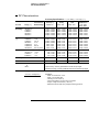
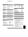
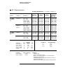
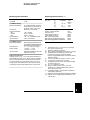
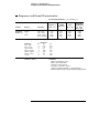
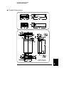
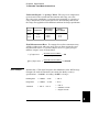
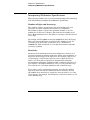
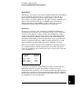
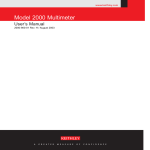
8 Specifications 8 Chapter 8 Specifications DC Characteristics DC Characteristics Accuracy Specifications ± ( % of reading + % of range ) [ 1 ] Test Current or Burden Voltage 24 Hour [ 2 ] 23°C ± 1°C 90 Day 23°C ± 5°C 1 Year 23°C ± 5°C Temperature Coefficient /°C 0°C – 18°C 28°C – 55°C 0.0030 + 0.0030 0.0020 + 0.0006 0.0015 + 0.0004 0.0020 + 0.0006 0.0020 + 0.0006 0.0040 + 0.0035 0.0030 + 0.0007 0.0020 + 0.0005 0.0035 + 0.0006 0.0035 + 0.0010 0.0050 + 0.0035 0.0040 + 0.0007 0.0035 + 0.0005 0.0045 + 0.0006 0.0045 + 0.0010 0.0005 + 0.0005 0.0005 + 0.0001 0.0005 + 0.0001 0.0005 + 0.0001 0.0005 + 0.0001 0.0030 + 0.0030 0.0020 + 0.0005 0.0020 + 0.0005 0.0020 + 0.0005 0.002 + 0.001 0.015 + 0.001 0.300 + 0.010 0.008 + 0.004 0.008 + 0.001 0.008 + 0.001 0.008 + 0.001 0.008 + 0.001 0.020 + 0.001 0.800 + 0.010 0.010 + 0.004 0.010 + 0.001 0.010 + 0.001 0.010 + 0.001 0.010 + 0.001 0.040 + 0.001 0.800 + 0.010 0.0006 + 0.0005 0.0006 + 0.0001 0.0006 + 0.0001 0.0006 + 0.0001 0.0010 + 0.0002 0.0030 + 0.0004 0.1500 + 0.0002 Function Range [ 3 ] DC Voltage 100.0000 mV 1.000000 V 10.00000 V 100.0000 V 1000.000 V Resistance [4] 100.0000 Ω 1.000000 kΩ 10.00000 kΩ 100.0000 kΩ 1.000000 MΩ 10.00000 MΩ 100.0000 MΩ 1 mA 1 mA 100 µA 10 µA 5 µA 500 nA 500 nA || 10 MΩ DC Current 10.00000 mA 100.0000 mA 1.000000 A 3.000000 A < 0.1 V < 0.6 V <1V <2V 0.005 + 0.010 0.01 + 0.004 0.05 + 0.006 0.10 + 0.020 0.030 + 0.020 0.030 + 0.005 0.080 + 0.010 0.120 + 0.020 0.050 + 0.020 0.050 + 0.005 0.100 + 0.010 0.120 + 0.020 0.002 + 0.0020 0.002 + 0.0005 0.005 + 0.0010 0.005 + 0.0020 Continuity 1000.0 Ω 1 mA 0.002 + 0.010 0.008 + 0.020 0.010 + 0.020 0.001 + 0.002 Diode Test 1.0000 V 1 mA 0.002 + 0.010 0.008 + 0.020 0.010 + 0.020 0.001 + 0.002 DC:DC Ratio 100 mV to 1000 V ( Input Accuracy ) + ( Reference Accuracy ) Input Accuracy = accuracy specification for the HI-LO input signal. Reference Accuracy = accuracy specification for the HI-LO reference input signal. Transfer Accuracy ( typical ) ( 24 hour % of range error ) 2 216 Conditions: - Within 10 minutes and ± 0.5°C. - Within ±10% of initial value. - Following a 2-hour warm-up. - Fixed range between 10% and 100% of full scale. - Using 61⁄2 digit slow resolution ( 100 PLC ). - Measurements are made using accepted metrology practices. Chapter 8 Specifications DC Characteristics Operating Characteristics [ 8 ] Measuring Characteristics DC Voltage Measurement Method: A/D Linearity: Input Resistance: 0.1 V, 1 V, 10 V ranges 100 V, 1000 V ranges Input Bias Current: Input Terminals: Input Protection: Resistance Measurement Method: Max. Lead Resistance: (4-wire ohms) Input Protection: DC Current Shunt Resistor: Input Protection: Continuity / Diode Test Response Time: Continuity Threshold: DC:DC Ratio Measurement Method: Input HI-LO Reference HI-Input LO Input to Reference Continuously integrating, multi-slope III A/D converter. 0.0002% of reading + 0.0001% of range Selectable 10 MΩ or >10 GΩ [11] 10 MΩ ±1% < 30 pA at 25°C Copper alloy 1000 V on all ranges Selectable 4-wire or 2-wire ohms. Current source referenced to LO input. 10% of range per lead for 100 Ω, 1 kΩ ranges. 1 kΩ per lead on all other ranges. 1000 V on all ranges 0.1Ω for 1A, 3A. 5Ω for 10 mA, 100 mA Externally accessible 3A, 250 V fuse Internal 7A, 250 V fuse 300 samples/sec with audible tone Adjustable from 1 Ω to 1000 Ω Input HI-LO / Reference HI-LO 100 mV to 1000 V ranges 100 mV to 10 V ranges (autoranged) Reference LO to Input LO voltage < 2 V Reference HI to Input LO voltage < 12V Measurement Noise Rejection 60 Hz ( 50 Hz ) [ 5 ] DC CMRR Integration Time 100 PLC / 1.67s (2s) 10 PLC / 167 ms (200 ms) 1 PLC / 16.7 ms (20 ms) 0.2 PLC / 3 ms (3 ms) 0.02 PLC / 400 µs (400 µs) 140 dB Normal Mode Rejection [ 6 ] 60 dB [ 7 ] 60 dB [ 7 ] 60 dB [ 7 ] 0 dB 0 dB Function DCV, DCI, and Resistance Digits 61⁄2 61⁄2 51⁄2 51⁄2 41⁄2 Readings/s 0.6 (0.5) 6 (5) 60 (50) 300 1000 System Speeds [ 9 ] Function Change Range Change Autorange Time ASCII readings to RS-232 ASCII readings to HP-IB Max. Internal Trigger Rate Max. External Trigger Rate to Memory Max. External Trigger Rate to HP-IB Additional Noise Error 0% of range 0% of range 0.001% of range 0.001% of range [10] 0.01% of range [10] 26/sec 50/sec <30 ms 55/sec 1000/sec 1000/sec 1000/sec 900/sec Autozero OFF Operation Following instrument warm-up at calibration temperature ±1°C and <10 minutes, add 0.0002% range additional error + 5 µV. Settling Considerations Reading settling times are affected by source impedance, cable dielectric characteristics, and input signal changes. Measurement Considerations HP recommends the use of Teflon or other high-impedance, low-dielectric absorption wire insulation for these measurements. Specifications are for 1-hour warm-up at 61⁄2 digits. Relative to calibration standards. 20% overrange on all ranges, except 1000 Vdc, 3 A range. Specifications are for 4-wire ohms function, or 2-wire ohms using Math Null. Without Math Null, add 0.2 Ω additional error in 2-wire ohms function. [ 5 ] For 1 kΩ unbalance in LO lead. [ 6 ] For power-line frequency ± 0.1%. [ 7 ] For power-line frequency ± 1%, subtract 20 dB. For ± 3%, subtract 30 dB. [ 8 ] Readings speeds for 60 Hz and ( 50 Hz ) operation, Autozero Off. [ 9 ] Speeds are for 41⁄2 digits, Delay 0, Autozero OFF, and Display OFF. Includes measurement and data transfer over HP-IB. [ 10 ] Add 20 µV for dc volts, 4 µA for dc current, or 20 mΩ for resistance. [ 11 ] For these ranges, inputs beyond ±17V are clamped through 100 kΩ (typical). [1] [2] [3] [4] Teflon is a registered trademark of E.I. duPont deNemours and Co. 217 8 Chapter 8 Specifications AC Characteristics AC Characteristics Accuracy Specifications Function True RMS AC Voltage [4] True RMS AC Current [4] ± ( % of reading + % of range ) [ 1 ] Frequency 24 Hour [ 2 ] 23°C ± 1°C 90 Day 23°C ± 5°C 1 Year 23°C ± 5°C Temperature Coefficient/°C 0°C – 18°C 28°C – 55°C 100.0000 mV 3 Hz – 5 Hz 5 Hz – 10 Hz 10 Hz – 20 kHz 20 kHz – 50 kHz 50 kHz – 100 kHz 100 kHz – 300 kHz [6] 1.00 + 0.03 0.35 + 0.03 0.04 + 0.03 0.10 + 0.05 0.55 + 0.08 4.00 + 0.50 1.00 + 0.04 0.35 + 0.04 0.05 + 0.04 0.11 + 0.05 0.60 + 0.08 4.00 + 0.50 1.00 + 0.04 0.35 + 0.04 0.06 + 0.04 0.12 + 0.05 0.60 + 0.08 4.00 + 0.50 0.100 + 0.004 0.035 + 0.004 0.005 + 0.004 0.011 + 0.005 0.060 + 0.008 0.20 + 0.02 1.000000 V to 750.000 V 3 Hz – 5 Hz 5 Hz – 10 Hz 10 Hz – 20 kHz 20 kHz – 50 kHz 50 kHz – 100 kHz [5] 100 kHz – 300 kHz [6] 1.00 + 0.02 0.35 + 0.02 0.04 + 0.02 0.10 + 0.04 0.55 + 0.08 4.00 + 0.50 1.00 + 0.03 0.35 + 0.03 0.05 + 0.03 0.11 + 0.05 0.60 + 0.08 4.00 + 0.50 1.00 + 0.03 0.35 + 0.03 0.06 + 0.03 0.12 + 0.05 0.60 + 0.08 4.00 + 0.50 0.100 + 0.003 0.035 + 0.003 0.005 + 0.003 0.011 + 0.005 0.060 + 0.008 0.20 + 0.02 1.000000 A 3 Hz – 5 Hz 5 Hz – 10 Hz 10 Hz – 5 kHz 1.00 + 0.04 0.30 + 0.04 0.10 + 0.04 1.00 + 0.04 0.30 + 0.04 0.10 + 0.04 1.00 + 0.04 0.30 + 0.04 0.10 + 0.04 0.100 + 0.006 0.035 + 0.006 0.015 + 0.006 3.00000 A 3 Hz – 5 Hz 5 Hz – 10 Hz 10 Hz – 5 kHz 1.10 + 0.06 0.35 + 0.06 0.15 + 0.06 1.10 + 0.06 0.35 + 0.06 0.15 + 0.06 1.10 + 0.06 0.35 + 0.06 0.15 + 0.06 0.100 + 0.006 0.035 + 0.006 0.015 + 0.006 Range [ 3 ] Additional Low Frequency Errors ( % of reading ) Frequency 10 Hz – 20 Hz 20 Hz – 40 Hz 40 Hz – 100 Hz 100 Hz – 200 Hz 200 Hz – 1 kHz > 1 kHz Slow 0 0 0 0 0 0 AC Filter Medium 0.74 0.22 0.06 0.01 0 0 Additional Crest Factor Errors ( non-sinewave ) [ 7 ] Fast –– –– 0.73 0.22 0.18 0 Crest Factor 1–2 2–3 3–4 4–5 Error ( % of reading ) 0.05% 0.15% 0.30% 0.40% Sinewave Transfer Accuracy ( typical ) Frequency 10 Hz – 50 kHz 50 kHz – 300 kHz 218 Error ( % of range ) 0.002% 0.005% Conditions: - Sinewave input. - Within 10 minutes and ± 0.5°C. - Within ±10% of initial voltage and ±1% of initial frequency. - Following a 2-hour warm-up. - Fixed range between 10% and 100% of full scale ( and <120 V ). - Using 61⁄2 digit resolution. - Measurements are made using accepted metrology practices. Chapter 8 Specifications AC Characteristics Measuring Characteristics Operating Characteristics [ 9 ] Measurement Noise Rejection [ 8 ] 70 dB AC CMRR Function ACV, ACI True RMS AC Voltage Measurement Method: Crest Factor: AC Filter Bandwidth: Slow Medium Fast Input Impedance: Input Protection: True RMS AC Current Measurement Method: Shunt Resistor: Burden Voltage: Input Protection: AC-coupled True RMS – measures the ac component of input with up to 400 Vdc of bias on any range. Maximum 5:1 at full scale 3 Hz – 300 kHz 20 Hz – 300 kHz 200 Hz – 300 kHz 1 MΩ ± 2%, in parallel with 100 pF 750 V rms all ranges Direct coupled to the fuse and shunt. AC-coupled True RMS measurement (measures the ac component only). 0.1 Ω for 1 A and 3 A ranges 1 A range: < 1 V rms 3 A range: < 2 V rms Externally accessible 3A, 250 V fuse Internal 7A, 250 V fuse Settling Considerations Applying >300 V rms (or >1 A rms) will cause self-heating in signal-conditioning components. These errors are included in the instrument specifications. Internal temperature changes due to self-heating may cause additional error on lower ac voltage ranges. The additional error will be less than 0.02% of reading and will generally dissipate within a few minutes. Digits 61⁄2 61⁄2 61⁄2 61⁄2 61⁄2 Reading/s 7 sec/reading 1 1.6 [ 10 ] 10 50 [ 11 ] System Speeds [ 11 ] , [ 12 ] Function or Range Change Autorange Time ASCII readings to RS-232 ASCII readings to HP-IB Max. Internal Trigger Rate Max. External Trigger Rate to Memory Max. External Trigger Rate to HP-IB/RS-232 [1] [2] [3] [4] [5] [6] [7] [8] [9] [ 10 ] [ 11 ] [ 12 ] AC Filter Slow Medium Fast Fast Fast 5/sec <0.8 sec 50/sec 50/sec 50/sec 50/sec 50/sec Specifications are for 1-hour warm-up at 61⁄2 digits, Slow ac filter, sinewave input. Relative to calibration standards. 20% overrange on all ranges, except 750 Vac, 3 A range. Specifications are for sinewave input >5% of range. For inputs from 1% to 5% of range and <50 kHz, add 0.1% of range additional error. For 50 kHz to 100 kHz, add 0.13% of range. 750 Vac range limited to 100 kHz or 8x10⁷ Volt-Hz. Typically 30% of reading error at 1 MHz. For frequencies below 100 Hz, slow AC filter specified for sinewave input only. For 1 kΩ unbalance in LO lead. Maximum reading rates for 0.01% of ac step additional error. Additional settling delay required when input dc level varies. For External Trigger or remote operation using default settling delay ( Delay Auto ). Maximum useful limit with default settling delays defeated. Speeds are for 41⁄2 digits, Delay 0, Display OFF, and Fast AC filter. 219 8 Chapter 8 Specifications Frequency and Period Characteristics Frequency and Period Characteristics Accuracy Specifications ± ( % of reading ) [ 1 ] Function Range [ 3 ] Frequency Frequency, Period [ 4 ] 100 mV to 750 V 3 Hz – 5 Hz 5 Hz – 10 Hz 10 Hz – 40 Hz 40 Hz – 300 kHz 24 Hour [ 2 ] 23°C ± 1°C 0.10 0.05 0.03 0.006 90 Day 23°C ± 5°C 0.10 0.05 0.03 0.01 1 Year 23°C ± 5°C 0.10 0.05 0.03 0.01 Temperature Coefficient/°C 0°C – 18°C 28°C – 55°C 0.005 0.005 0.001 0.001 Additional Low-Frequency Errors ( % of reading ) [ 4 ] Frequency 3 Hz – 5 Hz 5 Hz – 10 Hz 10 Hz – 40 Hz 40 Hz – 100 Hz 100 Hz – 300 Hz 300 Hz – 1 kHz > 1 kHz Transfer Accuracy ( typical ) 0.0005% of reading 220 61⁄2 0 0 0 0 0 0 0 Resolution 51⁄2 0.12 0.17 0.2 0.06 0.03 0.01 0 41⁄2 0.12 0.17 0.2 0.21 0.21 0.07 0.02 Conditions: - Within 10 minutes and ± 0.5°C. - Within ±10% of initial value. - Following a 2-hour warm-up. - For inputs > 1 kHz and > 100 mV. - Using 61⁄2 digit slow resolution ( 1 second gate time ). - Measurements are made using accepted metrology practices. Chapter 8 Specifications Frequency and Period Characteristics Measuring Characteristics Operating Characteristics [ 5 ] Frequency and Period Measurement Method: Function Frequency, Period Voltage Ranges: Gate Time: Reciprocal-counting technique. AC-coupled input using the ac voltage measurement function. 100 mV rms full scale to 750 V rms. Auto or manual ranging. 10 ms, 100 ms, or 1 sec Settling Considerations Errors will occur when attempting to measure the frequency or period of an input following a dc offset voltage change. The input blocking RC time constant must be allowed to fully settle ( up to 1 sec ) before the most accurate measurements are possible. Measurement Considerations All frequency counters are susceptible to error when measuring low-voltage, low-frequency signals. Shielding inputs from external noise pickup is critical for minimizing measurement errors. Digits 61⁄2 51⁄2 41⁄2 Reading/s 1 9.8 80 System Speeds [ 5 ] Configuration Rates Autorange Time ASCII readings to RS-232 ASCII readings to HP-IB Max. Internal Trigger Rate Max. External Trigger Rate to Memory Max. External Trigger Rate to HP-IB/RS-232 14/sec <0.6 sec 55/sec 80/sec 80/sec 80/sec 80/sec Specifications are for 1-hour warm-up at 61⁄2 digits. Relative to calibration standards. 20% overrange on all ranges, except 750 Vac range. Input > 100 mV. For 10 mV input, multiply % of reading error x10. [ 5 ] Speeds are for 61⁄2 digits, Delay 0, Display OFF, and Fast AC filter. [1] [2] [3] [4] 221 8 Chapter 8 Specifications General Information General Information General Specifications Power Supply: Power Line Frequency: Power Consumption: Operating Environment: Storage Environment: Operating Altitude: Rack Dimensions (HxWxD): Weight: Safety: EMI: [ 1 ] Vibration and Shock: Warranty: 100 V / 120 V / 220 V / 240 V ±10%. 45 Hz to 66 Hz and 360 Hz to 440 Hz. Automatically sensed at power-on. 25 VA peak ( 10 W average ) Full accuracy for 0°C to 55°C Full accuracy to 80% R.H. at 40°C -40°C to 70°C Up to 2,000 meters 88.5 mm x 212.6 mm x 348.3 mm 3.6 kg (8 lbs) Designed to CSA 231, UL 1244, IEC 1010-1 (1990) MIL-461C (data on file), MIL-T-28800E Type III, Class 5 (data on file) 3 years standard Accessories Included Test Lead Kit with probes, alligator, and grabber attachments. User’s Guide, Service Guide, test report, and power cord. [ 1 ] Slight accuracy degradation may result when subjected to 3 V/m radiated fields. 222 Triggering and Memory Reading HOLD Sensitivity: Samples per Trigger: Trigger Delay: External Trigger Delay: External Trigger Jitter: Memory: 0.01%, 0.1%, 1%, or 10% of reading 1 to 50,000 0 to 3600 sec ( 10 µs step size ) < 1 ms < 500 µs 512 readings Math Functions Null, Min/Max/Average, dB, dBm, Limit Test (with TTL output). dBm reference resistances: 50, 75, 93, 110, 124, 125, 135, 150, 250, 300, 500, 600, 800, 900, 1000, 1200, or 8000 ohms. Standard Programming Languages SCPI (Standard Commands for Programmable Instruments) HP 3478A Language Emulation Fluke 8840A, Fluke 8842A Language Emulation Remote Interface HP-IB (IEEE-488.1, IEEE-488.2) and RS-232C Chapter 8 Specifications Product Dimensions Product Dimensions TOP All dimensions are shown in millimeters. 223 8 Chapter 8 Specifications To Calculate Total Measurement Error To Calculate Total Measurement Error Each specification includes correction factors which account for errors present due to operational limitations of the multimeter. This section explains these errors and shows how to apply them to your measurements. Refer to “Interpreting Multimeter Specifications,” starting on page 226, to get a better understanding of the terminology used and to help you interpret the multimeter’s specifications. The multimeter’s accuracy specifications are expressed in the form: ( % of reading + % of range ). In addition to the reading error and range error, you may need to add additional errors for certain operating conditions. Check the list below to make sure you include all measurement errors for a given function. Also, make sure you apply the conditions as described in the footnotes on the specification pages. • If you are operating the multimeter outside the 23°C ± 5°C temperature range specified, apply an additional temperature coefficient error. • For dc voltage, dc current, and resistance measurements, you may need to apply an additional reading speed error or autozero OFF error. • For ac voltage and ac current measurements, you may need to apply an additional low frequency error or crest factor error. Understanding the “ % of reading ” Error The reading error compensates for inaccuracies that result from the function and range you select, as well as the input signal level. The reading error varies according to the input level on the selected range. This error is expressed in percent of reading. The following table shows the reading error applied to the multimeter’s 24-hour dc voltage specification. Range Input Level 10 Vdc 10 Vdc 10 Vdc 10 Vdc 1 Vdc 0.1 Vdc 224 Reading Error (% of reading) 0.0015 0.0015 0.0015 Reading Error Voltage ≤ 150 µV ≤ 15 µV ≤ 1.5 µV Chapter 8 Specifications To Calculate Total Measurement Error Understanding the “ % of range ” Error The range error compensates for inaccuracies that result from the function and range you select. The range error contributes a constant error, expressed as a percent of range, independent of the input signal level. The following table shows the range error applied to the multimeter’s 24-hour dc voltage specification. Range Input Level 10 Vdc 10 Vdc 10 Vdc 10 Vdc 1 Vdc 0.1 Vdc Range Error (% of range) 0.0004 0.0004 0.0004 Range Error Voltage ≤ 40 µV ≤ 40 µV ≤ 40 µV Total Measurement Error To compute the total measurement error, add the reading error and range error. You can then convert the total measurement error to a “percent of input” error or a “ppm (part-permillion) of input” error as shown below. % of input error = ppm of input error = Error Example Total Measurement Error × 100 Input Signal Level Total Measurement Error × 1,000,000 Input Signal Level Assume that a 5 Vdc signal is input to the multimeter on the 10 Vdc range. Compute the total measurement error using the 90-day accuracy specifications: ± (0.0020% of reading + 0.0005% of range). Reading Error = 0.0020% × 5 Vdc = 100 µV Range Error = 0.0005% × 10 Vdc = 50 µV Total Error = 100 µV + 50 µV = ± 150 µV = ± 0.0030% of 5 Vdc = ± 30 ppm of 5 Vdc 225 8 Chapter 8 Specifications Interpreting Multimeter Specifications Interpreting Multimeter Specifications This section is provided to give you a better understanding of the terminology used and will help you interpret the multimeter’s specifications. Number of Digits and Overrange The “number of digits” specification is the most fundamental, and sometimes, the most confusing characteristic of a multimeter. The number of digits is equal to the maximum number of “9’s” the multimeter can measure or display. This indicates the number of full digits. Most multimeters have the ability to overrange and add a partial or “1⁄2” digit. For example, the HP 34401A can measure 9.99999 Vdc on the 10 V range. This represents six full digits of resolution. The multimeter can also overrange on the 10 V range and measure up to a maximum of 12.00000 Vdc. This corresponds to a 61⁄2-digit measurement with 20% overrange capability. Sensitivity Sensitivity is the minimum level that the multimeter can detect for a given measurement. Sensitivity defines the ability of the multimeter to respond to small changes in the input level. For example, suppose you are monitoring a 1 mVdc signal and you want to adjust the level to within ±1 µV. To be able to respond to an adjustment this small, this measurement would require a multimeter with a sensitivity of at least 1 µV. You could use a 61⁄2-digit multimeter if it has a 1 Vdc or smaller range. You could also use a 41⁄2-digit multimeter with a 10 mVdc range. For ac voltage and ac current measurements, note that the smallest value that can be measured is different from the sensitivity. For the HP 34401A, these functions are specified to measure down to 1% of the selected range. For example, the multimeter can measure down to 1 mV on the 100 mV range. 226 Chapter 8 Specifications Interpreting Multimeter Specifications Resolution Resolution is the numeric ratio of the maximum displayed value divided by the minimum displayed value on a selected range. Resolution is often expressed in percent, parts-per-million (ppm), counts, or bits. For example, a 61⁄2-digit multimeter with 20% overrange capability can display a measurement with up to 1,200,000 counts of resolution. This corresponds to about 0.0001% (1 ppm) of full scale, or 21 bits including the sign bit. All four specifications are equivalent. Accuracy Accuracy is a measure of the “exactness” to which the multimeter’s measurement uncertainty can be determined relative to the calibration reference used. Absolute accuracy includes the multimeter’s relative accuracy specification plus the known error of the calibration reference relative to national standards (such as the U.S. National Institute of Standards and Technology). To be meaningful, the accuracy specifications must be accompanied with the conditions under which they are valid. These conditions should include temperature, humidity, and time. There is no standard convention among multimeter manufacturers for the confidence limits at which specifications are set. The table below shows the probability of non-conformance for each specification with the given assumptions. Specification Criteria Probability of Failure Mean ± 2 sigma Mean ± 3 sigma Mean ± 4 sigma 4.5% 0.3% 0.006% Variations in performance from reading to reading, and instrument to instrument, decrease for increasing number of sigma for a given specification. This means that you can achieve greater actual measurement precision for a specific accuracy specification number. The HP 34401A is designed and tested to meet performance better than mean ±4 sigma of the published accuracy specifications. 227 8 Chapter 8 Specifications Interpreting Multimeter Specifications Transfer Accuracy Transfer accuracy refers to the error introduced by the multimeter due to noise and short-term drift. This error becomes apparent when comparing two nearly-equal signals for the purpose of “transferring” the known accuracy of one device to the other. 24-Hour Accuracy The 24-hour accuracy specification indicates the multimeter’s relative accuracy over its full measurement range for short time intervals and within a stable environment. Short-term accuracy is usually specified for a 24-hour period and for a ±1°C temperature range. 90-Day and 1-Year Accuracy These long-term accuracy specifications are valid for a 23°C ± 5°C temperature range. These specifications include the initial calibration errors plus the multimeter’s long-term drift errors. Temperature Coefficients Accuracy is usually specified for a 23°C ± 5°C temperature range. This is a common temperature range for many operating environments. You must add additional temperature coefficient errors to the accuracy specification if you are operating the multimeter outside a 23°C ± 5°C temperature range (the specification is per °C). 228 Chapter 8 Specifications Configuring for Highest Accuracy Measurements Configuring for Highest Accuracy Measurements The measurement configurations shown below assume that the multimeter is in its power-on or reset state. It is also assumed that manual ranging is enabled to ensure proper full scale range selection. DC Voltage, DC Current, and Resistance Measurements: • Set the resolution to 6 digits (you can use the 6 digits slow mode for further noise reduction). • Set the input resistance to greater than 10 GΩ (for the 100 mV, 1 V, and 10 V ranges) for the best dc voltage accuracy. • Use 4-wire ohms for the best resistance accuracy. • Use Math Null to null the test lead resistance for 2-wire ohms, and to remove interconnection offset for dc voltage measurements. AC Voltage and AC Current Measurements: • Set the resolution to 6 digits. • Select the slow ac filter (3 Hz to 300 kHz). Frequency and Period Measurements: • Set the resolution to 6 digits. 229 8