1
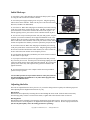
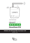
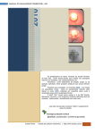
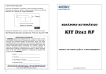
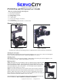
PT-2100 Pan and Tilt System User’s Guide
Make sure your kit includes the following parts:
(1)
(1)
(1)
(2)
(1)
(1)
(1)
(1)
PT-2100 Pan and Tilt Head
Dual Joystick Controller
Digital 4-Motor Controller
25’ BNC cables
7’ RJ11 Cable
12V DC Power Supply (120-220AC)
3-16” hex key
Camera Mounting Plate (includes 3 x 1/4-20 screws)
Mounting Configurations:
Hanging Configuration
Upright Configuration
The head can be mounted in the hanging position or upright position as desired without any modifications.
Mounting the camera plate:
The camera plate is mounted to the tilt system using the supplied 1/4-20 x 1/4” screws. Insert screws through the
bottom of the tilt and thread into the plate. Tighten using supplied 3/16” hex key.
Mounting camera:
Most cameras accept a 1/4-20 screw for mounting. Attach camera to the camera plate with the supplied 1/4-20 x
1/2” screw and 1/4” washer. Tighten using supplied 3/16” hex key.
Balancing camera:
(Step 1) The height of the camera platform is able to be adjusted using the adjustment slides
shown on the picture to the right. Loosen the hex bolts so that the platform can be slid up
and down the adjustment slides. Slide the platform up so that the center of the camera lens
is the same height as the center of the tilt shaft. Once the height is properly adjusted, retighten the hex bolts with the 3/16” hex key.
(Step 2) The camera plate has many slots so that the camera can be properly positioned.
Ideally, the balance point of the camera should be positioned at the very center of the tilt
platform. Mount camera to the slot that allows for the best weight balance front to back.
Some cameras have lenses that are too long to be perfectly balanced; in this case mount your
camera to the most rearward slot with the 1/4-20 x 1/2” screw.
(By performing the above steps the head will operate quieter and smoother than if the camera is left unbalanced). DON’T FORGET TO TIGHTEN THE BOLTS
Copyright 2011 Robotzone, LLC.— All Rights Reserved
OVER►
Initial Hook-up:
1. Uncoil the 7’ RJ11 cable and plug one end into the dual joystick controller. Plug the other end into the 4-motor controller.
2. Uncoil the power supply and plug it into AC power. Plug the opposing
end into the 4-motor controller. Make sure the power switch is turned off at
this time (red LED is not illuminated).
3. Uncoil one 25’ BNC cable and plug it into the BNC port found on the leg
of the pan system that is wired to the pan motor. The BNC connection will
press on and twist 1/4 turn in the clockwise direction to lock in place. Attach the opposing end to a port on the 4-motor controller and lock in place.
4. You are now ready to run the pan motor with your dual joystick. Flip the
switch on your 4-motor controller; the red light will illuminate in the “ON”
position. Move the joysticks to determine which channel you have the pan
motor connected to. Move the BNC cable to the port on the 4-motor controller that corresponds to the channel you wish to operate the pan system from.
5. Uncoil the second 25’ BNC cable and plug into the BNC port on the leg
of the pan system that is wired for the tilt motor. Plug the opposing end into
the 4-motor controller and determine which channel you wish to control the
tilt axis with in the same manner used to setup the pan axis.
6. It is advised at this time that you label the ports on the 4-motor controller
to make future set-ups simple.
7. If your pan or tilt motors operate in the opposite direction that you wish,
they can easily be reversed. Turn the power off and simply unplug the bullet
connectors found near the motors and switch them around. By reversing the
polarity of the motors they will respond to the joystick movements in the
opposite direction.
8. Your pan and tilt wiring is now complete and the PT-2100 pan and tilt
system is ready to operate.
An extra BNC port has been provided on the base of the pan system for
the optional R-2200 roll attachment or any other future upgrades that
require an additional motor.
Adjusting the belts:
The belts are adjusted from the factory, however, if you wish to change motors or pulleys the following steps will
make adjusting the belt alignment and tension very easy.
Belt Tension:
Belt tension can be adjusted by loosening the two bolts holding the motor mount. Slide the motor mount away
from the large pulley in order to increase belt tension; re-tighten bolts when desired tension is achieved.
Belt Alignment:
Belt alignment can be adjusted by loosening the clamping bolt on the motor mount. The motor can be raised and
lowered to achieve correct alignment. Re-tighten bolts when alignment is achieved. Re-check proper belt tension.
(Be sure the pinion pulley clears all rotating parts before operating)
Copyright 2011 Robotzone, LLC.— All Rights Reserved