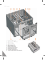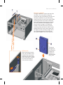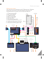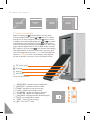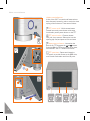
1
Origen
Thank you for purchasing this Origenae htpc enclosure.
We recommend that you read thoroughly before installation.
Origenae is not responsible for any damages due
to external causes, including but not limited to,
improper use, problems with electrical power,
accident, neglect, alteration, repair, improper
installation or improper testing.
Revision S21T.V1/02.07
Copyright © 2007 OrigenAE Technology
All rights reserved
index
S21T specifications
S21T overview
Opening the case
Removing motherboard tray
Micro ATX standoff installation
VGA bracket/loop cable
Optical disk drive installation
Optical drive bezel installation
Metal sticker fitting instructions
Hard drive installation
Hard drive configuration
PCB/cable reference diagram
TFT controls / menu operation
TFT menu guide
Hidden controls / features
Card reader & I/O ports
Touch panel software installation
4
5
7
7
8
8
9
10
10
11
12
13
14
15
16
17
18
S21T specifications
224 mm
435 mm
4
435 mm
390 mm
External dimensions (WxHxD)
435 x 224 x 390mm
Construction materials
all aluminium chassis
Motherboad support
ATX, micro ATX
PSU support
ATX PSU
PCI / AGP card support
full size
Drive bays
10 x 3.5” internal drive bays
1 x 5.25” external drive bay
Fan support
1 x 120mm low dB exhaust fans
2 x 92mm low dB intake fans
120mm low dB extractor module (optional)
Expansion slots
7
Front I/O ports
2
1
1
1
1
IR support
Microsoft IR MCE controller (optional)
IRtrans IR controller (optional)
Net weight
9.8kg
Available colours
black, silver
TFT specification
12.1” screen size (16:10 ratio)
1280 x 800 native resolution
1920 x 1080 max resolution
1 x SVGA input
12v dc input
9w power consumption
x
x
x
x
x
USB 2.0 ports
1394 port
headphone (HD & AC97)
microphone (HD & Ac97)
multi format card reader
S21T overview
S21T overview
The following diagrams (below and overleaf) highlight the main features and controls of
the S21T htpc enclosure. Further information can be found throughout this user guide.
1
2
1
2
3
4
5
6
7
8
9
10
11
12
13
14
15
16
17
18
19
-
3
4
5
6
7
8
9
13 14
15 15
10
11
12
Power button
Power LED ring
TFT power ON/OFF button*
IR receiver window
TFT stylus
Optical disk drive [bezel]
Optical disk drive eject button
12.1” touch screen TFT
I/O ports and card reader (p.17)
TFT controls (p.14)
TFT open/close button
One piece aluminum chassis
PSU bracket
Top panel fixing screw
Motherboard tray fixing screw
Removable motherboard tray
120mm low dB fan
Top panel
Extractor module vent
16 17
15 18 19 14
15
*see page 16 for auto-power on feature
5
S21T overview
1
8
1
2
3
4
5
6
7
8
9
10
11
6
-
2
3
5
4
9
Hard drive (HD) stop-rail
Optical disk drive (ODD) cage
Motor assembly
92mm low dB fan
HD mounting bracket
ODD/HD support strut
Extractor module mount
One piece aluminum chassis
Moulded back panel frame
Removable motherboard tray
120mm low dB extractor module (optional)
6
7
10
11
Opening the case / removing the motherboard tray
1
2
Opening the case.
To remove the lid of the
case, undo the 2 thumb
screws as indicated.
Carefully lift the lid from
the back but not too far DO NOT FORCE, and then
pull backwards. Reverse
procedure to replace lid.
Removing the motherboard tray.
Undo the 4 thumb screws as
indicated below. Pull the tray
backwards to remove. Reverse
this procedure when replacing
the tray, ensuring it is located
in the tray guides correctly.
7
Micro ATX standoff / VGA loop cable Installation
Micro ATX standoff installation.
When installing a micro ATX motherboard, screw
the 2 standoffs provided in the locations illustrated
above. These are for micro ATX only and MUST
NOT be installed if using a full ATX motherboard.
VGA/IR blaster bracket.
This fits into any spare expansion
slot on the back of the case.
VGA loop cable.
This cable loops the VGA signal
from the graphics card to the
12.1” TFT via the VGA/IR
bracket. It fits to the connectors
as shown, which are then
secured by turning the finger
screws. The VGA is then
connected internally (see page
14 for PCB/cable reference).
IR blaster
(Microsoft
IR PCB)
VGA input
(connector
hub PCB)
8
Optical disc drive installation
Optical disc drive (ODD) installation.
Remove the ODD cage by undoing
the 4 screws as illustrated below.
Install ODD into the cage using
the correct screws (supplied).
Re-position the cage, with drive,
and replace all screws to secure.
Adjust (forward/back) position as
necessary to ensure functionality
of ODD eject button.
9
ODD bezel / metal sticker installation
Optical disk drive (ODD) bezel installation.
The aluminum ODD bezel matches the finish of the case. The installation procedure requires that
the plastic drive bezel that comes fitted to your drive, be removed prior to installation. The drive
format icon should also be fitted to the bezel before installation. The metal sticker sheet supplied
has Blu-ray, HD-DVD or DVD icons, depending on the format being used.
Alignment
spacer
Remove the existing plastic drive bezel
from your ODD. This is usually done by
uncliping it and sliding it upwards. The
disc tray should be ejected when doing
this to gain access to the bezel.
With the tray closed, peel the back off the adhesive
foam strip on the back of the bezel. Using the
cardboard spacers, position the bezel as shown and
press firmly to ensure good adhesion. Eject the tray
to remove the spacers (a gentle tug may be required).
Metal sticker fitting instructions.
Ensure the bezel is free from dirt of grease. Peel and fold back the yellow backing sheet, revealing
only the icon you intend to use. Carefully position the icon as central as possible, then apply even
pressure over the entire area. Peel off the plastic film (and unused icons) to reveal you handy work!
TOP
TOP
foam
tape
10
Hard drive installation
Hard drive installation.
To begin installation, remove the stop-rails
as shown. You may need to loosen the
screws first with a screwdriver. Drives must
always be installed with the label facing
toward the front of case. Screw three rubber
mounting screws into the drive as shown
below (the screw arrangement is mirrored
for drives installed on the opposite side).
Use the chart on page 12 to determine
location, then lower the drive into place,
carefully guiding the bottom rubber mount
straight down the outer mount guide until
the upper mounts are sitting snugly at the
top of opposing guides. Once all drives
have been installed, secure the stop-rails.
HD stop-rails.
When removing the stoprails, only the back screw
need be fully unscrewed loosening the front thumb
screw is all that’s required
to remove the stop-rail
in the direction shown.
This screw
arrangement
is mirrored for
hard drives
installed on
the other side
of the case.
Hard drive configuration
Number of hard drives to be installed
1
2
3
4
5
6
7
8
9
10
Optimum position for maximised airflow and cooling
L
L
L
R
L
L
R
L
L
L
1
LEFT
R
R
L
2
3
Hard drive configuration.
In order to maximise airflow
and cooling of the hard drives,
use the chart on the left to
determine the optimum install
configuration for the number
of drives to be installed. When
more than 6 drives are required,
careful motherboard and PCI
card selection is recommended,
as in some cases M/B connector
pin position or an oversized
graphics card may inhibit some
drive configurations. If this
occurs, the drive positions can
be reversed (left to right) or the
drive spacing decreased as
needed. Always try to maximise
the airflow wherever possible.
4
R
L
drive on the left side only
L
R
drive on the right side only
5
6
7
8
9
10
drive on both sides
RIGHT
This diagram illustrates
a five HD configuration
using the chart above.
12
PCB/cable reference diagram
PCB/cable reference diagram.
This is a general overview illustrating how the S21T PCBs interconnect. PCBs/cables
dimmed in grey, come as part of an IR kit (sold separately). Please refer to your
motherboard manual for the location of the correct ports and header pins.
1
2
3
4
5
6
7
8
9
10
11
-
TFT open/close button PCB
S21T connector hub PCB
TFT power on/off PCB
MCE/TFT IR module PCB
Main power button PCB
Motor control PCB
Front I/O ports & USB hub PCB
Microsoft IR MCE (or IR Trans) control PCB
IR blaster output (Microsoft controller only)
VGA/IR blaster PCB (expansion slot bracket)
VGA input (loop cable from graphics card)
TFT module
1
2
ATX standby
cable
M/B
(power
switch)
8
3
5
4
power
(MOLEX)
M/B (2xUSB)
motor
M/B
M/B
(1394) (audio)
IR blaster
(Microsoft IR PCB)
2xUSB
(from hub)
6
7
9
10
11
13
TFT controls / menu operation
12.1 inch TFT
(261x163mm)
aspect ratio
16:10
resolution
1280x800
TFT controls / menu operation
Begin by pressing the
(menu/set) button to bring up the
and
on screen display (OSD). Use the
buttons to navigate
through the 10 menu categories. Press the
button to select
a category, then (where appropriate) use to
and
to increase
or decrease the value as desired. Press the
button again to
confirm the setting and repeat the process until you have made
all the required adjustments. To exit the OSD, simply locate the
EXIT category (10/10) and press
(it will also exit automatically
after approximately 10 seconds of inactivity). The menu guide
on the next page shows the route [in grey] and the adjustment
sequence [in orange] for each menu category (each assumes
you are not already in the menu, with the exception of Exit).
TFT power on/off*
Menu/set
Value up
Value down
*see page 16 for auto-power on feature
1
2
3
4
5
6
7
8
9
10
14
BRIGHTNESS - adjusts the picture brightness.
CONTRAST - adjusts the picture contrast.
PHASE - adjusts the noise of the image.
CLOCK - adjusts video sampling clock.
H POSITION - adjusts the image horizontally.
V POSITION - adjusts the image vertically.
LANGUAGE - language selection (default English).
AUTO - auto image adjust wizard.
RESET - resets to factory setting.
EXIT - exits the TFT menu.
supports
1920x1080
TFT menu guide
Brightness.
follow the steps below to adjust brightness.
V position.
follow the steps below to adjust V position.
5
Contrast.
follow the steps below to adjust contrast.
1
Phase.
follow the steps below to adjust phase.
2
Clock.
follow the steps below to adjust clock speed.
3
H position.
follow the steps below to adjust H position.
Language (default is English).
follow the steps below to change language.
4
Auto-adjust wizard.
follow the steps below to auto-adjust image.
3
Reset to factory settings.
follow the steps below to reset settings.
2
Exit.
follow the steps below to exit OSD.
4
15
Hidden controls/features
Hidden controls/features
A few of the S21T’s controls and features have
been discreetly located in order to retain the clean
styling of the enclosure. These are as follows:
TFT power on/off - Quick access button
located near main power button with same
functionality as the power button on the TFT
TFT stylus location - Press to release
lock, pull out to remove. Slide stylus into the
opening (tip first) and press to lock and stow
>auto
Auto-power on feature - Located on the
and
buttons.
back of the TFT, between the
Switched ON the TFT auto-powers up on boot,
switched OFF the TFT remains off on boot.
>auto
TFT open/close - Opens and closes the
TFT panel, to provide access to the ODD drive,
multi-format card reader and front I/O ports.
(switched ON)
>auto
16
Multi-format card reader & I/O ports
Multi-format card reader & I/O ports
The S21T comes fitted with a multi-format
card reader as well as front audio, USB and
1394 ports. The [internal] USB hub feeds the
2 front USB ports as well as the IR control
and TFT touch panel, freeing up USB
connectors on the motherboard. The front
audio ports support both AC97 and
HD audio standards, while the card reader
supports all the card formats listed below.
1
1
2
3
4
5
6
7
8
-
1
2
3
4
5
6
7
8
9
10
11
12
13
USB port
1394 port
Compact flash reader
Multi format reader
Card reader power LED
Activity indicator LED
Audio in socket
Audio out socket
Compact Flash Card TYPE I
Compact Flash Card TYPE II
Compact Flash Ultra Card TYPE I 45 X
Compact Flash Ultra Card TYPE I 80 X
Compact Flash Ultra Card TYPE I 120 X
Compact Flash Ultra II Card TYPE I
Compact Flash Extreme Card
Compact Flash Extreme III Card
Compact Flash ELITE PRO Card
Compact Flash Ultimate Card 100X
Compact Flash Ultra-X Card 140X
IBM Micro Drive Card
Sony Micro Drive Card
14 Smart Media Card
15 XD-Picture Card
16
17
18
19
Secure Digital Card
Secure Digital Ultra II Card
Secure Digital Extreme Card
Secure Digital Extreme III Card
2
1
20
21
22
23
24
25
26
27
28
29
30
31
Secure Digital Ultra II Plus Card
Secure Digital Card 45X
Secure Digital PRO Card 66X
Secure Digital Card 80X
Secure Digital Card 133X
Secure Digital Card 150X
Mini Secure Digital Card
Mini Secure Digital Ultra II Card
Mini Secure Digital Card 80X
Mini Secure Digital PRO Card
Micro Secure Digital Card
Micro Secure Digital Ultra II Card
32
33
34
35
36
Multi Media Card
Multi Media PRO Card
Multi Media Plus Card
Reduced Sized Multi Media Card
Reduced Sized Multi Media Mobile Card
37 Memory Stick
38 Memory Stick
(With memory select function)
3
5
6
4
7
8
39 Memory Stick (Magic Gate / High
Speed data transfer compatible)
40 Memory Stick
(Magic Gate / High Speed data transfer
compatible with memory select function)
41 Memory Stick Pro
42 Magic Gate Memory Stick
43 Magic Gate Memory Stick
44 Memory Stick Pro HS
45 Memory Stick Pro Ultra II
46 Memory Stick Pro Extreme
47 Memory Stick Pro Extreme III
48 Memory Stick Pro
49 Memory Stick Pro Duo
50 Memory Stick Pro Duo HS
51 Memory Stick Pro Duo
52 Memory Stick Duo (Magic Gate / High
Speed data transfer compatible)
53 Memory Stick Pro Duo
54 Magic Gate Memory Stick Duo
55 Magic Gate Memory Stick Duo
56 Memory Stick ROM
NOTE: Card adapter required for some formats
17
Touch panel software installation
x
Touch panel software installation.
In order to use the touch panel, you must first install the
TouchKit software from the install CD provided or from our
website. To start the software installation, double click on
the setup.exe file located in the TouchKit folder.
1 After opening the setup.exe
file, the install will begin with
the above prompt. Click ‘Next’
to continue.
4 The touchscreen controller
should already be connected
if you have correctly
connected all cables inside
your chassis. Click ‘OK’.
18
2 Ensure that ‘Install PS/2
interface driver’ is not
selected and click ‘Next’.
5 If you intend to use spaning
mode with multiple monitors,
please select ‘Support MultiMonitor Systems’. Click ‘Next’
to continue.
3 Select ‘None’ and click ‘Next’.
After completing the install, the
TouchKit software will perform
a 4 point calibration.
6 Change the TouchKit
software install folder if
required and click ‘Next’
to continue.
Touch panel software installation
7 Change the Program
Folder name if required and
click ‘Next’ to continue.
8 Click ‘Yes’ to perform a
4 point calibration. This is
required for proper touch
screen operation.
9 The software will now scan
and install the touch screen
device. The TouchKit calibration
procedure will follow.
Press the blinking X symbol until it stops blinking
x
10 To perform the calibration, press and hold down
the X that blinks in the corner of the screen, until it
disappears. Repeat this procedure with each of the
4 X’s that appear. On completion of this, the touch
screen will be calibrated and ready for use.
x
19
Origen
Global HQ
#209 Baeksan B/D
763-2 Hengsin-Dong
Dukyang-Gu
Goyang City
Gyounggi-Do
412-220 South Korea
Website
www.origenae.com