1
EnviroMon
User's Guide
emw.en-6
Copyright 2004-2008 Pico Technology Limited. All rights reserved.
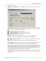
Contents
I
Contents
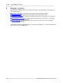
1 Introduction
.....................................................................................................................................1
1 Safety...........................................................................................................................................2
warning
...........................................................................................................................................3
2 The equipment
...........................................................................................................................................4
3 The software
...........................................................................................................................................5
4 Legal information
2 Configuration
.....................................................................................................................................6
...........................................................................................................................................6
1 Who will
be responsible for the system?
2 What...........................................................................................................................................6
do you want to measure?
...........................................................................................................................................7
1 Temperature
2 Humidity...........................................................................................................................................7
...........................................................................................................................................7
3 Electric current
...........................................................................................................................................8
4 Other parameters
3 Setting...........................................................................................................................................8
alarms
...........................................................................................................................................8
4 In the event of power failure
...........................................................................................................................................9
5 Data storage
and analysis
...........................................................................................................................................10
6 Remote data collection
...........................................................................................................................................10
7 Equipment
placement
...........................................................................................................................................10
8 Security
...........................................................................................................................................10
9 System
testing
3 Equipment.....................................................................................................................................11
...........................................................................................................................................11
1 Connections
1 Types of...........................................................................................................................................11
network
...........................................................................................................................................12
2 Connectors
...........................................................................................................................................13
3 Screw terminal
connections
4 Sensor ...........................................................................................................................................13
connections
...........................................................................................................................................14
5 EL020 sensor
adapter
...........................................................................................................................................15
2 Sensors
...........................................................................................................................................15
1 EL015 temperature
sensor
...........................................................................................................................................15
2 EL030 temperature and humidity sensor
3 TA011 ...........................................................................................................................................15
current clamp
...........................................................................................................................................16
4 SE0xx thermocouples
...........................................................................................................................................16
3 Loggers
...........................................................................................................................................16
1 EL005 logger
2 Logger ...........................................................................................................................................17
internal parameters
...........................................................................................................................................18
4 Converters
...........................................................................................................................................18
1 Introduction
...........................................................................................................................................18
2 EL001 temperature
converter
...........................................................................................................................................19
3 EL016 voltage
converter
...........................................................................................................................................19
4 EL026 temperature
and humidity converter
...........................................................................................................................................20
5 EL037 voltage
and 4-20mA converter
...........................................................................................................................................21
6 EL040 current
monitor converter
...........................................................................................................................................22
7 EL041 thermocouple
converter
...........................................................................................................................................23
5 Alarm
devices
...........................................................................................................................................23
1 EL006 remote
alarm
...........................................................................................................................................23
2 EL018 dialler
adapter and battery backup
Copyright 2004-2008 Pico Technology Limited. All rights reserved.
emw.en
II
EnviroMon User's Guide
...........................................................................................................................................25
3 EL042 alarm
& relay unit
...........................................................................................................................................30
6 Package
systems
1 Current...........................................................................................................................................30
monitoring kit
4 Getting started
.....................................................................................................................................31
...........................................................................................................................................31
1 Installation
of a package system
...........................................................................................................................................31
2 General
installation instructions
...........................................................................................................................................31
1 Identifying
the equipment
...........................................................................................................................................32
2 Connecting
up the equipment
...........................................................................................................................................33
3 Installing
the software
4 Setting ...........................................................................................................................................33
converter addresses
...........................................................................................................................................34
5 Calibrating
humidity converters
...........................................................................................................................................34
6 Configuring
the system
7 Looking...........................................................................................................................................36
at current readings
...........................................................................................................................................36
8 Displaying
a graph
...........................................................................................................................................37
9 Saving and
restoring configurations and data
5 Display options
.....................................................................................................................................38
...........................................................................................................................................39
1 Monitor
window
...........................................................................................................................................40
2 Monitor window with deviation alarms
...........................................................................................................................................41
3 Graph
window
...........................................................................................................................................42
1 Axis control
buttons
...........................................................................................................................................43
4 Summary
window
...........................................................................................................................................44
5 Spreadsheet window
...........................................................................................................................................46
6 Events
window
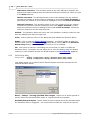
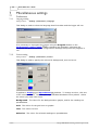
6 Main settings
.....................................................................................................................................47
...........................................................................................................................................48
1 General
configuration info panel
...........................................................................................................................................49
1 Sampling
interval dialog
...........................................................................................................................................50
2 Temperature
display
...........................................................................................................................................50
3 Alarm behaviour
4 Holiday...........................................................................................................................................51
dates
...........................................................................................................................................52
5 Site information
6 Summer...........................................................................................................................................52
time dates
...........................................................................................................................................53
7 Data storage
8 Scale ...........................................................................................................................................54
2 User...........................................................................................................................................55
list dialog
...........................................................................................................................................56
1 User information
...........................................................................................................................................57
2 Password
dialog
...........................................................................................................................................57
3 Logger
dialog
...........................................................................................................................................59
1 Converter
list
...........................................................................................................................................60
2 Add converter
3 Logger ...........................................................................................................................................61
options
4 Logger ...........................................................................................................................................62
dial-up options
...........................................................................................................................................63
5 Network
diagnostics
...........................................................................................................................................64
6 Voltages
7 Logger ...........................................................................................................................................64
list
...........................................................................................................................................65
4 Sensor
list dialog
1 Sensor ...........................................................................................................................................66
information dialog
2 Sensor ...........................................................................................................................................67
alarm
...........................................................................................................................................68
5 Deviation
Alarm dialog
...........................................................................................................................................69
1 Deviation
Alarm Setup dialog
emw.en
Copyright 2004-2008 Pico Technology Limited. All rights reserved.
Contents
III
...........................................................................................................................................70
2 EL042 Setup
dialog
3 Nested...........................................................................................................................................71
deviation alarms
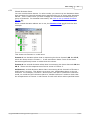
7 Miscellaneous
.....................................................................................................................................72
settings
...........................................................................................................................................72
1 Preferences
...........................................................................................................................................72
1 Language
dialog
2 Colours...........................................................................................................................................72
dialog
3 Sounds ...........................................................................................................................................73
dialog
...........................................................................................................................................74
2 Monitor
...........................................................................................................................................74
1 Select parameters
dialog
3 View...........................................................................................................................................75
...........................................................................................................................................75
1 Print dialog
...........................................................................................................................................75
2 Graph options
dialog
...........................................................................................................................................76
3 Spreadsheet
options
...........................................................................................................................................77
4 Event options
...........................................................................................................................................77
5 Event information
dialog
8 How to........................................................................................................................................78
1 How...........................................................................................................................................78
to configure a system
...........................................................................................................................................79
2 How to use multiple loggers
3 How...........................................................................................................................................80
to use a dial-up modem
4 How...........................................................................................................................................80
to measure parameters other than temperature
5 How...........................................................................................................................................81
to set up a scaling table
1 How to...........................................................................................................................................83
supply a user-defined scaling file
6 How...........................................................................................................................................85
to transfer data to other applications
7 How...........................................................................................................................................86
to set up a deviation alarm
8 How...........................................................................................................................................91
to set up nested deviation alarms
9 How...........................................................................................................................................95
to display data on a web site
...........................................................................................................................................95
1 Safe method
...........................................................................................................................................96
2 Interactive
method
...........................................................................................................................................97
10 How
to export data from the command line
9 Drivers .....................................................................................................................................99
...........................................................................................................................................99
1 Windows
drivers
2 API ...........................................................................................................................................99
...........................................................................................................................................99
1 em_open
...........................................................................................................................................99
2 em_close
...........................................................................................................................................99
3 em_get_sensors
...........................................................................................................................................100
4 em_get_current
...........................................................................................................................................100
5 em_open_reading
...........................................................................................................................................100
6 em_get_reading
3 C ...........................................................................................................................................101
4 C++...........................................................................................................................................101
...........................................................................................................................................101
5 Delphi
...........................................................................................................................................101
6 LabVIEW
10 Troubleshooting
.....................................................................................................................................102
and maintenance
...........................................................................................................................................102
1 Troubleshooting
...........................................................................................................................................103
2 Maintenance
...........................................................................................................................................103
3 Calibration
Copyright 2004-2008 Pico Technology Limited. All rights reserved.
emw.en
IV
EnviroMon User's Guide
11 File formats
.....................................................................................................................................106
and other useful information
...........................................................................................................................................106
1 Program
files
...........................................................................................................................................106
2 Envimon.ini
...........................................................................................................................................111
3 .RDG
files
...........................................................................................................................................112
4 EMWEVENT.LOG
...........................................................................................................................................112
5 DDE
12 Communications
.....................................................................................................................................113
protocols
...........................................................................................................................................113
1 EnviroMon
logger protocol
13 Messages
.....................................................................................................................................116
...........................................................................................................................................116
1 Computer
messages
...........................................................................................................................................116
2 Converter
light
Index..............................................................................................................................................117
emw.en
Copyright 2004-2008 Pico Technology Limited. All rights reserved.
Introduction
1
1
Introduction
The EnviroMon system is designed for long-term recording of data from a number of
locations. It offers the following features:
Permanent retention of recorded data on your PC
Wide range of data display and analysis options
Easy-to-use software
Telephone-style connections for easy installation
Modular system for easy upgrades
A wide range of options to report alarm conditions
Support for remote data download (modem, GSM etc.)
Copyright 2004-2008 Pico Technology Limited. All rights reserved.
emw.en
2
1.1
EnviroMon User's Guide
Safety warning
We strongly recommend that you read the general safety information below before
using your product for the first time. If the equipment is not used in the manner
specified, then the protection provided may be impaired. This could result in damage
to your computer and injury to yourself or others.
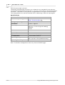
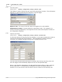
Maximum input range
The EnviroMon system is designed for use with many different converters, sensors
and signals.
Converter Designed input range
Max input voltage
EL001
EL026
EL016
N/A
N/A
±30 V
EL037
EL040
EL041
Cannot measure voltages
Cannot measure voltages
0 V to +2.5 V
-2.5 V to +2.5 V
-10 V to +10 V
4 to 20 mA
1 V RMS
±60 mV
±30 V
±30 V
±10 V
Any voltages in excess of the maximum input voltage specified in the above table may
cause permanent damage to the unit.
Mains (line) voltages
Pico products are not designed for use with mains (line) voltages.
Product grounding
The ground of every product is connected directly to the ground of your computer
through the provided interconnecting cable. This is done in order to minimise
interference. Always use the provided cable to attach the product to your computer.
You must take care to avoid connecting the ground input of the products to anything
that may be at some voltage other than ground. If in doubt, use a meter to check
that there is no significant AC or DC voltage between the ground input and the point
to which you intend to connect it. Failure to check may cause damage to the products
and your computer, and could cause injury to yourself or others.
Take great care when measuring near mains equipment. If a sensor is accidentally
connected to mains voltages, you risk damage to the converters and your computer,
and your computer chassis may become live.
You should assume that the products do not have a protective safety earth.
Configuration errors or use on voltages outside the maximum input range can be
hazardous.
Repairs
The units contains no user-serviceable parts. Repair or calibration of the units
requires specialised test equipment and must be performed by Pico Technology or its
authorised distributors.
emw.en
Copyright 2004-2008 Pico Technology Limited. All rights reserved.
Introduction
1.2
3
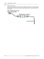
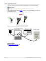
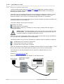
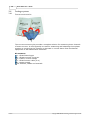
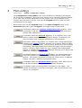
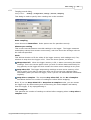
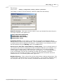
The equipment
An EnviroMon system consists of the following items:
Computer
Logger
Multiple converters
Alarm options
The following diagram shows how a typical system might be set up:
The EnviroMon PC application performs the following tasks:
System configuration
Long-term data storage
Display, analysis and printing of recorded data
The computer can communicate with loggers using each of the following methods:
Direct connection to a local logger
Telephone modem to a logger on a remote site
Radio link, for short-range connection to sites not serviced by telephone
GSM telephone, for remote or mobile applications
The logger stores data continuously, even when the computer is turned off or
disconnected, or the mains (line) power fails.
The logger connects to a number of converters that take measurements. The
converters can be up to 400 metres away from the logger, and are connected using a
single, low-cost, telephone cable that forms a 'network' between the logger and the
converters.
Copyright 2004-2008 Pico Technology Limited. All rights reserved.
emw.en
4
1.3
EnviroMon User's Guide
The software
EnviroMon is used both to configure an EnviroMon system, and to extract and analyse
data from the system. To run EnviroMon under Windows XP (SP2) or Vista:
1.
2.
3.
4.
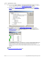
Click the Start button
Select Programs
Select Pico Technology
Select EnviroMon
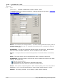
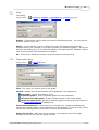
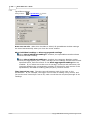
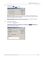
When you first start up the EnviroMon software, the system displays an empty
Monitor window 39 . Click Settings on the menu bar, then select Configuration
and Change to set up the system.
The top button on the Configuration control panel selects a guided tour. This will
take you, step by step, through the process of setting up a simple system.
The final stage of configuring a system is to click the Program button. This writes
the configuration to the logger.
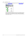
When you start up the EnviroMon software after the system has been configured, the
software transfers the readings stored in the logger to a data file on your computer,
then displays the Monitor window 39 , 39 which shows the current value of each
measured parameter.
emw.en
Copyright 2004-2008 Pico Technology Limited. All rights reserved.
Introduction
1.4
5
Legal information
The material contained in this release is licensed, not sold. Pico Technology grants a
licence to the person who installs this software, subject to the conditions listed below.
Access
The licensee agrees to allow access to this software only to persons who have been
informed of these conditions and agree to abide by them.
Usage
The software in this release is for use only with Pico products or with data collected
using Pico products.
Copyright
Pico Technology claims the copyright of, and retains the rights to, all material
(software, documents etc.) contained in this release. You may copy and distribute the
entire release in its original state, but must not copy individual items within the
release other than for backup purposes.
Liability
Pico Technology and its agents shall not be liable for any loss, damage or injury,
howsoever caused, related to the use of Pico Technology equipment or software,
unless excluded by statute.
Fitness for purpose
As no two applications are the same, Pico Technology cannot guarantee that its
equipment or software is suitable for a given application. It is your responsibility,
therefore, to ensure that the product is suitable for your application.
Mission-critical applications
This software is intended for use on a computer that may be running other software
products. For this reason, one of the conditions of the licence is that it excludes
usage in mission-critical applications, such as life-support systems.
Viruses
This software was continuously monitored for viruses during production, but you are
responsible for virus-checking the software once it is installed.
Support
If you are dissatisfied with the performance of this software, please contact our
technical support staff, who will try to fix the problem within a reasonable time. If
you are still dissatisfied, please return the product and software to your supplier
within 28 days of purchase for a full refund.
Upgrades
We provide upgrades, free of charge, from our web site at www.picotech.com. We
reserve the right to charge for updates or replacements sent out on physical media.
Trademarks
Windows is a registered trademark of Microsoft Corporation. Pico Technology and
EnviroMon are internationally registered trade marks of Pico Technology.
Copyright 2004-2008 Pico Technology Limited. All rights reserved.
emw.en
6
2
EnviroMon User's Guide
Configuration
EnviroMon is a very flexible system. It is made up of a number of separate modules,
and you simply choose the modules that you need to do the job. In addition, there
are several software options that can be configured so that the logger will do exactly
what you want.
This section describes the points that you should consider when setting up an
EnviroMon system.
2.1
Who will be responsible for the system?
For a small configuration, one person can easily install the system and operate it
daily.
Larger systems are often installed by external contractors, but it is essential to have
someone within the company who will be responsible for maintaining the system once
it is installed. This person should be involved at the earliest stages in the planning of
the system, so that they understand how it works and can easily make small changes
to the system as requirements change.
2.2
What do you want to measure?
EnviroMon takes readings from a number of sensors distributed around a site. These
sensors are connected to converters that transform the analogue signals from the
sensor into digital signals, which can then be transmitted reliably and accurately to
the logger. The type of sensor and converter that you require depends on what you
wish to measure.
emw.en
Copyright 2004-2008 Pico Technology Limited. All rights reserved.
Configuration
2.2.1
7
Temperature
EnviroMon provides full support for two different temperature measuring techniques.
It can also work with other techniques if required.
Precision thermistors are inexpensive and highly accurate (0.3 °C) , but only over a
limited temperature range, for example -40 °C to 30 °C or 0 °C to 70 °C.
Thermocouples work over a wide range, and are available in a wide variety of
probes from a large number of suppliers. Connectors are standardised, so
thermocouples from different suppliers are interchangeable.
Thermistors
The standard EL015 temperature sensor is a precision thermistor sealed in a stainless
steel cylinder. The sensor is fitted with a 5-metre cable and a connector which plugs
straight into an EL001 temperature converter. Each EL001 can accept three sensor
inputs. The sensor cable can be extended to a maximum of about 100 metres,
introducing an error of less than 0.3 °C in the temperature measurement.
At temperatures below 0 °C, the cable may become brittle and must not be flexed. At
temperatures over 70 °C, the cable may become soft and easily damaged.
The EL015 temperature sensor has an accuracy of 0.2 °C over the range 0 °C to 30
°C and 0.3 °C over the range to -30 °C to +70 °C. Outside this range, we
recommend the use of Type K sensors.
Thermocouples
The 4-channel EL041 22 thermocouple converter is designed to be used with any type
of thermocouple with a miniature thermocouple connector across a wide range of
temperatures (the range depends on the thermocouple used). The EL041 can also be
used to measure ±60 mV signals.
When extending thermocouple cables, it is essential to use thermocouple extension
cable and connectors of the same type.
2.2.2
Humidity
EnviroMon can measure humidity using the EL030 temperature and humidity sensor
and EL026 converter. The converter contains calibration information for the sensor,
so the two units are supplied as a set. The EL030 contains both a temperature sensor
and a humidity sensor. The humidity sensor has a calibrated accuracy of 2.5%.
2.2.3
Electric current
EnviroMon can measure current with the three-channel EL040 current monitor
converter 21 , which has a 1 volt AC RMS input range, making it suitable for use with a
wide range of current transformers.
Measuring mains current
The TA011 current clamp 15 is ideal for measuring mains current for industrial or
home applications. These clamps can be purchased separately or as a current
monitoring kit 30 designed for monitoring 3-phase supplies. The kit includes the
logger, current monitor converter and 3 current clamps.
Copyright 2004-2008 Pico Technology Limited. All rights reserved.
emw.en
8
2.2.4
EnviroMon User's Guide
Other parameters
The following two general-purpose converters are suitable for use with the EnviroMon
system:
EL016 8-channel voltage converter (no longer manufactured)
EL037 3-channel voltage / 4-20 mA converter (4 channels with EL005)
The EL016 has eight inputs that can measure signals between 0 and 2.5 volts.
EnviroMon can be programmed to convert the voltages into some other units (for
example, pressure) and display them in those units.
The EL037 has 4 inputs (of which only 3 are available when used with the EL008) that
can be configured to measure 2.5 volts, 10 volts and 4-20 mA. EnviroMon can be
programmed to convert the measurements into some other units (for example,
pressure) and display them in those units.
Bear in mind when selecting sensors that EnviroMon is a low-power system that can
carry on running when mains (line) power fails. Where possible, select low-power
sensors. If it is essential to use a sensor that requires a lot of power (for example gas
sensors), you should consider providing a local power supply.
2.3
Setting alarms
EnviroMon can be configured to sound an alarm if a measurement (such as
temperature) goes out of range (high or low) or if a sensor fails. For many
applications, it is not necessary to have alarms for all sensors, so the alarm function
for any sensor can be disabled. It is also possible to enable the alarm only during
certain time ranges, for example during working hours (eg 9 to 5, Monday to Friday).
It may be desirable to have an alarm on sensor failure, but not on temperature out of
range. This can be done by leaving the alarm enabled and setting a wide temperature
range. If the temperature normally goes out of range for short periods, it is possible
to hold off (delay) alarms for a specified period. For example, if a freezer periodically
goes through a defrost cycle lasting 15 minutes, an alarm holdoff of 20 minutes would
prevent the defrost cycle from causing alarms.
The high and low threshold, disable and holdoff can be set individually for each
sensor. It may be necessary to use a remote audible alarm, either in the work area
or in a security control room. This can be linked to the logger using the network
cable. If it is necessary to respond to alarms when the site is unmanned, the alarm
dialler module can make telephone calls to several numbers and deliver a voice
message.
2.4
In the event of power failure
In the event of a power failure, the EL005 logger will continue operating from its
internal battery backup. This internal battery recharges automatically when mains
power is restored.
For some applications, it is not necessary to collect or store data if mains power fails.
emw.en
Copyright 2004-2008 Pico Technology Limited. All rights reserved.
Configuration
2.5
9
Data storage and analysis
Data storage and analysis requirements vary enormously, depending on the
application. There are three main options:
Monitor temperatures - use the logger only for immediate temperature monitoring
and alarms
Print out reports at regular intervals, directly from the logger
Store the data on a computer
The logger can print the current temperatures, and a periodic summary showing the
minimum, maximum and average readings together with the number of alarms and
the total alarm duration. This approach is useful if there is not space for a computer,
or if staff are not familiar with computers. These reports can be printed out either at
regular intervals, or on request.
If a computer is used, data is transferred to the computer automatically each time the
user runs the EnviroMon program on the computer. Storing data on the computer has
a number of advantages:
Data can easily be backed up for added security (see Saving and Restoring
Configurations and Data 37 )
If the computer already has access to a printer, it is not necessary to buy a
separate printer for the logger
The computer software offers a wider range of report formats
It is possible to transfer data to other applications for further analysis
The computer need not be on the same site as the logger (see remote data access)
Once data is stored on the computer, it can be processed to create a number of
outputs:
A spreadsheet-style display, which can be transferred to a spreadsheet for further
analysis
A graph of readings against time, over periods from hours to years
A period summary which shows the minimum, maximum and average reading for
each sensor during the period, together with the number of alarm events and the
total alarm duration
A list of alarm events. It is possible to add notes about action taken on alarm.
It is possible to specify a backup path for files, which can either be a diskette or a
network drive. If you specify a diskette, the backup should be done manually, using
the Backup option on the File menu. If you specify a network drive, you can also
request an automatic backup each time you exit from the program.
It is also possible to specify that old files should be deleted after a period of time. The
options are:
Never
Delete after a month
Delete after a quarter
Delete after a year
If you are collecting data every minute, the size of the data file will be about 1.6 MB
per sensor per year. Most computers have at least 1000 MB of disk space, so it is not
usually necessary to delete old data.
Copyright 2004-2008 Pico Technology Limited. All rights reserved.
emw.en
10
2.6
EnviroMon User's Guide
Remote data collection
It is possible to access logger data remotely using either a radio modem or a
telephone modem.
Radio modem
One computer can maintain radio modem links to several remote loggers. Because
EnviroMon requires very little power, the remote loggers can easily operate using a
battery that is kept charged using a solar panel. The logger has built-in power-saving
features to turn off the radio modem when it is not required.
Warning: In order to comply with current legislation, only use radio modems that
comply with the RTTE directive.
Telephone modem
The EnviroMon software running on a PC can use a modem to make a telephone call
to a remote logger, then extract data from the logger and terminate the connection.
The logger can be configured to permit the modem to answer telephone calls only
during a narrow time range. This means, for example, that the logger data can be
downloaded at night using a telephone line that is allocated for other uses during the
day.
2.7
Equipment placement
Each EnviroMon converter turns sensor inputs into digital signals, which can be
transmitted quite long distances through the network cable. Converters should be no
more than 400 metres from the logger. The logger can therefore be placed wherever
information is required, for example in an office area, and the converters can be
placed near where parameters are to be measured.
Thermistor sensors are supplied with a 5-metre cable that can be extended up to 100
metres. Alarm relay and dialler modules are best placed close to the logger, to
minimise the risk that a break in the network could prevent the logger from operating
the relay or dialler.
2.8
Security
The EnviroMon software normally allows full access to both the data display and
configuration functions. If, however, you enter details of users, you can specify which
users are allowed to access the configuration menu.
2.9
System testing
It will be necessary to check that all parts of the system work. This is essential once
the system is installed, and should be repeated at least yearly thereafter. We
recommend that you create a checklist of features to test while you are deciding what
the configuration will be, and you can then use this checklist once the system is
installed. If possible, you should operate the system for some time to ensure that it is
working correctly, before you start to rely on the results.
When deciding on tests, the test should be as lifelike and as complete as possible. For
example, if you are using a dialler, you should simulate a fault, then verify that the
logger activates that dialler, the dialler calls the correct telephone numbers, and the
persons called understand how to acknowledge the call.
emw.en
Copyright 2004-2008 Pico Technology Limited. All rights reserved.
Equipment
3
11
Equipment
The network is a four-wire cable which carries power and data between the logger,
converters and optional equipment such as remote alarms. The logger can be
attached anywhere along the network cable. The network will operate correctly with
about 400 metres of standard network cable between the logger and the furthest
converter, but this distance can be increased to a kilometre or more by using thicker
cable.
The network can be built in the following four ways:
Connect each converter to the next using EL003 network cables. Each cable is 5
metres long, so the units must be within 5 metres of each other.
Make up longer versions of the network cable, then connect each converter to the
next using these cables (you will need a crimp tool, available from Pico, to attach
the plugs to the cables).
Install a fixed cable around the site with an EL009 telephone wall-socket at each
point where a converter or logger is to be installed, then connect the logger and
converters to the wall-sockets using 5-metre EL003 network cables.
Install a fixed cable directly between converters. This is necessary with devices
that are fitted with screw terminal blocks, such as the alarm relay, dialler, and
network junction box.
3.1
Connections
3.1.1
Types of network
Small network
For small networks - where all converters are within a 5 metres of each other - it is
possible to put together a network using only standard network cables.
The logger and converters each have two network sockets. By connecting a network
cable from one unit to the next you can build up a complete network.
Copyright 2004-2008 Pico Technology Limited. All rights reserved.
emw.en
12
EnviroMon User's Guide
Larger network
For larger networks, the same approach may be used. The network cables must be
made up on site to the length required, using cable WI001 and connecting the CO018
connectors to the cable using a crimp tool.
In some circumstances it might be more convenient to use a spur cable to link some
of the connectors.
Fixed network
For the largest networks, with a large number of converters or converters which are
widely spaced, the most satisfactory installation is a fixed network. Place an EL009
wall-socket at each location where a converter or logger is required and use a
standard 5-metre cable to connect the socket to the logger or converter.
3.1.2
Connectors
It is very easy to set up a small system, as all of the parts connect together using
telephone-style FCC68 connectors. To prevent incorrect assembly, the following two
different types of connector are used:
CO018 - a wide 6-way connector with four pins fitted and the outer two slots
empty, used for network cables.
CO017 - a narrow 4-way connector used for sensor cables.
emw.en
Copyright 2004-2008 Pico Technology Limited. All rights reserved.
Equipment
3.1.3
13
Screw terminal connections
The following two EnviroMon devices are fitted with screw terminal blocks:
EL018 dialler/battery backup unit
EL021 network junction box
The screw terminal block connects the device to the network instead of using the
telephone sockets. The connections linking the device to an EL009 wall socket are
like this:
Connect adjacent units using four core cable, such as WI003. Connect terminal 1 to
terminal 1, terminal 2 to terminal 2, and so on. The signals associated with each
connection are as follows:
3.1.4
Connection
Signal
1
2
3
4
Data A
Data B
Power (12 to 18 V)
Ground
Sensor connections
If you need to connect flexible cable sensors to standard converters, proceed as
follows:
1. Attach a sensor connector to a length of 4-core flat cable
2. Connect the two wires from the sensor to the left-hand two wires on the length of
4-core cable
Copyright 2004-2008 Pico Technology Limited. All rights reserved.
emw.en
14
3.1.5
EnviroMon User's Guide
EL020 sensor adapter
The EL020 sensor adaptor has two sensor sockets back to back. If it is necessary to
extend a sensor cable, it is easy to do so by making up a cable of the required length
with plugs at each end, then using the EL020 to attach one end of this cable to the
sensor cable.
emw.en
Copyright 2004-2008 Pico Technology Limited. All rights reserved.
Equipment
3.2
Sensors
3.2.1
EL015 temperature sensor
15
A sensor is required at each location where you wish to measure temperatures.
The EL015 temperature sensor is a steel tube about 5 cm long. It has a 5 m cable and
there is a sensor connector at the other end of the cable. Sensor connections >> 13 .
The sensor should be located where you wish to measure the temperature, for
example in a refrigerator, tank or room. The connector fits into one of the three
sensor sockets on a converter.
The sensor can be attached either directly to the converter, or using an extension
cable up to 100 metres long. The EL020 sensor adapter provides an easy way of
extending sensor cables. The standard sensor extension cable, the EL032, is 5 m
long.
Standard sensor cables are not flexible at low temperatures. If it is necessary to
move them, they should be warmed up before flexing.
3.2.2
EL030 temperature and humidity sensor
The EL030 temperature and humidity sensor is designed for use with the EL026
temperature and humidity converter. The sensor has a label on the base that shows
the serial number of the sensor and also two numbers indicating the calibration
information of the humidity sensor. For best results, calibrate the EL026 for a specific
sensor using the calibration procedure supplied. Calibrating humidity converters>>
34
More information on the EL026 temperature and humidity converter >>
3.2.3
19
TA011 current clamp
The TA011 current clamp requires no power supply and can measure up to 300 A in
the frequency range 50 to 60 Hz, making it an ideal sensor for monitoring mains
current. It generates 1 mV for each ampere flowing through a cable.
Specifications
Sensor type
Transformer
Current input range
0.1 A to 300 A AC RMS
Accuracy
Frequency response
<50 A ± 3.0%
>50 A ± 2.0%
50 to 60 Hz
Output voltage
1 mV AC per 1 A AC
Operating temperature
0 °C to 50 °C
Maximum conductor size 29 mm
Safety note
The current clamp is designed to be used on insulated wires. Using the clamp on
uninsulated wires may damage the equipment and cause injury to yourself or others.
Copyright 2004-2008 Pico Technology Limited. All rights reserved.
emw.en
16
3.2.4
EnviroMon User's Guide
SE0xx thermocouples
Thermocouples for use with the EL041 thermocouple converter are as follows:
SE000 Exposed Wire PTFE Thermocouple
Chemically inert sheath
Exposed wire junction
Fast response time
SE001 Exposed Wire Fibreglass Thermocouple
Tough fibreglass sheath
Exposed wire junction
Fast response time
Note: All of the above thermocouples are Type K.
Further information on the EL041 thermocouple converter >>
3.3
Loggers
3.3.1
EL005 logger
22
The EL005 logger has no display or buttons, so it can only be used with a computer.
It also has no internal alarm, so if you need an audible alarm, connect an EL006
audible alarm unit or EL042 alarm & relay unit to the network.
Specifications
Sampling rate
1 to 240 minutes per sample
Max. readings
250,000
Max. no of converters
Max. no of sensors
10
40
PC connection
Serial port
Power supply
12 V DC unregulated, or 14 to 18 V DC regulated
Battery backup
Internal rechargeable cells
Connections
The logger has four sockets on one end:
A round DC power socket. The cable from the mains adapter supplied with the
logger plugs in here.
Two square network sockets.
A D-shaped serial port socket which connects either to a computer serial port or to
a printer using the serial port adapter supplied.
The logger also has a red light next to the serial port.
Batteries
The EL005 logger has internal rechargeable batteries. These are kept topped up while
mains power is available, and will keep the system running for up to 72 hours during
a mains power failure. The EL018 dialler adapter/battery backup unit can provide
power to the system for much longer periods in the event of mains failure.
The unit switches to battery power as soon as the mains power is disconnected, so it
will take some time for the batteries to recharge after a long period without mains
power.
emw.en
Copyright 2004-2008 Pico Technology Limited. All rights reserved.
Equipment
17
LED
When the unit is first powered on, the red light comes on continuously while it carries
out a self-test. If the unit is not configured, the light flashes at a uniform rate, once
per second. If the unit is configured, the light shows traffic on the EnviroMon
network, normally by a sequence of very short flashes every three to five seconds.
3.3.2
Logger internal parameters
The logger can record the following internal parameters:
Estimated mains voltage
Network current
Date
Time
The estimated mains voltage is a very rough measure - within about 20% - but
readings for a particular logger and power supply will be consistent. There are two
parameter options - one for 110 V operation and one for 240 V operation.
The network current gives an indication of the current supplied to all of the converters
on the network. It should not exceed 100 mA.
The EnviroMon software assumes that the date and time of the computer are correct,
and stores data using this information. Unfortunately, some computer clocks are not
always reliable. The date and time parameters can be used when you need to be
certain that a given data item was recorded at the date and time specified. The date
and time are stored by the logger as parameters at the time the reading is recorded.
Copyright 2004-2008 Pico Technology Limited. All rights reserved.
emw.en
18
EnviroMon User's Guide
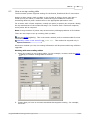
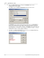
3.4
Converters
3.4.1
Introduction
A converter samples the output of sensors connected to it and gives these samples
numerical values. The numbers then go to the logger that is connected to the
converter.
Each converter has an address, which identifies it to the logger. Most converters are
supplied with the address set to 1. The Change converter address 33 program can
be used to change the address.
You can have up to 10 converters for each system using a mix of standard, humidity
or voltage converters.
3.4.2
EL001 temperature converter
The EL001 has three narrow sockets for sensors at one end. At the other end there
are two wide sockets for the network, and a red LED.
The LED flashes continuously immediately after the system is turned on. Once the
system is running normally, the light goes out and then flashes briefly each time the
converter takes a reading.
Each converter has an address - a number between 1 and 15 - that must be unique
on the network. The converter will already be programmed with an address, but you
can change this through the installation software.
When you install the system, the logging software will ask you for the address number
and where each of the three sensors are which relate to that converter address. For
large networks, it is best to make a plan of the layout before starting installation.
The three sensor sockets are marked with channel numbers.
emw.en
Copyright 2004-2008 Pico Technology Limited. All rights reserved.
Equipment
3.4.3
19
EL016 voltage converter
The EL016 voltage converter has eight voltage inputs. Each input can accept a
voltage in the range 0 V to 2.5 V.
The voltage inputs connect to the EL016 through a D9 female connector. The
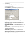
following table shows the pin connections and channel numbers for an EL016 with
address set to 1. 'A' will be address 1, 'B' will be address 2 and 'C' will be address 3.
Address
Channel
Pin
A
A
A
B
B
B
C
C
Ground
1
2
3
1
2
3
1
2
5
9
4
8
3
7
2
6
1
It is possible to display the voltages as other parameters - see the PSC file section of
the signal conditioner help file for more information.
3.4.4
EL026 temperature and humidity converter
The EL026 needs to be calibrated for a specific EL030. (Calibrating humidity
converters 34 )
Specifications
Humidity
Range
0 to 95% non-condensing*
Accuracy
±2.5% (0 to 90%)
Response time
Temperature
Enclosure
Vigorous Motion
~60 secs
Still Air
~60 mins
Range
0 to 70 °C
Accuracy
±0.2 °C
Dimensions
130 x 60 x 30 mm
Material
Black ABS
NOT waterproof
* capable of measuring over 90% humidity for short periods
Each EL026 converter has an address between 1 and 15. If you wish to connect more
than one converter to your logger, each converter must have a different address. If
you have two converters with the same address, install the software on your
computer and then use the Change converter address 33 program to change the
address of one of the converters.
The sensor must be situated away from direct contact with water and away from
sunlight. Temporary exposure to either is unlikely to damage the unit, but the unit
will give incorrect readings while it remains exposed.
Copyright 2004-2008 Pico Technology Limited. All rights reserved.
emw.en
20
EnviroMon User's Guide
The sensor can be attached to the wall either using adhesive foam, or by removing
the cover and using two screws to attach the unit to the wall.
3.4.5
EL037 voltage and 4-20mA converter
The EL037 has four inputs, and an external power input that can be used to supply
power (perhaps 12 or 24 V, depending on requirements) to the sensors.
Range
±2.5 V
±10 V
4-20 mA
15 bits + sign (40 µV per LSB)
15 bits + sign (0.15 mV per LSB)
15 bits (0.4 µA per LSB)
±0.3%
±0.5%
±0.4%
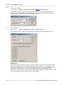
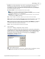
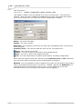
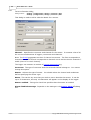
Each input can be configured using jumpers to accept either 2.5 V, 10 V or 4-20 mA.
It can be configured for other voltage ranges and for resistance measurement with
minor component changes. The following diagram shows how to set a jumper to
select the input type for a channel:
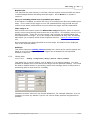
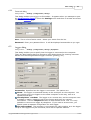
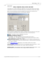
When measuring voltages, or for measuring 4-20 mA with the transmitter supplying
the loop current, the input is connected between IN and GND. The PWR connector can
be used to supply power to the transmitter:
When measuring 4-20 mA with the EL037 supplying loop current, the transmitter
should be connected like this:
emw.en
Copyright 2004-2008 Pico Technology Limited. All rights reserved.
Equipment
21
NOTE: only 100 mA is available for the whole network. When using the PWR
connector to supply power to the transmitter or to supply the loop current, it may be
necessary to use the external power input.
3.4.6
EL040 current monitor converter
The EL040 current monitor converter is intended for use with the TA011 current
clamp (details) 15 or similar current transformers that are designed for AC current
measurement.
The EL040 is a 3-channel device capable of monitoring three current transformers at
the same time (the current monitoring kit 30 comes complete with 3 current clamps).
Current transformers require no power and are available in a wide variety of formats,
from 200 A clamp-on units to 5000 A fixed-core transformers. These devices typically
generate an AC signal of 1 mV for each ampere flowing through a cable. The EL040
allows these currents to be easily measured using the EnviroMon system.
Specifications
Number of Channels
3
Sensor required
Max input voltage
TA011 current clamp or another suitable current
transformer
1 V AC RMS
Input impedance
> 1 MΩ
Frequency range
20 Hz to 1 kHz
Accuracy
±1% (0 to 200 mV)
±2.5% (200 mV to 1 V)
Operating temperature -20 °C to 70 °C
Input connector
4 mm banana plug
Connections
Most current transformers are fitted with 4 mm banana plugs, so that they are
suitable for use with multimeters. Connect the banana plugs on the current
transformer into the banana sockets on the EL040. The polarity is not important. The
current clamp should be clipped round a single core of the mains cable. It will not
give correct readings if live, neutral and earth wires all pass through the current
clamp.
Safety note: Current transformers are intended to simply clip round a
mains cable. It is not necessary to make an electrical connection to the
cable, and doing so may be dangerous. If you wish to work on uninsulated
high-voltage cables, please check the suitability of the current transformer
for this use.
Copyright 2004-2008 Pico Technology Limited. All rights reserved.
emw.en
22
3.4.7
EnviroMon User's Guide
EL041 thermocouple converter
The EL041 thermocouple converter is a 4-channel unit, intended for use with any
conventional thermocouple of type B, E, J, K, N, R, S or T with a 'mini-thermocouple'
connector. The EL041 is cold-junction-compensated for all types of thermocouple.
The compensation can also be switched off for measuring a ±60 mV input signal.
Specifications
Number of channels
4
Thermocouples supported
Voltage input range
B, E, J, K, N, R, S, T
SE0xx Thermocouples
±60 mV
Resolution
15 bits + sign bit
Accuracy
Conversion time
Thermocouples:
±(0.5 °C + 0.3% of type K reading)
Millivolts:
±0.3%
1 second
Overload protection
±10 V
Input connector
Mini-thermocouple plugs
PC connection
via EnviroMon network
Operating temperature
0 °C to 70 °C
(20 °C to 30 °C for quoted accuracy)
25 to 75% RH
Operating humidity
16
Note: The EL041 is designed to work only with the EL005 logger.
emw.en
Copyright 2004-2008 Pico Technology Limited. All rights reserved.
Equipment
3.5
Alarm devices
3.5.1
EL006 remote alarm
23
The EL006 remote alarm is useful when the room where the logger is located is not
often occupied. One or more remote alarms can be connected at any place along the
network where staff will hear the audible alarm.
The remote alarm looks like a standard converter, but has only the network sockets.
It is connected to the system using two network extension cables.
3.5.2
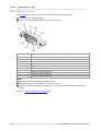
EL018 dialler adapter and battery backup
The EnviroMon system with the EL018 dialler adapter/ battery backup unit is designed
to operate with the Gardiner Technology Gardtec dialler or the Menvier Security SD1
speech dialler.
The dialler can be programmed with a list of emergency telephone numbers. When
there is a problem, the dialler calls each of the telephone numbers in turn until
someone answers, then it gives a message saying that there is a problem.
The dialler behaves in the same way as any normal extension and does not affect the
normal operation of the telephone.
The dialler adapter serves three purposes:
Controls the dialler
Provides power for the dialler and for the system
Is capable of providing battery backup for much longer periods than the logger's
internal backup
The dialler adapter is supplied in a grey plastic box with a clear lid. The box has a
large hole each side for cables. There is space for a 1.2 Ah battery, inside the box,
that will provide backup for 12 to 24 hours, depending on the configuration.
Alternatively the unit can be connected to a car battery, outside the box, that could
provide backup for many days.
Safety note: When using an 1.2 Ah battery inside the box, do not attempt
to seal the cable holes as this may cause an explosive build-up of gases
inside the box.
The speech dialler can give 3 different messages for 3 problem types as follows:
A - temperature out of range or sensor fail
B - mains (line power) fail for more than 2 minutes
C - network fail for more than 2 minutes
There is a separate wire between the adapter and the dialler for each problem. If you
do not wish to have calls made about a problem, leave the wire unconnected.
There are 3 red lights, one for each problem, that are turned on when the problem is
detected. There are 2 green lights: one for mains (line) power and one for battery
power. When the mains power is on, the battery is kept charged up continuously and
both the mains and the battery lights remain on.
Copyright 2004-2008 Pico Technology Limited. All rights reserved.
emw.en
24
EnviroMon User's Guide
There are 3 groups of screw terminals on the EL018 for the following purposes:
Backup battery
Speech dialler
Network (you can use the phone connector sockets if you prefer)
When using the EL018 with the EL005
EL005 and the EL018.
16
logger, plug a mains adapter into both the
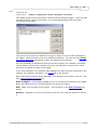
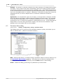
The connectors and lights on the EL018 are arranged as follows:
When it is wired into the system, it will look like this:
Similar products
EL042 alarm & relay unit
emw.en
25
Copyright 2004-2008 Pico Technology Limited. All rights reserved.
Equipment
3.5.3
25
EL042 alarm & relay unit
The EL042 alarm & relay unit has two modes of operation:
EL042 independent mode 27 . In this mode the unit provides three opto-isolated
switches and an audible alarm. It can also be used with the deviation alarms in the
EnviroMon software.
In this mode the unit can be powered from the network (which also recharges the
internal batteries). If the network power fails, the unit will continue to operate
from the batteries for several hours. This will allow already-activated alarm
conditions (activated before the network power failure) to be maintained. Alarms
cannot be set or cleared until the network is operating again.
A 12-volt supply is available to power external equipment up to a maximum of
30 mA (200 mA if the external 12-volt power adaptor is used).
EL018/EL006 emulation mode 26 . In this mode the unit can drive the
autodialler to provide one of three predefined messages depending upon the alarm
status.
In this mode we recommend that the unit is powered from the external 12-volt
power adaptor to provide sufficient power for the autodialler. Otherwise, the
network will power the autodialler but, depending upon the type of autodialler and
the number of converters on the network, there may be insufficient power on the
network. When the external power supply and network power both fail, the
batteries will provide power for the dialler for several hours.
LED status
When the unit powers up, the LED starts to flash. Once it has received a valid
message from the logger, the LED goes on continuously. If there is an alarm
condition, the LED flashes a number of times every five seconds to signal one of the
following alarm conditions:
flash – sensor alarm condition raised by logger
2 flashes – mains (line) fail; only if external mains adapter fitted
3 flashes – network failure
1
EL018 emulation
The EL042 can be programmed to emulate the EL018 dialler adapter/ battery backup
23 and EL006 remote alarm 23 units. See: Emulating the EL006 and EL018 29 .
Copyright 2004-2008 Pico Technology Limited. All rights reserved.
emw.en
26
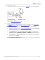
3.5.3.1
EnviroMon User's Guide
EL042 in EL018/EL006 emulation mode
The EnviroMon system with the EL042 25 in EL018 23 /EL006 emulation mode is
designed to operate with the Gardiner Technology Gardtec dialler or the Menvier
Security SD1 speech dialler.
The dialler can be programmed with a list of emergency telephone numbers. When
there is a problem, the dialler calls each of the telephone numbers in turn until
someone answers, then it gives a message saying that there is a problem.
The dialler behaves in the same way as any normal extension and does not affect the
normal operation of the telephone.
The dialler adapter serves three purposes:
Controls the dialler
Provides power for the dialler
Provides battery backup, if needed, for much longer periods than the logger's
internal backup
Safety note: The dialler adapter has a row of holes in the end of its case
for ventilation. Do not block these holes, as this could cause the unit to
overheat, leading to equipment damage or a fire.
There is a 4.8-volt rechargeable battery pack inside the box that will provide backup
for 12 to 24 hours, depending on the configuration.
The speech dialler can give three messages for different types of problem as follows:
A - temperature out of range or sensor fail
B - mains fail for more than 2 minutes
C - network fail for more than 2 minutes
There is a separate wire between the adapter and the dialler for each problem. If you
do not wish to have calls made about a problem, leave the wire unconnected.
The red lamp on the EL042 flashes once a second to indicate that the unit is
functioning.
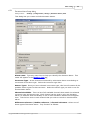
See also: Connector pin-out
28
.
When the EL042 is wired into the system, it will look like this:
emw.en
Copyright 2004-2008 Pico Technology Limited. All rights reserved.
Equipment
27
Alarm conditions
Sensor alarm. A sensor alarm activates Output A (see pinout 28 ) and the audible
alarm. This type of alarm is raised if the logger sends an ‘alarm on’ message. The
message will be repeated every sample interval. The alarm remains active until the
logger sends an ‘alarm off’ message. The alarm mode can be disabled by the logger.
Power supply fail alarm. A power supply fail alarm activates Output B (see pinout
28 ) and the audible alarm. This type of alarm is raised if the external 12-volt power
adaptor fails (due to a mains failure) for a given duration as set by the logger. The
alarm condition goes away immediately when the external power returns. The alarm
mode can be disabled by the logger.
Network fail alarm. A network fail alarm activates Output C (see pinout 28 ) and the
audible alarm. This type of alarm is raised if the unit does not receive a message
from the logger for a given duration as set by the logger. The alarm condition goes
away as soon as network communications return. The alarm mode can be disabled by
the logger.
3.5.3.2
EL042 in independent mode
In this mode the EL042 provides three opto-isolated switches (available from the
9-way D connector 28 ) and an audible alarm. It can also be used with the deviation
alarms in the EnviroMon software. This is the default mode of the EL042.
Alarm conditions
Audible and output alarms are controlled by messages sent from the logger. When
the logger is running on internal batteries (because of external power supply and
network power failure) alarms can only be maintained in their current state. They
cannot be set or cleared until the network is running again.
3.5.3.3
EL042 specifications
Specifications for the EL042 alarm & relay unit
25
Connectors
2 x network connector
1 x output connector
1 x power connector
Indicators
1 x red LED
Enclosure
Plastic case
Output connector
DE9M
See also: connector pin-out 28
Power connector
DC 1.3 mm
12 V unregulated input @ 200 mA max.
Positive on centre pin
External power adaptor
12 V unregulated @ 500 mA
EL042 power supply modes From external power supply, network or internal battery
Battery
NiCd module (as used in EL005 16 )
Compliance
CE (EMC)
Environmental
0 °C to 70 °C
10% to 90% humidity
not waterproof
Copyright 2004-2008 Pico Technology Limited. All rights reserved.
emw.en
28
3.5.3.4
EnviroMon User's Guide
EL042 connector pin-out
The EL042
25
's 9-way D connector provides the following outputs:
12 V power for speech dialler
Alarm (or speech dialler control) signals A, B and C
Pin number
Function
1
12 V dialler output (IOUT 200 mA max.)
2
3
4
5
6
7
8
9
Collector of opto-isolator C
Collector of opto-isolator B
Collector of opto-isolator A
Ground
N/C (do not use)
Emitter of opto-isolator C
Emitter of opto-isolator B
Emitter of opto-isolator A
Notes
Collector-emitter breakdown voltage is 30 V
Maximum continuous collector current is 150 mA
Emitter-collector breakdown voltage is 5 V at 100 µA (only applies if incorrectly
wired)
See also: EL042 example connection
emw.en
29
.
Copyright 2004-2008 Pico Technology Limited. All rights reserved.
Equipment
3.5.3.5
EL042 example connection
The following example shows how to connect the EL042
See also: EL042 connector pin-out
3.5.3.6
29
28
25
's opto-isolated Output A:
.
Switching to EL018/EL006 emulation mode
The EL042 25 can be reprogrammed to emulate a combination of the EL018 dialler
adapter/ battery backup 23 and the EL006 remote alarm 23 .
1.
Connect the EL042 to the data logger and disconnect all other converters.
2.
Referring to the procedure for Setting converter addresses
Converter Address program.
3.
Click the Read button. The program will show the address of the EL042 and
which mode it is in: Independent or EL018. An EL042 Independent Mode
check box will then appear in the program's main window.
4.
To set the EL042 to EL018 emulation mode, tick the check box, set the desired
address and click Program.
33
, start the Change
Use the Change Converter Address program again if you wish to switch the EL042
back to EL042 independent mode.
Copyright 2004-2008 Pico Technology Limited. All rights reserved.
emw.en
30
EnviroMon User's Guide
3.6
Package systems
3.6.1
Current monitoring kit
The current monitoring kit provides a complete solution for measuring three channels
of mains current. It could typically be used for measuring and balancing three-phase
supplies or monitoring the increase or decrease in current drawn from mechanical
equipment to aid maintenance schedules.
Kit contents
1 x EL005 data logger
1 x EL040 monitor converter
3 x TA011 current clamps
1 x EL003 sensor cable (5 m)
1 x power supply
PC software, cables and manuals
emw.en
Copyright 2004-2008 Pico Technology Limited. All rights reserved.
Getting started
4
Getting started
4.1
Installation of a package system
31
Connect the current monitoring kit together as follows:
1. Logger to PC. Connect the EL005 logger to either of the 9-pin D9 serial ports on
the computer using the serial cable.
2. Power. Plug the mains adapter into a mains socket and then plug the DC
connector into the logger. A red light should be illuminated on the unit to verify
power has been applied.
3. Network. Connect the EL040 current monitor converter to the EL005 data logger
using the EL003 network cable provided. Check that the red light on the converter
is flashing to signal a successful network connection. (More information on
networks 11 ).
4. Sensor. Attach the 4mm banana plugs from the TA011 current clamps
EL040 current monitor converter 21 .
15
to the
You are now ready to install the software, then configure the system. (More
information on installation 33 )
4.2
General installation instructions
4.2.1
Identifying the equipment
You will need the following equipment in order to set up a simple test system:
Computer
The computer must be running Windows XP (SP2) or Vista, and must have at least
one spare RS-232 or USB port. If you want to use a USB port, you will need a
USB-to-RS232 adapter available from Pico Technology, order code MI069.
RS-232 port
This is a D-shaped male (with pins sticking out) connector on the back of your
computer. The plug can have either 9 or 25 pins: if the plug has 25 pins, you will
need an adapter. Most computers have only two serial ports called COM1 and COM2.
The ports are not normally labelled, but it is usually safe to experiment to find out
which is which.
As mentioned above, if your computer does not have an RS-232 port, you can use a
USB port together with a Pico MI069 adapter.
Serial cable
This is a cream-coloured round cable about 2 metres long with a D-shaped 9-pin
connector at each end. The male end (the one with pins sticking out) connects to the
logger, and the female end attaches to the serial port on the computer.
Mains adapter
This is a black plastic block with a built-in mains plug. It has a black two-core cable
that goes to a round DC connector, which plugs into the power socket on the logger.
Copyright 2004-2008 Pico Technology Limited. All rights reserved.
emw.en
32
EnviroMon User's Guide
Logger
The logger collects data and stores it until the PC is ready to receive it. It has the
following connectors:
Round DC connector to mains adapter
D9 female connector to computer
Two square telephone-style connectors for network
The two network connectors are joined internally, so you can use either socket, or
both.
Network cable
This is a white oval cable about 5 metres long with telephone-style connectors at both
ends. Note that network connectors are slightly larger than sensor connectors.
Network connectors have six slots in the end, although only the middle four slots are
fitted with gold contacts.
Converter
The converter changes the electrical signal from a sensor into a digital message that
is transmitted to the logger. There are several types of converter, the most common
being the EL001 temperature converter. The EL001 is a plastic box with two square
network sockets at one end and three sensor sockets at the other end.
Each converter has a unique address between 1 and 15 that is used to identify the
converter.
Temperature sensor
The EL015 temperature sensor is a stainless steel tube, 6 mm in diameter and 50 mm
long. It is fitted with a white, oval cable about five metres long, with a
telephone-style connector on the other end.
The sensor connector is slightly smaller than the network connector. It has four small
slots, each containing a gold contact - unlike the network connector, which has an
empty slot at each end.
There is a clear plastic label on the cable next to the connector specifying the type of
sensor, the batch number and the sensor number. The batch number and serial
number are unique for each sensor, and can be used as a reference number for
calibration information.
Now go to Connecting up the equipment
4.2.2
32
.
Connecting up the equipment
To gain experience with the system, we recommend connecting up a small system,
with just a single converter, next to the computer. Once you are confident that you
understand how it works, you can install the complete system in the correct place.
1. Logger to PC. Connect the logger to either of the 9-pin D9 serial ports on the
computer using the serial cable.
2. Power. Plug the mains adapter into a mains socket and then plug the DC
connector into the logger.
3. Network. Plug one end of the network cable into the logger, then plug the other
end into one of the network sockets (labelled 'Net') on the converter.
4. Sensor. Plug the sensor into the first sensor socket on the converter.
Now go to installing the software
emw.en
33
.
Copyright 2004-2008 Pico Technology Limited. All rights reserved.
Getting started
4.2.3
33
Installing the software
Installing under Windows XP (SP2) or Vista:
1.
2.
3.
4.
5.
6.
7.
Insert the Pico CD into your CD-ROM drive
If Autorun is enabled, the CD will startup automatically. If so, go to step 5.
Click the Start button and select Run...
Type d:\pico (where 'd:' is your CD-ROM drive)
Press the Enter key
Click the Install Software button
The program will guide you through the installation
To run the software:
1.
2.
3.
4.
4.2.4
Click the Start button
Select Programs
Select Pico Technology
Select EnviroMon
Setting converter addresses
Note: You can skip this section if you have only one converter; for example, if you are
using a starter kit.
If you are planning to use more than one converter, each converter must have a
different address. If you have two converters with the same address, you must
change the converter addresses so that each converter has a unique address BEFORE
you connect up the complete network. To do this:
1.
2.
3.
4.
5.
6.
7.
8.
9.
10.
11.
12.
13.
14.
15.
16.
Install the software on your computer
Connect the logger to a serial port on the computer using the cable provided
Plug the power supply into the mains and connect it to the logger
Connect the first converter to the logger using the network cable
Click the Windows Start button
Select Programs
Select Pico Technology
Select Change Converter Address
Select the serial port (e.g. COM2) to which you connected the logger
Select the address that you wish to use for this converter
Click the Program button
Wait until the computer reports that the converter has been programmed
For EL026 humidity converters, see Calibrating humidity converters 34
For EL042 25 alarm/dialler adaptor units, see Emulating the EL018 29
Unplug the converter
Repeat this procedure for each converter
Copyright 2004-2008 Pico Technology Limited. All rights reserved.
emw.en
34
4.2.5
EnviroMon User's Guide
Calibrating humidity converters
If you are not using humidity converters, you can skip this section.
The EnviroMon humidity measuring system is made up of two parts: the EL026
converter 19 and the EL030 sensor 15 . These can be connected together using a
cable up to 25 metres long.
The EL030 sensor has some calibration information written on the base. Before you
use an EL026 and EL030 together, you should use the Change Converter Address
program to write this calibration information into the EL026.
To do this, connect up the equipment and run the Change Converter Address
program according to the instructions for setting the converter address. Then
proceed as follows:
1.
2.
3.
4.
5.
6.
7.
8.
9.
10.
4.2.6
Select the serial port to which you have connected the logger (e.g. COM2)
Select the address that you wish to use for this converter
Click the Program button
Wait until the computer reports that the converter has been programmed
The computer will turn on the Calibration button. Click this button now.
Enter the lowest figure (normally about 0%) into the first box
Enter the highest figure (normally about 100%) into the second box
Click the Program button
Wait until the computer reports that the converter has been programmed
Unplug the converter
Configuring the system
To run the software:
1.
2.
3.
4.
Click the Start button
Select Programs
Select Pico Technology
Select EnviroMon
The first time you start up the software, it will offer you three choices:
1. A look at the overview section of the help file
2. A guided tour of the configuration
3. Start the configuration
If you select the guided tour, the computer will take you through the basics of setting
up the system, explaining what each step involves. Alternatively, you can follow the
instructions below.
If you are not already in the Configuration control panel:
1. Select Settings from the main menu
2. Select Configuration from the Settings menu
3. Select Change
You should now be at the Configuration control panel. If you have already
configured the system and wish to start again:
1. Click Reset
2. When the computer asks you to confirm, click Clear
emw.en
Copyright 2004-2008 Pico Technology Limited. All rights reserved.
Getting started
35
Once you are back at the Configuration control panel, it is time to set the sampling
rate:
1.
2.
3.
4.
5.
Click General
Click Sampling
Set the Minutes per Reading field to the required value
Click OK
Click OK
Now find out what equipment is connected:
1.
2.
3.
4.
5.
Click Equipment
Set the serial port field to the one to which the logger is connected (such as COM2)
Click Converters
Click Auto-configure
A box will appear and will show you the status of the auto-configure process. After
a few seconds, this will disappear and the computer should display the details of
your converter in the large box.
6. Click OK
7. Click OK
Now to specify where the sensors are to be located, by giving names to them:
1.
2.
3.
4.
5.
6.
Click Locations
Click Add
Type in a name for your sensor in the Name field
Select the channel that you wish to use (channel 1 on your converter)
Select the type of sensor, for example EL015.
Click OK
If you are planning on using the current monitoring kit, select EL040 - Amps as the
sensor type.
Now you need to program the calibration information into the logger.
1. Click Program
2. A box will appear and will show you the status of the auto-configure process. After
a few seconds, this will disappear if the programming completed successfully.
The configuration is complete. You must exit the program now so that the changes
will take effect:
1. Click Exit
2. Click OK
You will need to restart the software to display the readings.
Copyright 2004-2008 Pico Technology Limited. All rights reserved.
emw.en
36
4.2.7
EnviroMon User's Guide
Looking at current readings
To look at the current readings, start the EnviroMon program:
1.
2.
3.
4.
Click the Start button
Select Programs
Select Pico Technology
Select EnviroMon
If it is more than a few minutes since you last ran the software, the computer will
display a box to show you how many readings it has transferred from the logger.
The computer next displays the Monitor window
sensor.
39
- a list of temperatures for each
When the monitor window is active, you may find the following features useful:
Select Settings, then Configuration, then Change to make changes to the
configuration
Select View... then another option to view stored data
Select Help then Contents to get the help file contents page
Select Help then Index to get an index for the help file
Select Help then Guided tour for a guided tour of the functions used in
day-to-day operation
4.2.8
Displaying a graph
To look at the graph, you first need to display the Monitor window
39
.
Next, take the following steps:
1. Select View from the main menu
2. Select Graph from the View menu
The computer will display a graph showing all data recorded so far.
emw.en
Copyright 2004-2008 Pico Technology Limited. All rights reserved.
Getting started
4.2.9
37
Saving and restoring configurations and data
The Settings menu contains commands for saving and restoring your EnviroMon
configurations. You can work with either EnviroMon configuration (.emwcfg) files or
EnviroMon archive (.emwarc) files.
Change. Opens the Configuration control panel
settings.
47
, from where you can modify all
Save As Default. Saves the current EnviroMon configuration, which you can later
retrieve using Load Default.
Load Default. Loads the EnviroMon configuration that was last saved using Save As
Default.
New. Clears all configuration information. If you wish to retain the present
configuration, ensure that you save it before selecting this command.
Open. Opens a selected .emwcfg file containing an EnviroMon configuration.
Save As. Saves the current EnviroMon configuration in a named .emwcfg file.
Open Archive. Opens a selected .emwarc archive file.
Save As Archive. Creates an .emwarc archive file containing the EnviroMon
configuration, logged data, the event log, and user scaling data. For an example of
when to use archive files, see How to use multiple loggers 79 .
Copyright 2004-2008 Pico Technology Limited. All rights reserved.
emw.en
38
5
EnviroMon User's Guide
Display options
EnviroMon can display data in five different formats, corresponding to the following
five window types:
Monitor window 39 . Shows current temperatures and alarm state
Graph window 41 . Shows the temperature over a period of time
Summary window 43 . Shows the statistics and error information for a period of
time
Spreadsheet window 44 . Shows detailed temperature information in a format
that can be copied to a clipboard
Event window 46 . Shows each of the occasions on which an out-of-range or
sensor fail has occurred
The monitor window is displayed when you start the program. The other windows can
be selected from the View menu.
emw.en
Copyright 2004-2008 Pico Technology Limited. All rights reserved.
Display options
5.1
39
Monitor window
When you start EnviroMon, the computer displays the Monitor window, which looks
like this:
The window has a menu that gives access to other windows, and a line of information
for each active sensor.
At the left of each line is an indicator lamp, whose colour shows the state of the
sensor:
Sensor value is within range.
Sensor value is currently out of range, but has not been out of range long
enough to raise an alarm.
Sensor is in an alarm state. Double-click the lamp to cancel the alarm.
Sensor is an alarm state, but the alarm has been cancelled.
Next to each lamp is the sensor name and the current temperature. The temperature
is updated every few seconds.
The Monitor window has a menu, which you can use to:
select which sensors appear on the monitor window
activate other windows
configure the system
specify various options, including colour and sound
When the Monitor window is running, you can find out about the menu by pointing
at a menu option and pressing the F1 key.
If you minimise the monitor window, the computer will display an EnviroMon icon
alternating with a status lamp that shows whether there are any warnings or alarms:
If an alarm occurs, you can then click the icon to restore the Monitor window.
If you have set up one or more deviation alarms, the monitor window will contain
extra information: see Monitor window with deviation alarms 40 .
Copyright 2004-2008 Pico Technology Limited. All rights reserved.
emw.en
40
5.2
EnviroMon User's Guide
Monitor window with deviation alarms
If you have set up deviation alarms, the Monitor window 39 will display one or
two extra columns of status lamps. The example below shows a simple setup with
one deviation alarm:
In this example, the monitor window shows that a deviation alarm called "Deviation 1"
has been set up for the Ch 6.1, Ch 6.2 and Ch 6.3 sensors. The deviation alarm has
its own status lamp, in addition to the lamps for the individual sensors.
See also
Nested deviation alarms 71 , for a more complex example
How to set up a deviation alarm 86 , for a detailed procedure
emw.en
Copyright 2004-2008 Pico Technology Limited. All rights reserved.
Display options
5.3
41
Graph window
When you select Graph from the View menu, the computer opens a new window like
this:
If you move the mouse cursor onto the graph part of the screen, the computer will
display the temperature and time at the current cursor position.
There are a number of buttons in the top right of the screen. The horizontal row of
buttons selects what time interval is displayed:
- Scroll left. Moves to the left by a whole display (earlier)
- Scroll quarter left. Moves a quarter display left (earlier)
- Expand horizontal axis. Magnifies the middle half of the display to fill the whole
width
- Shrink vertical axis. Shrinks the current display to half size, so that more is
displayed before and after
- Scroll quarter right. Moves a quarter display right (later)
- Scroll right. Moves a whole display right (later)
The upper group in the vertical column of buttons controls the vertical range
displayed. Note that if you use these controls to change the vertical range,
auto-scaling is turned off. Use the options button (see below) to turn auto-scaling
back on again.
- Scroll up. Moves a whole display up.
- Expand vertical axis. Magnifies the middle half of the display to fill the whole
height.
- Shrink vertical axis. Shrinks the current display height to half size, so that
more is displayed above and below.
- Scroll down. Moves a whole display down.
The remaining controls in the vertical column are:
- Select today. Sets the time axis to run from midnight yesterday to midnight
today.
Copyright 2004-2008 Pico Technology Limited. All rights reserved.
emw.en
42
EnviroMon User's Guide
- Select this week. Sets the time axis to run from the first to the last day of this
week. By default, the first day of the week is Monday. The FirstDayOfWeek 110
preference can be used to specify a different day.
- Copy to clipboard. Copies the graph to the clipboard.
- Print contents of window. Prints the graph.
- Select channels. Selects the channels to display on the graph.
- Window options. Specifies the options for the graph.
- Help. Goes straight to help information specific to the graph window.
Axis control buttons
5.3.1
42
Axis control buttons
The axis control buttons appear in the Graph window
41
.
Vertical axis control button. Opens a text box in which you can type the
maximum and minimum values for the vertical axis. These must be within the
range of acceptable values for the sensor. Click the button to apply the values
and close the text box.
Horizontal axis control button. Opens a text box in which you can type the
scale of the horizontal (time) axis. You can also use the up and down spin
buttons to change the value. The time can be set in hours or days, or a
combination of both. Click the button to apply the values and close the text
box.
emw.en
Copyright 2004-2008 Pico Technology Limited. All rights reserved.
Display options
5.4
43
Summary window
When you select Summary from the View menu, the computer opens a new window
like this:
The Period section of the window contains the time interval to which the summary
applies. You can either type in a start and end time and date, or use the buttons to
alter the range. The controls are as follows:
-
Earlier. Moves a quarter period earlier.
Expand horizontal axis. Halves the current period.
Shrink horizontal axis. Uses twice the current period.
Later. Moves a quarter period later.
The Sensor area of the window shows which sensor is to be displayed in the
summary. If you select a different sensor, the display will be updated.
- Print contents of window. Prints a summary for all sensors for the current
period.
- Help. Goes straight to help information specific to the graph window.
The Statistics section of the window shows the number of readings during the period
for this parameter, and the minimum, maximum and average for the period.
If the readings go out of range during the period, the computer displays a separate
figure for the average of the in-range values (it excludes the values that are out of
range from the average calculation). This is useful if the parameter goes out of range
only under known circumstances, such as during a defrost cycle on a chiller. The
in-range average appears in brackets on the printed report.
The Problems section of the window shows the number of times and total time the
value has been out of range. There are separate figures for above range, below range
and sensor fail.
Copyright 2004-2008 Pico Technology Limited. All rights reserved.
emw.en
44
5.5
EnviroMon User's Guide
Spreadsheet window
When you select Spreadsheet from the View menu, the computer opens a new
window like this:
There is one line for each reading. The first two columns show the time and date, and
the remaining columns show the selected sensors. The scroll bar on the right selects
the range of times to display.
If you select a range of readings, you can use the following buttons:
- Write to disk. Writes the readings to a disk file.
- Copy to clipboard. Writes the readings to the clipboard.
The following options buttons are available:
- Print contents of window. Prints out a summary for all sensors for the current
period.
- Window options. Here you can specify whether to display individual readings,
or average, minimum and maximum for a period.
- Select channels. Opens the Select parameters 74 dialog box.
- Select today
- Select this week
- Earlier. Move a quarter period earlier.
- Later. Move a quarter period later.
- Help. Go straight to help information specific to the spreadsheet window.
You can select a range in one of three ways.
If all of the readings that you want to select are on the screen:
1. Point the mouse at the first reading
2. Click and hold down the left mouse button
3. Drag the mouse to the last reading, and the selected readings will be highlighted as
you go
4. Release the left mouse button
emw.en
Copyright 2004-2008 Pico Technology Limited. All rights reserved.
Display options
45
If the readings are a long way apart:
1.
2.
3.
4.
5.
Point the mouse at first reading
Click the left mouse button, and the first reading will be highlighted
Scroll down to the last reading
Point at the last reading
Press the Shift key and click the left mouse button
If you wish to select all of the readings for one day:
1. Point the mouse at any reading during the required day
2. Click the left mouse button, and the reading will be highlighted
3. Click the
button
Copyright 2004-2008 Pico Technology Limited. All rights reserved.
emw.en
46
5.6
EnviroMon User's Guide
Events window
When you select Events from the View menu, the computer opens a new window
like this:
There are two or four lines of text for each event. At the left are the start and end
date/time, although the end date/time is omitted if the fault is still active. Next to
these are the sensor name and a description of the fault. If Show action taken is
enabled, the action taken will be displayed beneath the fault description.
The scroll bar on the right selects the range of times to display.
To select a range of readings, you can use the following buttons:
-
Write to disk. Writes the events to a file on disk.
Copy to clipboard. Writes the events to the clipboard.
Print the contents of window. Prints the events.
Window options. Specifies the options for the events.
Help. Goes straight to help information specific to the events window.
You can select a range in one of two ways.
If all of the readings that you want to select are on the screen:
1. Point the mouse at the first event
2. Press and hold the left mouse button
3. Drag the mouse to the last event, and the selected events will be highlighted as
you go
4. Release the left mouse button
If the events are a long way apart:
1.
2.
3.
4.
5.
Point the mouse at the first event
Click the left mouse button, and the first event will be highlighted
Scroll down to the last event
Point at the last event
Press down the Shift key and click the left mouse button
To edit the notes on action taken for an event, double-click the event.
emw.en
Copyright 2004-2008 Pico Technology Limited. All rights reserved.
Main settings
6
47
Main settings
Dialog location:
Settings | Configuration | Change
The Configuration control panel is the main interface for configuring the system.
For a first-time installation, use each of the buttons in the sequence that they appear.
If you later wish to make adjustments to the system, you can go straight to the
function that you wish to change, then use the Program button to write the new
configuration to the logger.
Note: before you use the Program button or the Auto-configure button in the
Converters dialog box (part of Loggers), the logger must be connected.
This button leads to the General configuration info 48 panel. There
are buttons to set the sampling interval, temperature units and other
system-wide parameters.
This button opens the User List 55 dialog. It is necessary only if you
wish to restrict access to the configuration dialogs. Its purpose is to
help you define a list of people authorised to use the system.
This button works in two modes. In a system with a single data logger,
it displays the Logger 57 dialog, allowing you to specify how the logger
is connected to the computer. There are also buttons to enter converter
information, and details about more advanced logger functions (logger
printer, reporting, alarm dialler etc.) In a system with multiple data
loggers, it displays the Logger list 64 dialog, allowing you to add or edit
details for a number of loggers.
This button displays the Sensor list 65 dialog. As well as displaying a
list of the sensors currently in use, it provides options to add or edit
sensors. The sensor information includes the sensor name, its address
(logger, converter, channel) and its alarm limits.
This button opens the Deviation Alarm 68 dialog, which allows you to
set up alarms based on the differences between channels.
This button writes the configuration information to the logger. The
process is automatic: just plug in the logger, then click the button and
wait for it to complete.
Copyright 2004-2008 Pico Technology Limited. All rights reserved.
emw.en
48
6.1
EnviroMon User's Guide
General configuration info panel
Dialog location:
Settings | Configuration | Change | General
The General configuration info panel allows you to control the system parameters
that are not related to a specific logger or sensor.
Opens the Sampling interval
between recorded readings.
49
dialog, which sets the time interval
Opens the Temperature display 50 dialog, which selects the units
and number of decimal places for temperature measurements.
Opens the Alarm behaviour 50 dialog, which specifies options (time
ranges, repeat interval, etc.) for alarm handling.
Opens the Site information 52 dialog, which accepts a site name and
contact details for maintenance.
Opens the Summer time dates 52 dialog, which sets the dates for the
start and end of summer time. The logger can then automatically put
its clock forward or back at the right time.
Opens the Data storage 53 dialog, which accepts directory names for
data and backup files, and controls the cleaning-up of old data files.
Note: changes to the general settings are saved when you click the OK
button. If you click the Cancel button, any changes are discarded.
Opens the Scale
files for sensors.
emw.en
54
dialog, which allows you to create and edit scaling
Copyright 2004-2008 Pico Technology Limited. All rights reserved.
Main settings
6.1.1
49
Sampling interval dialog
Dialog location:
Settings | Configuration | Change | General | Sampling
This dialog is used to specify when readings are to be recorded.
Start sampling
Leave this set to Immediate. Other options are for specialist use only.
Minutes per reading
This is time interval between recorded readings in the logger. The logger measures
and displays values from sensors continuously, and then stores the average value at
the intervals specified.
Mode
This defines whether to fill the whole of the logger memory with readings and, if so,
whether to stop when the logger is full. There are three options, as follows:
Wrap when full. When the logger memory is full, it starts overwriting the oldest
readings. This is the correct option when you wish to collect data continuously for
long periods, as the logger will then contain the most recent readings at any time.
Stop when full. The logger stops saving readings as soon as its memory is full.
This is useful if you wish to make sure that you do not lose the readings taken
immediately after you start the logger, even if you do not download the information
regularly.
Stop after n samples. The same as Stop when full, but the No of samples
field below defines the number of readings to collect before stopping.
Note: If you use Stop when full or Stop after n samples modes, you can restart
the logger only by disconnecting and reconnecting the mains adapter and battery
from the logger, or by reprogramming it.
No of samples
This specifies the number of readings to collect before stopping when in Stop after n
samples mode.
Copyright 2004-2008 Pico Technology Limited. All rights reserved.
emw.en
50
6.1.2
EnviroMon User's Guide
Temperature display
Dialog location:
Settings | Configuration | Change | General
48
| Temperature
This dialog is used to specify the units for temperature measurements and the
number of decimal places for measurements. Readings are normally displayed in
Celsius with two decimal places, for example 4.65 °C.
6.1.3
Alarm behaviour
Dialog location:
Settings | Configuration | Change | General | Alarm
This dialog is used to specify the way alarms should be handled by the system.
Hysteresis
If a temperature goes out of range, it must go back in range by at least this much
before the logger considers that the problem has gone away. For example, if the
maximum temperature is 15 °C and the hysteresis is 0.5 °C, the temperature must
drop to 14.5 °C before the problem is considered to have gone away. If the
temperature drops below 15 °C but then goes above it again, this will not be treated
as a new problem and the alarm will not sound again.
emw.en
Copyright 2004-2008 Pico Technology Limited. All rights reserved.
Main settings
51
Repeat time
This specifies the time interval, in minutes, that the system must wait after an alarm
is acknowledged before activating the alarm again. Set to None if no repeat is
required.
Carry on sounding alarm even if problem goes away...
If this option is enabled, the alarm will carry on sounding even after the problem goes
away. This is useful if the logger is to be left unattended for long periods and you
need to know about problems that occurred while the logger was left unattended.
Time range 1..6
Each of these six buttons opens the Alarm time range dialog box, which is used to
specify a time range during which alarms are to be active - for example, 09:00-17:00
Monday to Friday. There are six time ranges, and a sensor can be associated with
any combination of ranges. If you are using an EL042 alarm & relay unit, this dialog
also allows you to specify which EL042 outputs are active. (More on sensor alarms)
67
Once the details have been specified for a time range, the details will be displayed
next to the relevant button.
Holidays
This button opens the Holiday dates 51 dialog box, which can be used to specify the
dates of up to 12 holidays. Alarm time ranges can be disabled on the specified
holidays if required.
6.1.4
Holiday dates
Dialog location:
Settings | Configuration | Change | General | Alarm | Holidays
This dialog box is used to specify a list of dates of up to twelve holidays. It is then
possible to disable some or all alarm time ranges on the specified holidays. This could
be used to disable sensors in processing (rather than storage) areas on days when a
processing plant is shut down for a holiday.
The dates must be entered in the format DDMmmYY, for example 25Dec08. It is not
necessary to enter any details if you do not need to make special arrangements for
holidays.
Copyright 2004-2008 Pico Technology Limited. All rights reserved.
emw.en
52
6.1.5
EnviroMon User's Guide
Site information
Dialog location:
Settings | Configuration | Change | General | Site
This dialog is used to specify the site name and maintenance contact. This information
appears on reports printed by the computer or by the logger.
Name of site. The name of the site where the loggers are to be installed.
Maintenance contact. Contact details for maintenance calls. For example, in a
freezer monitoring application, this might be the the name and telephone number of
the refrigeration engineer.
6.1.6
Summer time dates
Dialog location:
Settings | Configuration | Change | General | Summer time
In countries that are a long way from the equator, it is normal to adjust the clocks by
one hour at the start and end of summer. This has different names in different
countries: for example, daylight saving time, or British Summer Time.
You can enter the start and end times for summer time for the next few years, and
then the logger will automatically adjust its clock on the specified days.
Note: in the Northern hemisphere, the start and end times will be in pairs, each pair
for the same year. In the Southern hemisphere, the start of summer will be in
October of one year and the end of summer will be in March of the following year.
emw.en
Copyright 2004-2008 Pico Technology Limited. All rights reserved.
Main settings
6.1.7
53
Data storage
Dialog location:
Settings | Configuration | Change | General | Directories
This dialog is used to set the directory names for data files and backup.
Data file cleanup. This option can be used to clean up old data files when they are
no longer required. The options are:
Keep data files indefinitely
Delete after one month
Delete after three months
Delete after a year
Automatic backup. If this option is checked, the program automatically does a
backup when you exit from the program. This is probably more suitable for backup to
a network drive than for backup to a diskette. If this option is not checked, you can
still do backups using the Backup option on the File menu.
Directory for data files: leave blank for normal setup. This is a handy feature if
you want to save the file containing the data somewhere different (for example, on a
network drive so that it can be backed up more easily) or if you wish to operate
several loggers independently, each with their own data files. For most applications,
it can be left blank, and the file containing the data will be stored in the same
directory as the EnviroMon program. To specify that data files should be stored on
network drive G: in a directory called Pico, type in G:.
Backup directory. This is where files will be copied when a backup takes place. This
could be either a diskette drive or a network directory. If you specify a diskette drive,
the computer asks you to insert a blank, formatted diskette before each backup.
Copyright 2004-2008 Pico Technology Limited. All rights reserved.
emw.en
54
6.1.8
EnviroMon User's Guide
Scale
Dialog location:
Settings | Configuration | Change | General | Scale
The Scale dialog is the easiest method for creating scaling look-up tables. (Overview
of scaling tables) 81
Name. The name of the scaling method. The same scaling method could be used for
multiple sensors (in this case, for example, the pressure from a number of different
sensors of this type).
Conditioner. The type of conditioner that the sensor will work with. If this sensor
does not require a signal conditioner, set the conditioner type to 'None'.
Sensor. A unique reference for this scaling method. EnviroMon fills in this field for
you.
Units. The units appear next to the parameter value on graphs, reports etc.
OutOfRange. Specifies what to do if the raw value is outside the range of the table
lookup. The options are:
treat as a sensor failure
clip the value to the minimum or maximum table value
extrapolate the value using the nearest two table entries
Places. The number of decimal places. With 1 decimal place, the value 15 would be
displayed as 15.0. With 2 decimal places, same number would appear as 15.00.
Method. The scaling method. This is always 0 (table lookup method).
emw.en
Copyright 2004-2008 Pico Technology Limited. All rights reserved.
Main settings
55
On/Off. For numeric parameters, set to 'Off'. For parameters that can have only
two values (on or off), set to 'On'. Then set the scaling table so that Raw=0
corresponds to Scaled=0, and Raw=1 corresponds to Scaled=100. The logger will
then display 'On' or 'Off' for the parameter, and reports will show the percentage of
time that the parameter was 'On'.
No, Raw, Scaled. Column headings for the look-up table.
No is the row number, supplied automatically by EnviroMon.
Raw is the raw value from the sensor, normally in millivolts, but for the CM007
(4-20mA) conditioner, it is in milliamperes.
Scaled is the scaled value corresponding to each raw value. It is in the units
specified by the Units parameter.
New. Clears all data in the table, ready for you to enter a new set of data.
Open. Shows a list of all scaling tables that you have previously stored. If you select
one of these, it will be copied into the Scale dialog for you to examine or edit.
Save. Saves the present scaling data using the name in the Name box. Remember
to change this name if you wish to create a new scaling table; otherwise you will
overwrite the table that was previously opened.
Close. Close the dialog without saving the scale data.
6.2
User list dialog
Dialog location:
Settings | Configuration | Change | Security
This dialog shows details for each of the users who are, or have been, authorised to
use the system. An 'x' next to the name indicates that they are no longer active. You
can add new users or edit the details of existing users. It is not usually necessary to
specify users if only one person will be using the system. If you do add any users,
the computer will ask for a password if you attempt to use the Settings |
Configuration | Change command.
Add. Click to add a new user.
Edit. Click one of the names in the user list. When the name is highlighted, clicking
the Edit button will enable you to edit the details for the selected user.
Copyright 2004-2008 Pico Technology Limited. All rights reserved.
emw.en
56
6.2.1
EnviroMon User's Guide
User information
Dialog location:
Settings | Configuration | Change | Security | Add
This dialog is used to enter the details for a new or existing user. This process is
optional. After you have created and enabled the first user, EnviroMon will require
you to log in before you can make any further configuration changes.
Name. The user's full name.
Initials. The user's initials.
Password. The computer will ask for this each time somebody enters a secure part
of the program.
Clearance level. This controls what the user can do. The options are:
None. The user has no access.
Check. The user is able to check the current temperatures.
Note. The user is able to edit details of events.
Full. The user has access to all parts of the system, including configuration.
Note: when you add the first user, always set the Clearance level to Full, otherwise
you will not be able to get back into the configuration to change it.
Enabled. It is not possible to remove details of old users, as the system may need to
refer to their data at some point in the future. Instead, uncheck the Enabled box to
remove the person from the list of active users. If you disable all users, then
EnviroMon will let you reconfigure the system without logging in.
emw.en
Copyright 2004-2008 Pico Technology Limited. All rights reserved.
Main settings
6.2.2
57
Password dialog
Dialog location:
Settings | Configuration | Change
This dialog enables you to log in to EnviroMon. It appears when you attempt to open
the Configuration panel 47 from the Settings menu and there is at least one active
user in the User list 55 .
User. This is a list of active users. Select your name from the list.
Password. Enter your password here. It will be displayed as asterisks as you type.
6.3
Logger dialog
Dialog location:
Settings | Configuration | Change | Equipment
This dialog enables you to specify how the logger is connected to the computer.
There are also buttons that give access to other dialog boxes for entering converter
details and controlling advanced logger functions (printing, etc.)
Connection. Specifies how the logger is connected. The options are:
Direct. The logger is connected directly to the serial port on the computer. You
can connect up to nine loggers to the same computer in this way, each to a
separate serial port.
Via telephone + modem. The logger is at a remote site, and the computer uses
a modem to make a telephone call to the logger each time you request
information. Use the Telephone button to enter details of the link. It is only
possible to connect one logger by telephone. If you need to access more, you
should create a separate configuration for each logger.
Via radio modem. The computer is connected to a radio modem, as is the logger.
Up to 250 loggers may be connected, each with a separate address.
Copyright 2004-2008 Pico Technology Limited. All rights reserved.
emw.en
58
EnviroMon User's Guide
Note: Loggers are supplied programmed for direct connection at 9600 baud. If you
change the baud rate option or you wish to use a telephone modem, you should use
the Set Link option (see below) to write the link parameters into the logger.
Serial port. Selects which COM port is to be used.
Address. Used on a multi-logger radio link. Each logger has a unique address
between 1 and 255. All loggers receive all messages from the computer, but only
respond to messages containing their address.
Baud rate. Specifies the data rate to use for the link to the logger. For a direct link
over a short cable, use 57600 baud. For a modem, check the maximum speed that
the modem can handle. Most modern telephone modems can operate at 57600 baud
to the logger, even if they operate at a lower speed over the telephone link.
Enable support for multiple loggers. If you check this box, the computer replaces
this dialog box with the Logger list 64 dialog, with which you can add, edit or remove
the details for loggers.
Most systems require only a single logger, so the computer normally only presents a
dialog box for a single logger. Even if you wish to use multiple loggers, it may be
more practical to set up a separate configuration for each logger. That way, the data
for each logger is kept separate. This option is only useful if you wish to combine the
data from multiple loggers.
Converters. Opens the Converter list
converters attached to the logger.
59
dialog box which provides a list of all the
Options. Opens the Logger Options 61 dialog box which controls optional
equipment that can be connected directly to the logger.
Telephone. Opens the Logger dialup options 62 dialog box which enables you to
specify how the dial-up link to the logger is to operate.
Set link. Programs the connection settings into the logger. Loggers are supplied
ready-configured for direct connection to the computer, so you do not need to use
this option for loggers intended for direct connection. You use this button only when
you have changed the connection mode. Connect the logger directly to the port that
you have specified, then click the button and wait for it to complete. The
programming is automatic.
Note: The logger must be powered down and restarted to activate the new link
parameters.
Diagnostics. Opens the Network diagnostics 63 dialog. Do not use this option
unless directed to do so by Pico Technical Support staff.
emw.en
Copyright 2004-2008 Pico Technology Limited. All rights reserved.
Main settings
6.3.1
59
Converter list
Dialog location:
Settings | Configuration | Change | Equipment | Converters
This dialog shows a list of converters connected to the selected logger. There are also
controls to add or remove converters, or to automatically detect the converters
connected to the logger.
The converter list shows the address and type of each of the converters attached to
the logger. Each converter must have a different address. You can use the Change
Converter Address 33 program to alter the address of a converter.
It is not necessary to add devices that do not have sensors (for example, the EL006
remote alarm), but the auto-configure function will add them to the list as a check
that they are linked correctly to the logger.
If you auto-configure, the computer also displays any alarm devices connected to the
network (for example, the EL016, the EL018 23 , or the EL042).
Note: Each EL016 requires three addresses, so it appears three times in the list. See
also: EL016 voltage converter 19 .
Auto-configure. Automatically update the list of converters connected to the logger.
Note: the logger must be connected before you select this option.
Add. Add a new converter to the logger. This will open up the Add converter
dialog.
60
Remove. Highlight one of the converters in the list, then click this button to remove
it.
Copyright 2004-2008 Pico Technology Limited. All rights reserved.
emw.en
60
6.3.2
EnviroMon User's Guide
Add converter
Dialog location:
Settings | Configuration | Change | Equipment | Converters | Add
This dialog is used to enter the details for a new converter.
Type. The converter type.
Address. Each converter connected to the logger must have a different address. If
you have two converters with the same address, you should use the Change
converter address 33 program to change the address of one of the converters.
If you make a mistake and enter the same converter twice, the computer will warn
you when you try to program the logger.
emw.en
Copyright 2004-2008 Pico Technology Limited. All rights reserved.
Main settings
6.3.3
61
Logger options
Dialog location:
Settings | Configuration | Change | Equipment | Options
This dialog contains controls for optional equipment connected to the logger.
Alarm dialler. The logger can be connected to a dialler unit so that, when an alarm
occurs, the dialler calls a specified number and delivers a recorded message. The
dialler connects to the logger using an EL018 or EL042 dialler interface. In addition to
providing a link to the dialler, the EL018 and EL042 provide the following functions:
A larger backup battery, with mains charger
Detection of mains failure
Detection of network failure (the logger is no longer in contact with the EL018 or
EL042)
On detection of mains or network failure, the interface can be programmed to activate
the alarm dialler after a specified period of time. (Additional information on the EL018
23 and EL042) 25
Battery operation. With the EL005 logger, it is possible to specify what functions
are to carry on if the mains power fails, in order to conserve battery power.
The sampling can be set as follows:
Constant. All the time, even during mains fail.
Reduced. At a reduced rate (only one reading for every sample interval).
Stopped. Stop taking readings.
The serial port can be set as follows:
Constant
Only if DTR
Off
Copyright 2004-2008 Pico Technology Limited. All rights reserved.
emw.en
62
6.3.4
EnviroMon User's Guide
Logger dial-up options
Dialog location:
Settings | Configuration | Change | Equipment | Telephone
This dialog enables you to specify the details of:
1 Connection to logger (routine download)
2 Connection from logger (on alarm)
Note: The Telephone button is greyed out unless the connection type you have
selected in the Connection: part of the Logger dialog is via telephone + modem.
1. Connection to logger (routine download) section of dialog
Connection at startup. Specifies whether the computer should start a connection to
the logger each time EnviroMon starts up. The options are:
Don't connect. The logger is connected directly to the serial port on the
computer. You can connect up to nine loggers to the same computer in this way,
each to a separate serial port.
Disconnect after data transfer. The computer dials the logger at start-up, but
releases the link as soon as all of the new data has been transferred from the
logger.
Remain connected. The computer is connected to a radio modem, as is the
logger. Up to 250 loggers may be connected, each with a unique address.
You can manually connect or disconnect at any time. This option simply controls
the automatic connection at start-up.
Telephone number. The telephone number that the computer should use to
establish a link to the logger.
Logger will always answer telephone. If you check this box, the logger will keep
its modem permanently enabled so that it will always answer an incoming call. This is
all right if the logger modem is on a separate phone line.
emw.en
Copyright 2004-2008 Pico Technology Limited. All rights reserved.
Main settings
63
If you leave this box unchecked, you can specify a time range during which the
modem will answer calls. This means that the modem can be connected to a phone
line which is used for voice calls during the day, but which is enabled for modem
access to the logger outside working hours.
Answer telephone between. The time range during which the modem is to be
enabled. Note that Logger will always answer phone should be left unchecked.
2. Connection from logger (on alarm) section
This section of the dialog box is only available for the EL005 logger. (More
information on the EL005 logger 16 )
Connection type. Specifies what type of connection the logger is to establish when
an alarm occurs. The options are:
None. No message of any type.
GSM SMS message. Delivers a text message via a mobile phone (requires
Siemens M20 GSM modem).
Pager message. Delivers a numeric message (the unit identifier) to a pager.
Telephone number. The number to call on alarm, for example the telephone
number of the GSM phone to deliver an SMS message to.
Time between calls. If the alarm remains active, this option specifies the time, in
minutes, between successive alarm calls.
Note: If you do not set this field, you will get a call every sample interval!
Unit identifier. If there are several loggers that could raise an alarm, this field can
be used to identify which logger is sending the alarm message. It must be a
maximum of 8 characters. For pagers, the characters must all be digits.
6.3.5
Network diagnostics
Dialog location:
Settings | Configuration | Change | Equipment | Diagnostics
This dialog shows the network driver version and a summary of errors detected on the
network. Use this option only if directed by Pico technical support staff to do so.
The Voltages button opens the Voltages dialog that shows internal voltages within
the logger (EL005 only).
The Reset button clears the error counts to zero.
Copyright 2004-2008 Pico Technology Limited. All rights reserved.
emw.en
64
6.3.6
EnviroMon User's Guide
Voltages
Dialog location:
Settings | Configuration | Change | Equipment | Diagnostics | Voltages
This dialog displays a number of voltages within the logger. Use this button only if
directed by Pico technical support staff to do so.
6.3.7
Logger list
Dialog location:
Settings | Configuration | Change | Equipment
This dialog appears only when you tick the check box against Enable support for
multiple loggers on the Logger dialog. In the left pane is a list of loggers. The
buttons on the right enable you to add, edit or remove loggers using multiple Logger
dialog boxes.
emw.en
Copyright 2004-2008 Pico Technology Limited. All rights reserved.
Main settings
6.4
65
Sensor list dialog
Dialog location:
Settings | Configuration | Change | Locations
This dialog shows a list of the sensors connected to all loggers and converters in the
system. There are also controls to add or edit the details for sensors.
The list has a line for each sensor. It shows the address of the sensor (logger,
converter and channel) and the sensor name. If the sensor is disabled, an 'x' is
displayed before the address.
Add. Add a new sensor to the list. The Sensor information
66
dialog appears.
Edit. To edit the details of an existing sensor, click the sensor whose details you wish
to change, so that it is highlighted. Then click Edit, and the computer will open a
Sensor information dialog box.
It is not possible to remove details of previous sensors, as the system may need to
refer to their data at some point in the future. Instead, uncheck the Enabled box on
the Sensor information dialog for a particular sensor. This will remove the sensor
from the list of active sensors.
Copyright 2004-2008 Pico Technology Limited. All rights reserved.
emw.en
66
6.4.1
EnviroMon User's Guide
Sensor information dialog
Dialog location:
Settings | Configuration | Change | Locations | Add
Settings | Configuration | Change | Locations | Edit
This dialog is used to add or edit the details for a sensor.
Channel. Specifies the converter and channel for the sensor. It contains a list of all
the current combinations of loggers, converters and channels.
Note: The EL016 19 appears as three 3-channel converters. The first corresponds to
channels 1 to 3, the second corresponds to channels 4 to 6 and the third is channels 7
and 8 (there is no ninth channel).
The logger can measure a number of internal parameters
17
.
Converter. The type of converter that the selected channel belongs to. You cannot
change this option.
Sensor. Selects the type of sensor. You should select the channel and conditioner
before specifying the sensor type.
Name. This can be any text that you wish to use to describe the sensor. It can be
up to 32 characters, but only 16 characters will appear on the display of the logger.
Sensor enabled. Ticking the check box specifies that the sensor is enabled.
Alarm disabled message. Depends on the settings in the Sensor alarm
box.
emw.en
67
dialog
Copyright 2004-2008 Pico Technology Limited. All rights reserved.
Main settings
6.4.2
67
Sensor alarm
Dialog location:
Settings | Configuration | Change | Locations | Add | Alarm
Settings | Configuration | Change | Locations | Edit | Alarm
This dialog box is used to specify the details for one of the three alarm time ranges.
The alarm for a sensor can be enabled during any combination of these time ranges.
Note: It is not necessary to enter any details if you want to have alarms for all
sensors either permanently active or permanently disabled.
When the alarm is enabled for this sensor, the alarm will sound when the value goes
out of range or if the sensor or converter fails. There are several options:
Never. The alarm is never enabled for this sensor
Always. The alarm is always enabled
During specified time ranges
Time range 1 - the alarm is enabled only during alarm time range 1
Time ranges 1 & 2 - the alarm is enabled only during alarm time ranges 1 and 2
Other combinations - for example, 1 and 3
Available EL042 outputs. This list appears only if an EL042 is connected to the
network. It allows you to select which EL042 output or outputs should be activated
on an alarm condition.
See the Alarm behaviour
50
dialog for more details of alarm time ranges.
Minimum value. The minimum value for the acceptable range of the sensor. Leave
this field blank if you do not wish to set a lower value for this sensor.
Maximum value. The maximum value for the acceptable range of the sensor. Leave
this field blank if you do not wish to set an upper value for this sensor.
Copyright 2004-2008 Pico Technology Limited. All rights reserved.
emw.en
68
EnviroMon User's Guide
Holdoff. The period, in minutes, between the value going out of range and the alarm
sounding. This is useful if the value occasionally goes out of range for short periods,
as with the temperature of a freezer during a defrost cycle. The holdoff should be set
to the minimum time interval required to prevent spurious alarms. It should be set to
zero if an immediate alarm is required. Otherwise, it should be at least four times the
sampling interval, so with a sample time of 5 minutes it should be at least 20
minutes.
Hysteresis. If a temperature goes out of range, it must go back in range by at least
this much before the logger considers that the problem has gone away. For example,
if the maximum temperature is 15 °C and the hysteresis is 0.5 °C, the temperature
must drop to 14.5 °C before the problem is considered to be over. If the temperature
drops below 15 °C but then goes above it again, this will not be treated as a new
problem, and so the alarm will not sound again.
6.5
Deviation Alarm dialog
Dialog location:
Settings | Configuration | Change | Deviation Alarm
This dialog gives you an overview of the deviation alarms in place, and allows you to
edit or remove them. (What is a deviation alarm?)
Edit. Clicking this button, or double-clicking a deviation alarm in the list, takes you to
the Deviation Alarm Setup 69 dialog. This allows you to edit the settings of the
deviation alarm or to remove it entirely (use the Clear button in that dialog).
Close. Closes the dialog, preserving any edits that you have made.
emw.en
Copyright 2004-2008 Pico Technology Limited. All rights reserved.
Main settings
6.5.1
69
Deviation Alarm Setup dialog
Dialog location:
Settings | Configuration | Change | Deviation Alarm | Edit
This dialog lets you create and edit deviation alarms.
Alarm name. Type any name here to help you identify the deviation alarm. This
name will appear in the Monitor view 40 .
Converter Type. All the channels monitored by a deviation alarm must belong to
converters of the same type. Select the converter type here.
Sensor Types. Once you have selected a converter type, this list will contain all the
possible sensor types for that converter. Select the sensor type you wish to use for
this deviation alarm.
Channels Available. This is a list of all available channels that match the selected
converter type and sensor type. Each channel can be used in only one deviation
alarm, so channels that are already in use in other deviation alarms will not appear
here. Tick the box next to each channel that you wish to include in this deviation
alarm.
Difference reference / Median reference / Channel reference. Select one of
these types of deviation alarm. They function as follows:
Copyright 2004-2008 Pico Technology Limited. All rights reserved.
emw.en
70
EnviroMon User's Guide
Difference reference. The deviation alarm is set if the difference between the
highest and lowest readings from the selected channels exceeds the value you type
in the Delta edit box.
Median reference. The deviation alarm is set if the reading from any channel
exceeds the median of all the channel readings by more than Upper Constant, or
falls below the median of all the channel readings by more than Lower Constant.
Channel reference. The deviation alarm is set if the reading from any channel
exceeds the reference channel reading by more than Upper Constant, or falls
below the reference channel reading by more than Lower Constant. Select the
reference channel from the drop-down list.
Holdoff. The deviation alarm will not be set if the deviation condition exists for less
than the holdoff time that you type here.
Clear. Click to clear all values in the dialog box and disable the deviation alarm.
EL042. Click to open the EL042 Setup 70 dialog. You MUST enable at least one
EL042 output from the EL042 Setup 70 dialog before clicking OK in the Deviation
Alarm Setup dialog, otherwise you will receive an error message.
OK. Click when all values in the dialog are correct and you wish to enable the
deviation alarm. EnviroMon will not allow you to close the dialog using this button
unless you have enabled at least one EL042 output in the EL042 Setup 70 dialog.
6.5.2
EL042 Setup dialog
Dialog location:
Settings | Configuration | Change | Deviation Alarm | Add | EL042
Settings | Configuration | Change | Deviation Alarm | Edit | EL042
This dialog allows you to specify which EL042 outputs should be activated for the
selected deviation alarm.
Never / Always / During specified time ranges. Select one of these options to
specify when the selected EL042 output or outputs should be activated.
Available EL042 Outputs. Select which of these outputs should be activated when
the deviation alarm is triggered. You must select at least one output from this list.
emw.en
Copyright 2004-2008 Pico Technology Limited. All rights reserved.
Main settings
6.5.3
71
Nested deviation alarms
You can nest deviation alarms. In other words, you can set up one deviation alarm
that monitors the channels already being monitored by one or more other deviation
alarms. This is useful when you wish to apply two conditions simultaneously to a
group of channels. For detailed instructions, see How to set up nested deviation
alarms 91 .
When nested deviation alarms are in use, the Monitor view
example:
39
will look like this
This shows two freezers in a cold store.
Freezer 1 is a deviation alarm that is monitoring the three channels Ch 1 to Ch 3,
which are three zones in Freezer 1. It will activate an alarm if one of the zones
becomes significantly hotter or colder than the others.
Freezer 2 is a second deviation alarm that is monitoring the three channels Ch 4 to
Ch 6. These are the temperatures of three zones in Freezer 2.
Cold store is a third deviation alarm that is monitoring all six channels of Freezer 1
and Freezer 2 at once. This allows us to set a new, independent alarm on the six
channels. For example, if Freezer 1 and Freezer 2 are set to "Difference reference"
mode, we could set the Cold store alarm to "Median reference" mode to check that
the temperatures of Freezer 1 and Freezer 2 track each other within specified limits.
Copyright 2004-2008 Pico Technology Limited. All rights reserved.
emw.en
72
EnviroMon User's Guide
7
Miscellaneous settings
7.1
Preferences
7.1.1
Language dialog
Dialog location:
Settings | Preferences | Language
This dialog is used to select the language that EnviroMon and the logger will use.
It is necessary to reprogram the logger using the Program button on the
Configuration control panel 47 after changing the language, otherwise the
computer will give an 'Incorrect configuration' message every time the program is
run.
7.1.2
Colours dialog
Dialog location:
Settings | Preferences | Colours
This dialog is used to specify the colours for background, text and so on.
It applies to Graph 41 and Spreadsheet 44 windows. To change a colour, click one
of the coloured boxes. This will open up a standard Windows colour palette. Select
the colour you want from there.
Background. The colour for the background on graphs, and for the readings on
spreadsheets.
Grid. The colour for the grid lines on graphs.
Text. The colour for text.
Selection. The colour for selected readings on spreadsheets.
emw.en
Copyright 2004-2008 Pico Technology Limited. All rights reserved.
Miscellaneous settings
73
Trace. The graph can display up to 60 traces. Select a trace number, then click the
coloured box and select a colour from the Windows palette.
7.1.3
Sounds dialog
Dialog location:
Settings | Preferences | Sounds
EnviroMon can make a sound when certain events occur. This dialog allows you to
enable the sounds for each event.
Beep on each new reading. This option is useful if there is a problem and you need
to keep a close eye on it. If you select a graph or spreadsheet window, the computer
beeps each time a new reading is added to the graph or spreadsheet.
Beep when lamp is pressed. When there is an alarm, the lamp on the monitor
window turns red. You can click the mouse button on the lamp to cancel the alarm.
When this option is selected, the computer beeps when you click on a lamp to confirm
that it has accepted your request.
Beep continuously on alarm. When this option is enabled, the computer produces
a continuous tone while an alarm is active. This is useful if the computer is not in the
same room as the logger.
Copyright 2004-2008 Pico Technology Limited. All rights reserved.
emw.en
74
7.2
7.2.1
EnviroMon User's Guide
Monitor
Select parameters dialog
Dialog location:
Settings | Monitor | Channels
This dialog is used to enable and disable channels and to assign them to groups. This
allows you to control how the channels are displayed in the Monitor view 39 , the
Graph view 41 and the Spreadsheet view 44 .
The main part of the dialog is a tree view showing which channels are available, and
also which ones are linked to deviation alarms, if you have defined any. In the
example above, channels Ch 1, Ch 2 and Ch 3 are linked to the 'Freezer 1' deviation
alarm, while channels Ch 4, Ch 5 and Ch 6 are linked to the 'Freezer 2' alarm. All six
channels belong to the data logger called 'Logger 1'.
A tick in a box shows that a channel is active. Click any channel to activate or
deactivate it. As a short cut, you can click a single box to activate or deactivate all
channels linked to a particular deviation alarm or a particular data logger.
Group
Use this drop-down list to save and restore named groups of parameters. To save the
current parameter selection as a group, type the group name and click the Save
group button.
To select a saved group, click the drop-down arrow and then click a group name.
To modify an existing group, make the changes to the parameter selection, then type
the group name and click Save group.
To remove an existing group, deactivate all parameters, type the group name and
click Save group.
See also: the Graph options 75 dialog, in which you can specify that parameters
should be divided into a number of separate graphs, one for each group.
emw.en
Copyright 2004-2008 Pico Technology Limited. All rights reserved.
Miscellaneous settings
7.3
View
7.3.1
Print dialog
Dialog location:
in Graph
41
, Summary
43
, Spreadsheet
44
or Event
46
75
window
Printer. A drop-down list box with the name of the default printer. You can select a
different printer if you wish.
Setup. Use this button to open a dialog with setup information specific to the
selected printer (for example, to set up for 'portrait' or 'landscape' pages). We do not
describe this dialog here, as it varies according to the type of printer selected. Please
refer to your printer's documentation for details.
OK. Once all the details are correct, click this button to start printing.
7.3.2
Graph options dialog
Dialog location:
in Graph
41
window.
Title. The name you want to give to the graph.
Format. Selects how the parameters will be displayed. The options are:
Automatic. Divide according to units.
Separate graphs. Draw a separate graph for each parameter.
All traces on same graph. Display all parameters on the same graph.
Graph for each group. Display a separate graph for each group (as chosen in
the Select parameters 74 dialog box).
Auto scale vertical axis. When this box is checked, the computer automatically
adjusts the vertical scale to fit the data that is to be displayed. If you click any of the
vertical axis scaling buttons, Auto scale is turned off automatically.
Auto save on exit. When this box is checked, the computer saves the graph
settings when you exit from the graph window.
Copyright 2004-2008 Pico Technology Limited. All rights reserved.
emw.en
76
7.3.3
EnviroMon User's Guide
Spreadsheet options
Dialog location:
in Spreadsheet
44
window
Auto save on exit. When this checkbox is ticked, all spreadsheet window settings
are saved automatically when you close the event window.
Show individual readings or Show aggregated readings
When Show individual readings is checked, the spreadsheet window shows
each individual reading.
When Show individual readings is checked, the computer displays results
which are aggregates (min / max / average) of the readings for the time interval
specified below, and the controls in the Show aggregated readings box are
enabled. If you select more than one of average, minimum and maximum, the
computer displays the corresponding number of columns for each sensor in the
spreadsheet, and adds a heading (max/min/ave) to each column.
Time interval per row. The time interval between each of the rows on the
spreadsheet. If, for example, the logger is set to take a reading every minute, and
you set the time interval per row to 60, each row will be the min/max/average of 60
readings.
emw.en
Copyright 2004-2008 Pico Technology Limited. All rights reserved.
Miscellaneous settings
7.3.4
77
Event options
Dialog location:
in Events
46
window
Show actions taken. When this is enabled, the details of actions taken will be
displayed on the event window. This does, of course, reduce the number of events
that can be displayed at the same time.
Auto save on exit. When this option is checked, all events window settings are
saved automatically when you close the event window.
7.3.5
Event information dialog
Dialog location:
Events
46
window
This dialog appears when you double-click an event in the Events 46 window. It
enables you to enter notes for an event - for example, to state what actions were
taken to deal with the problem.
Copyright 2004-2008 Pico Technology Limited. All rights reserved.
emw.en
78
EnviroMon User's Guide
8
How to...
8.1
How to configure a system
Setting up a small EnviroMon system is very easy. For more information, or if you
have not yet decided upon the configuration, please see the section on Identifying the
equipment 31 .
Even if you do not want to use a computer for day-to-day operation, you will need to
connect a computer in order to configure the system.
Before you run the program, review this checklist of things that you need to do, so
that you have all of the information necessary to get the system going. You can use
the Print button on the File menu above to get a paper copy of these instructions.
1. Draw a plan showing the locations where you wish to place sensors.
2. Mark on it the locations where you want to place converters (each temperature
converter can connect to three sensors).
3. Write the converter address on each converter on the plan. Each converter must
have a unique address. If you have more than one converter with the same
address, you must use the Change Converter Address 33 program to change the
address of one of the converters, before attempting to configure the system.
Write down a table with the following details for each sensor:
Location name
Minimum and maximum value of readings
Holdoff time (if any) to allow for defrost cycles
Address of the converter that you wish to connect it to
Channel number on the converter (1 to 3) that you will use
Choose a sampling interval, as follows:
1. Divide the maximum number of readings (15,000) by the number of sensors that
you wish to use. 10 sensors will give you a maximum of 1500 samples.
2. Work out the maximum time between computer downloads. For example, a
weekend would be an interval of 3 days: 3 x 24 x 60 = 4320 samples.
3. Divide the number of samples for the longest time interval (4320) by the maximum
number of samples (1500) giving approximately 3 minutes.
4. Sampling at 5 minutes would allow a margin for error (bank holidays, forgetting to
download the data, etc.)
Now you have all of the information available, you are ready to start.
1. If possible, connect together the logger, the converters and sensors next to the
computer.
2. Start the EnviroMon software application.
The computer will display the Configuration control panel 47 .
3. Click the Expert button.
The configuration expert will guide you through the steps required to set up the
system.
emw.en
Copyright 2004-2008 Pico Technology Limited. All rights reserved.
How to...
8.2
79
How to use multiple loggers
If the loggers are to be connected directly to the computer, or are to be connected
through a radio modem link, it is possible to access all of the loggers at the same time
so that they can all be part of the same configuration. Just check the Enable
support for multiple loggers box in the Configuration control panel 48 , and you
can then enter the details for a list of loggers.
For loggers on a telephone link, it is not possible to call all of the loggers at the same
time, so it is necessary to create a separate configuration for each logger. Each
configuration should use a different file path for data storage.
After configuring the first logger, save the configuration file using the Settings |
Configuration | Save As Archive menu command. Use a memorable file name
such as leeds.emwcfg (EnviroMon will supply the file extension, so you only need
to type 'leeds'). Next, create a configuration for the second logger and use the Save
As Archive command again, this time using a file name of (say) brighton.emwcfg.
You can then access the two separate configurations by selecting the Settings |
Configuration | Open Archive command and choosing one of the files that you
saved earlier.
See Saving and restoring configurations and data
Settings | Configuration dialog.
Copyright 2004-2008 Pico Technology Limited. All rights reserved.
37
for more information on the
emw.en
80
8.3
EnviroMon User's Guide
How to use a dial-up modem
The EnviroMon logger is designed for easy access through a dial-up modem. The
logger connects to one modem using an EL033 modem adapter, and the computer
connects directly to the other modem. The computer can then call the logger each
time the EnviroMon program is run.
When you use a dial-up modem, it is necessary to set the link parameters for the
logger so that it will do the following things:
Operate at the maximum data rate supported by the modem (see below)
Enable/disable the modem at times when it should accept calls
Most modems have an internal buffer, so it is possible to transfer data from the logger
to the modem at full speed (57,600 baud) even if the modem can only send data at
lower speed (for example, 14,400 baud) over the telephone link. If you set the logger
to operate at 57,600 baud and it does not seem to work, try reducing the data rate to
9,600 baud.
It is also necessary to tell the PC what number to dial to establish a connection to the
logger, and to specify whether to keep the link to the logger active until all data is
transferred, or until the end of the EnviroMon session. If the link is kept active after
the data is transferred, it is possible to monitor the current readings and to cancel
alarms.
We recommend setting up the logger configuration using a direct connection, then
changing to modem operation.
To change to modem operation, connect the logger to the modem port and then:
1.
2.
3.
4.
5.
6.
7.
8.
9.
10.
11.
Go into the configuration menu (select File then Configuration)
Select Equipment
Change the connection type to via telephone modem
Change the baud rate to 9600 baud (if required)
Select Telephone
Enter the telephone number
Specify whether the computer is to call the logger automatically
Specify any limits on the time that the logger may answer phone calls
Click the Set Link button on the logger dialog box
Disconnect power from the logger (and remove batteries if fitted)
Reconnect the power, and (if required) check that the logger says BAUD 9600
Troubleshooting
If you receive an error message saying "Configuration...", try adding the following
options to envimon.ini:
TurnroundMs=500
MaxRetries=1
8.4
How to measure parameters other than temperature
The EL016 and EL037 voltage converters can be used to accept inputs from a wide
range of sensors. For sensors that the EnviroMon system does not know about, it is
necessary to specify how the voltages from the sensor are to be converted to the
parameter to be measured. This process is called scaling 81 .
emw.en
Copyright 2004-2008 Pico Technology Limited. All rights reserved.
How to...
8.5
81
How to set up a scaling table
The EnviroMon system supports scaling for the EL016, EL036 and EL037 converters.
Scaling is done using a look-up table: a list of pairs of values, where each pair is
made up of a raw value (in millivolts, unless the signal conditioner measures
something different) and a scaled value in the appropriate parameter units.
For a sensor with a linear response, exactly two pairs (or points) are required: ideally,
the top and bottom of the measured range. For a sensor with a nonlinear response,
more points will be required.
Note: A large number of points may cause memory shortage problems in EnviroMon.
There are two ways to set up a scaling look-up table:
Use the Scale 54 dialog. This is the easier method, and is recommended for most
situations.
Manually create a user scale file 83 , USER.PSC. This method is required only in
special situations.
Whichever method you use, the scaling information will be preserved during software
upgrades.
Working with user scaling tables
1.
Begin by creating a user scaling table. In this example, we have used the Scale
54 dialog to create a scaling table as follows:
2.
Ensure that you have a converter attached that supports scaling - for example,
an EL037.
Copyright 2004-2008 Pico Technology Limited. All rights reserved.
emw.en
82
EnviroMon User's Guide
3.
Open the Sensor list dialog by clicking the Locations button on the
Configuration control panel.
4.
Click Add to open the Sensor information dialog and add a sensor:
Set Channel to the converter channel that you wish to use. Set Converter to
the type of converter that you are using. If the converter has more than one
sensor option, select the one that matches the sensor type that you specified in
the scaling table - in this example, '4-20mA'. Set Sensor to the name of the new
scaling table that you created - in this example, we called it 'custom1'. Give the
scaled sensor a name - in this example, 'Custom 1'.
5.
emw.en
Click OK in the Sensor information dialog to return to the Sensor list dialog,
which will now show the new, scaled sensor:
Copyright 2004-2008 Pico Technology Limited. All rights reserved.
How to...
6.
8.5.1
83
You now have a new, scaled channel called 'Custom 1' that you can use in the
same way as any other channel. For example, it will appear in the Monitor
window like this:
How to supply a user-defined scaling file
The easiest way to create a scaling table 81 is to use the Scale 54 dialog. However,
you can also manually create the user scale file, USER.PSC. The scale file will be
preserved during software upgrades.
You can copy an entry from one of the standard .PSC files to USER.PSC, then make
changes as required. Remember to change the 'Sensor number' to a value in the user
range (1-99) so that it does not clash with the entry that you copied. You can edit
.PSC files using the Windows Notepad program.
Pico software applies scaling using a lookup table - a list of pairs of values, where
each pair is made up of a raw value (in millivolts, unless the signal conditioner
measures something different) and a scaled value in the appropriate parameter units.
For a sensor with a linear response, exactly two pairs (or points) are required; ideally,
the top and bottom of the measured range. For a sensor with a nonlinear response,
more points will be required. A large number of points may cause memory shortage
problems in EnviroMon.
Below is an example of a scaling file which you can copy into your own USER.PSC and
modify as desired. Each entry is explained below the example.
For each scale that you require, there is a section like this:
[Scale1]
Name=Honeywell 26PC 0-5psi
Conditioner=15
Sensor=121
Units=psi
OutOfRange=2
Places=3
Method=0
NoOfPoints=2
Raw1=0
Scaled1=0
Raw2=100
Scaled2=5
Copyright 2004-2008 Pico Technology Limited. All rights reserved.
emw.en
84
EnviroMon User's Guide
Name=Honeywell 26PC 0-1psi
The name of the scaling method. The same
scaling method could be used for multiple
sensors (in this case, for example, the pressure
from a number of different sensors of this type).
Conditioner=15
The type of conditioner that the sensor will work
with. If this sensor does not require a signal
conditioner, set the conditioner type to zero.
For the the 0-2.5 V channel on the EL037 V/A
converter, set Conditioner=371, for the
0-10 V channel set it to 372 and for the 4-20 mA
channel set it to 373.
Sensor=121
A unique reference for this scaling method. If
you add your own sensors, use sensor numbers
in the range 1 to 99.
Units=psi
The units appear next to the parameter value on
graphs, reports etc.
Places=3
The number of decimal places. The options are
0, 1, 2 and 3. With Places=1 the value 15
would be displayed as 15.0. With Places=2,
the same number would appear as 15.00.
Method=0
The scaling method. This must be 0 (table
lookup).
Onoff=No
For numeric parameters, set Onoff=No. For
parameters that can have only two values (on or
off), set Onoff=Yes and adjust the scaling so
that for Places=1, on = 100 and off = 0. The
logger will then display On or Off for the
parameter, and reports will show the percentage
of time that the parameter was On.
OutOfRange= 0
Specifies what to do if the raw value is outside
the range of the table lookup. The options are:
0 - treat as a sensor failure
1 - clip the value to the minimum or maximum
table value
2 - extrapolate the value using the nearest two
table entries
emw.en
NoOfPoints=2
The number of table lookup points.
Raw1=0
Raw2= 16.7
The raw values for the first and second points.
The raw value is normally in millivolts, but for
the CM007 (4-20 mA) conditioner, it is in
milliamps.
Scaled1=0
Scaled2=1
The scaled values for the first and second points
(Raw1 corresponds to Scaled1, etc.) Values
are in the units specified by the Units
parameter.
Copyright 2004-2008 Pico Technology Limited. All rights reserved.
How to...
8.6
85
How to transfer data to other applications
How to export historical data as text
You can export graphical data in the following three ways:
By copying data from the spreadsheet window (to the clipboard)
By writing data from the spreadsheet (to a disk file)
By writing data directly to a comma separated value (CSV) disk file (using
Command line data export 97 )
The first two methods are useful when you want to browse through the data in the
spreadsheet window and then write small amounts of data to a text file.
The command line function is less intuitive, but has the following advantages:
It gives you much more control over the range of data to be exported
It works well even with large amounts of data
You can set up a script to automate the export of data to a text file
How to export historical data as graphs
You can export text data by doing any of the following:
Copying the data from the graph window (to the clipboard)
Writing data from the graph (to a disk file)
Writing data directly to a BMP or JPEG disk file (using Command line data export)
97
The first two methods are useful when you want to browse through the data in the
graph window and then write one image to the clipboard or a text file.
The command line function is less intuitive, but has the following advantages:
It gives you much more control over the range of data to be exported
You can set up a script to automate the export of data to a JPEG file
Current data
There are two ways to transfer the current set of values to another application:
Use DDE (Dynamic Data Exchange) 112
Write the current readings to a file (see CurrentFile parameter in Envimon.ini
106 )
Copyright 2004-2008 Pico Technology Limited. All rights reserved.
emw.en
86
8.7
EnviroMon User's Guide
How to set up a deviation alarm
A deviation alarm instructs EnviroMon to alert you when the readings from two or
more channels differ by more than a specified amount. (See: What is a deviation
alarm?) You will need an EL042 alarm & relay unit in order to use this feature.
To set up a simple deviation alarm, proceed as follows:
1.
Set up the system as explained in How to configure a system 78 . In the following
example we shall use a system consisting of the following equipment:
1 x EL005 data logger
2 x EL001 triple temperature converter
6 x EL015 temperature sensor
1 x EL042 alarm unit/dialler adaptor
When this system is initially set up, the Monitor window
follows:
2.
emw.en
39
should appear as
Go to Settings | Configuration | Change and click the Deviation Alarm
button. This will open the Deviation Alarm 68 dialog, as shown below:
Copyright 2004-2008 Pico Technology Limited. All rights reserved.
How to...
87
3.
Double-click 'Deviation Alarm 1' to open the Deviation Alarm Setup
which will look like this:
4.
Type a name for the deviation alarm, such as 'Freezer 1', in the Alarm Name
box.
5.
Select the Converter Type that you are using for this deviation alarm from the
drop-down list. All channels in a deviation alarm must be associated with the
same type of converter. In our example, the converter type is 'EL001/EL017
Triple temperature converter'.
Copyright 2004-2008 Pico Technology Limited. All rights reserved.
69
dialog,
emw.en
88
EnviroMon User's Guide
6.
Select the Sensor Types from the drop-down list for the channels that you wish
to use in the deviation alarm. All channels in a deviation alarm must be
associated with sensors of the same type. In our example, the sensor type is
'EL015 temperature sensor'.
The Deviation Alarm Setup dialog will now list the channels available, like this:
7.
emw.en
Tick the boxes next to the channels you wish to use in the deviation alarm. In
this example, we will use channels 1 to 3. We are going to use difference
reference mode, so leave the Difference reference option selected.
Copyright 2004-2008 Pico Technology Limited. All rights reserved.
How to...
89
8.
We require the deviation alarm to activate whenever two of our three selected
channels differ by more than 5 °C, so type '5' in the Delta box. The dialog will
now look like this:
9.
To complete the setup, click the EL042 button to open the EL042 Setup
dialog, which will look like this:
70
10. In the Available EL042 Outputs list, click the output or outputs that you wish to
activate when the alarm is triggered. You must select at least one output.
Copyright 2004-2008 Pico Technology Limited. All rights reserved.
emw.en
90
EnviroMon User's Guide
11. You can select Never, Always, or During specified time ranges. Click OK to
close the dialog and return to the Deviation Alarm Setup 69 dialog.
12. Click OK in the Deviation Alarm Setup 69 dialog to return to the Deviation
Alarm 68 dialog. This will now show a summary of the deviation alarm settings,
like this:
13. Click Close to return to the Configuration Control Panel 47 , then click
Program to store your changes in the data logger and Exit to return to the
Monitor window 39 . The Monitor window will now show a different view of
the network, as shown below:
In the Monitor view above, channels Ch 1 to Ch 3 are now grouped under a new
heading 'Freezer 1', which is the name of the deviation alarm that we have just
set up. We now have an alarm lamp showing the status of the Freezer 1
deviation alarm, as well as three alarm lamps showing the status of the individual
channels.
See also
Setting up nested deviation alarms
emw.en
91
Copyright 2004-2008 Pico Technology Limited. All rights reserved.
How to...
8.8
91
How to set up nested deviation alarms
Nested deviation alarms allow you to monitor a number of channels that already
belong to one or more deviation alarms. (What is a deviation alarm?) When any two
of the monitored channels differ by more than a specified amount, the top-level
deviation alarm will be activated. You will need an EL042 alarm & relay unit to use
deviation alarms.
1.
To begin, follow the procedure in How to set up a deviation alarm
now have one deviation alarm configured.
2.
Repeat the procedure to create a second deviation alarm called 'Freezer 2' using
the remaining three channels, Ch 4 to Ch 6. The Deviation Alarm Setup 69
dialog for the second deviation alarm will look like this:
3.
Close this dialog and verify in the Deviation Alarm
two deviation alarms.
Copyright 2004-2008 Pico Technology Limited. All rights reserved.
68
86
. You should
dialog that you now have
emw.en
92
EnviroMon User's Guide
4.
Set up a third deviation alarm, like this:
This Deviation Alarm Setup dialog lists the available channels. Channels Ch 1
to Ch 6 do not appear in the list, because we have previously assigned them to
deviation alarms 'Freezer 1' and 'Freezer 2' and so they are not available. The
only channels still available are the two deviation alarms themselves. We have
typed in a new name, 'Cold store', for the new top-level deviation alarm, and
ticked the boxes for 'Freezer 1' and 'Freezer 2'. This assigns all the channels in
'Freezer 1' and 'Freezer 2' to the 'Cold store' deviation alarm.
5.
emw.en
Click the EL042 button to select one or more alarm outputs to activate when the
deviation alarm is triggered.
Copyright 2004-2008 Pico Technology Limited. All rights reserved.
How to...
6.
93
Click OK in the Deviation Alarm Setup dialog to return to the Deviation Alarm
dialog, which will now show all three deviation alarms, like this:
Copyright 2004-2008 Pico Technology Limited. All rights reserved.
emw.en
94
EnviroMon User's Guide
7.
Close the Deviation Alarm 68 dialog and return to the Monitor window
which will now look like this:
39
,
The three columns of alarm lamps show that we have successfully set up some
nested deviation alarms. The upper-level deviation alarm is called 'Cold store',
and it contains all six channels from Ch 1 to Ch 6. The lower-level deviation
alarms, 'Freezer 1' and 'Freezer 2', each contain three channels and operate as
normal deviation alarms.
emw.en
Copyright 2004-2008 Pico Technology Limited. All rights reserved.
How to...
8.9
95
How to display data on a web site
It is possible to display EnviroMon data on a web site. This feature could be used in
several ways:
To give access to EnviroMon data to several users within a company
To provide customers with access to EnviroMon data
To enable remote access (for example, so that you can check a system from home
when an alarm occurs)
EnviroMon can be used in two different ways:
A very safe method 95 , where any computer can generate a fixed set of images
and send them to a web server
A more interactive method 96 , where the EnviroMon software runs on the web
server and dynamically creates images on request
The EnviroMon system generates only JPEG images or CSV text files, not the complete
HTML text required for web pages. This means that you can easily design web pages
tailored to your requirements, incorporating the images or providing 'download'
buttons to get the CSV files.
The safe method does not require a permanent internet connection. It could connect
to the internet via a dial-up line, or could be placed safely behind a firewall on a
company network. It is also relatively easy to set up, as you only need to customise
the simple example files to provide the images that you require. The EnviroMon
software can run on any Windows computer, and the can send data to any web server
(including an ISP's server).
The interactive version must have the EnviroMon software running on an Windows
32-bit machine that is directly connected to the Internet. You will need to be able to
write HTML and CGI scripts to provide fully interactive operation.
8.9.1
Safe method
The files that were used to generate the dynamic web pages on the Pico web site
(http://www.picotech.com/dynamic/) are available as samples. They are:
dynamic.html - the HTML wrapper for the images
jpegs.bat - a batch file to periodically generate images and send them to the
web server
jpegs.ftp - an FTP command file to send JPEGs and CSV files to the web site
You will need to customise these files to suit your own application.
Modify the sample file jpegs.bat to produce the set of files that you require (see
Command line data export 97 ). Here is a typical example:
emw32 -d
emw32 -jtoday.jpg -rtoday,start+1day -gtemperatures
emw32 -jthisweek.jpg -rmonday,start+1week, -gmains
Modify the sample HTML files to contain your company details, and references to
the JPEGs that you want to display, and place the HTML files on your web server.
Note: if you wish to restrict access to these web pages, you will need to add some
sort of password access.
Create a user account on your web server, and authorise the user to FTP data into
the directory for the image files. If possible, ensure that this user account cannot
modify any other directories on your server.
Copyright 2004-2008 Pico Technology Limited. All rights reserved.
emw.en
96
EnviroMon User's Guide
Modify the FTP control file jpeg.ftp with the name of your server, and the
username and password.
Manually run jpegs.bat.
Check that it generates the required files.
Check that the images were sent to the web server and are visible.
Add entries to the Windows task scheduler to run jpeg.bat at the required times.
8.9.2
Interactive method
With the interactive method, the user can select any data, and the displayed data is
always up to date. There are, however, some important considerations.
Security, especially if the server can be accessed from anywhere on the internet
Setup cost. You will need to write HTML and CGI scripts to enable authorised users
to select the required data, and have a computer running permanently.
If you only require access from within a company network, this poses fewer security
problems.
If you need to access the data from anywhere on the internet, you will need a server
that is permanently connected to the internet. Given that the EnviroMon software
must operate on a Windows computer, it is essential to position the server behind a
firewall.
The following steps are required:
1.
2.
3.
4.
Set up a Windows computer that can be accessed from the required network.
Install a web server (an Apache server can be downloaded free of charge).
Write HTML text for the web pages.
Write CGI scripts that call emw32 to access the data.
You will need to arrange the download of data from the logger. This can be done in
one of three ways:
Have the EnviroMon software running continuously on the web server.
Run the software periodically using the task scheduler to do an offline download.
Do a download prior to every image file required.
For the second and third options, the following command is required:
emw32 -d
Each individual data request will require a call like this to generate a JPEG file:
emw32 -jfred.jpg -r01May02@00:00,08May02@23:59
emw.en
Copyright 2004-2008 Pico Technology Limited. All rights reserved.
How to...
8.10
97
How to export data from the command line
This feature can be used to generate a JPEG image or a comma separated value
(CSV) data file from stored EnviroMon data. This can be used for several purposes:
To create image and data files whenever needed
To automatically generate frequently used files at regular intervals
To display data on a 'live' web site
To download data from a logger and then generate two data files, the following
commands are required:
emw32 -d
emw -jmyfile.jpg -r20May02,27May02
emw -cmyfile.csv -r20May02,27May02
The first line downloads data from the logger. The subsequent lines each generate a
specified JPEG file. Here is a full list of data export options:
-d
Download data. This option does not require any further information. It must
not be used at the same time as any of the file generation options.
-j
Generate a JPEG file. This option is followed by a filename and up to three
numbers. If a filename contain spaces, the entire option must be surrounded
by quotes. For example:
-j"c:\Documents\Picture.jpg,400,300"
The numbers are:
width in pixels (default 640)
height in pixels (default 480)
image quality (default 75) - a higher number creates a better image, but a
bigger file
-c
Generate a CSV file. This option is followed by a filename.
-r
Specify the time range. This option is made up of a start date/time and an
end date/time, separated by a comma.
Important: the range must not contain any spaces.
The range can be specified as fixed dates (for example 20may02) or as
relative dates (today). The latter is useful when you wish to automate the
process of creating a standard set of JPEG images that reflect the current
position.
A date/time must contain a date, and can also contain a time and an offset. If
no time is specified, the time is assumed to be 00:00 (midnight). The
following combinations are therefore valid:
date
date-offset
date+offset
date@time
date@time+offset
date@time-offset
Copyright 2004-2008 Pico Technology Limited. All rights reserved.
emw.en
98
EnviroMon User's Guide
A date can be specified as one of the following:
15Dec01 - day, month name and year
today - the current date
monday - the Monday preceding today (other weekdays are valid)
first - the first day of the current month.
A date and time can be specified as:
now - date and time now
date - assumes the time is 00:00
date@15:00 - assumes 3pm on the specified date
start - the start date/time [valid only in end]
end - the end date/time [valid only in start]
An offset can be specified as a sign, a number and a keyword, for example
+2days or -1hour. The following keywords are valid.
minute or minutes
hour or hours
day or days
week or weeks
month or months
year or years
-g
emw.en
Specifies what group of parameters to display. The groups can be defined
using the Channels option on the graph or spreadsheet windows. If the
group is blank, all channels are displayed. If the group is monitor, the
program generates an image or CSV file for the monitor window. If the group
name contains spaces, it must be enclosed in double quotation marks.
Copyright 2004-2008 Pico Technology Limited. All rights reserved.
Drivers
9
Drivers
9.1
Windows drivers
99
There are two versions of the Windows DLL (Dynamic Link Library) for EnviroMon.
EMW.DLL is for use in 16-bit applications, for example Visual Basic 3, Excel 5,
Borland C 4.52, Visual C 1.5, Delphi 1
EMW32.DLL is for use in 32-bit applications, for example Visual Basic 4, 5 etc,
Excel 7, Borland C 5, C++ Builder 3 and 4, Visual C 2,3,4,5,6 and Delphi 2, 3, 4
Please note that the drivers cannot be used at the same time as EnviroMon. If it is
necessary to access the current readings while EnviroMon is running, you should
consider using Dynamic Data Exchange (DDE).
9.2
API
The API (Application Programming Interface) contains the following routines:
em_open 99 - open the driver
em_get_sensors 99 - get the number of sensors
em_get_current 100 - get current readings
em_close 99 - close the driver
em_open_reading 100 - open historical readings
em_get_reading 100 - get historical reading
The procedure for using the driver for current readings is as follows:
call em_open
while you want to get readings
call em_get_current
process the current values
end while
call em_close
9.2.1
em_open
void em_open (char * ini_filename)
This routine opens the specified INI file (normally ENVIMON.INI) and sets up a link to
each of the loggers listed in the file. The INI file should have been created and tested
using EnviroMon.
9.2.2
em_close
void em_close (void)
This routine closes down and links to loggers and shuts down the driver.
9.2.3
em_get_sensors
short em_get_sensors (void)
This routine returns number of sensors.
Copyright 2004-2008 Pico Technology Limited. All rights reserved.
emw.en
100
9.2.4
EnviroMon User's Guide
em_get_current
void em_get_current (short * current)
This routine fills the array 'current' with the current reading for each sensor. The
return value is the number of sensors. The returned values are integers. If the
sensor value has two decimal places, a reading of 24.51 will be returned as 2,451. If
no data is available, the value will be set to -32,767.
9.2.5
em_open_reading
long em_open_reading(long no_required)
Use em_open_reading() to 'open' historical readings. The return value is the
number of readings available.
9.2.6
em_get_reading
em_get_reading (READING * readings, long reading_no)
This routine fills structure readings with a reading for each sensor and a status
byte.
READING is defined as
typedef struct
{
short
temperature;
unsigned char status;
} READING;
emw.en
Copyright 2004-2008 Pico Technology Limited. All rights reserved.
Drivers
9.3
101
C
For Borland and Watcom C, Visual C version 1.5 or lower, use the implib program
supplied with your compiler to produce an import library emwxx.lib from emwxx.dll
, where xx = 16 or 32 as appropriate. The command is
Implib emwxx.lib emw.dll
For Microsoft Visual C versions 2, 4 and 5, Microsoft no longer supply implib.
Furthermore, the names used in these versions of C are 'decorated' - there is a prefix
which indicates how many bytes are transferred to the routine as parameters. As a
result, the C names do not match the names in the DLL. The Microsoft tools to 'alias'
decorated to undecorated names do not appear to work, so it is therefore necessary
to use ordinal linking - linking by number, rather than name. To find the ordinal
numbers for the DLL that you are using, type DUMPBIN /exports emw32.dll.
The ordinal numbers and decorated names are entered into emw32.def, then the
following command generates a lib file: Lib /def:emw32.def
Once you have created a lib file, the following steps are then required to use the
drivers in your program:
1. Include the emwxx.lib in your project.
2. Include the file emwdll.h in the C source file(s) of your program.
See emwdltes.c for an example of a simple Windows program.
9.4
C++
C++ programs can access all versions of the driver. If emwdll.h is included in a
C++ program, the PREF1 macro expands to extern "C": this disables
'name-decoration' and enables C++ routines to make calls to the driver routines using
C headers.
9.5
Delphi
emwp.dpr is a complete program that opens the driver and takes current readings
from channels 1 and 2. The file emwdll.inc contains a set of procedure prototypes
that you can include into your programs.
9.6
LabVIEW
The routines described here were tested using LabVIEW for Windows 95 version 4.0.
It is possible to access all of the driver routines described earlier. The example
supplied (emw.vi) shows how the routines can be called (opens the unit, takes
readings, closes the unit).
To use the example, copy emw.vi and emw32.dll to your LabVIEW user.lib
directory.
Copyright 2004-2008 Pico Technology Limited. All rights reserved.
emw.en
102
EnviroMon User's Guide
10 Troubleshooting and maintenance
10.1
Troubleshooting
Logger won't communicate with the computer
This could be caused by:
Incorrect port selected on computer
Cable not connected or faulty
Incorrect baud rate setting on logger
If you have an EL018 battery backup unit, but have not checked the appropriate box
in the Logger options 61 dialog, the unit will assume that the mains power has
failed. Plug the mains power adapter directly into the logger, then reconfigure the
logger.
Logger won't talk to one or more converters
This could be caused by:
Incorrect logger configuration
Faulty or disconnected cabling
Faulty converter
Faulty logger
See Converter light
converter.
116
for information on interpreting the flashing light on the
If none of the converters are working, disconnect all of them and connect one
converter directly to the logger. If this fails, the logger is probably faulty. If it
succeeds, try disconnecting sections of the network until it starts working.
If more than one converter is not working, and all of the malfunctioning converters
are all on the same section of the network, replace the converter nearest the logger.
If this cures the problem, the converter is faulty, otherwise the network cable leading
to the nearest converter is probably faulty.
If just one converter is not working, do the following tests:
Disconnect the network from the logger and connect the malfunctioning converter
directly to the logger
Connect another converter at the same location as the malfunctioning converter
Sensor fail or incorrect reading
This could be caused by:
Sensor cable damaged or disconnected
Sensor connector dirty
Interaction with faulty sensor on same converter
Faulty converter
If all of the sensors on one converter are misbehaving, replace the converter with
another unit. If this cures the problem, the converter is faulty. If not, disconnect all
of the sensors and plug in one sensor at a time.
Note: With this fault it may take some time for the logger to return to displaying the
correct temperature. You can accelerate the process by restarting the logger after
connecting each sensor.
emw.en
Copyright 2004-2008 Pico Technology Limited. All rights reserved.
Troubleshooting and maintenance
103
If all sensors except one seem to function on their own, reconnect all of the sensors
except the one that malfunctions.
10.2
Maintenance
Logger
The logger requires little maintenance. You should check at least once a year that the
rechargeable battery is capable of operating the unit for a satisfactory period.
Converter
For a standard converter, disconnect the unit and inspect the connectors for signs of
corrosion and for deposits of dust or debris.
If condensation is a problem, it is usually caused by damp air drawn into the box
during cooling, and dry air being expelled as the box warms up. This can be
eliminated by fitting a PVC breather pipe about a metre long to one of the cable
glands.
Remote alarm
Check connectors for signs of corrosion, dust or debris. Reconnect the unit and
simulate a fault to check that the audible alarm is working.
Alarm dialler
The Menvier dialler loses its telephone numbers and messages if the power goes off.
If this happens, the unit will beep every few seconds, and will display a message. If
the dialler is not in an occupied area, you should check it daily.
If operation during a mains power failure is required, you should check the battery
every three months. First, run the PC software to download all data stored in the
logger, then turn off the power to the alarm dialler. The left-hand green light should
go off, but the right-hand green light should stay on. The logger should carry on
operating as normal. Turn on the mains power again, and the left-hand green light
should come on.
Once a year, you should check that the complete dialler system is working. First,
notify all of the contacts that you are about to test the system, and check that they
remember how to acknowledge the alarm. Next, simulate a fault by disconnecting a
sensor. When the logger alarm starts sounding, one of the red lights on the dialler
adapter should come on, and the dialler should start making calls.
Sensors
Check annually for signs of corrosion on the sensor, or for a build-up of debris on the
connector.
10.3
Calibration
There are several levels of calibration:
Calibration by a nationally accredited test house (e.g. NAMAS in the UK)
Calibration using equipment calibrated against national standards
Comparison against other equipment as a 'sanity check'
Calibration by a nationally accredited test house is necessary only if there is some
legal, regulatory or technical reason for doing so. For example, a company that
manufactures gas meters might be required to prove that the meters were calibrated
at a particular temperature.
Copyright 2004-2008 Pico Technology Limited. All rights reserved.
emw.en
104
EnviroMon User's Guide
Calibration using equipment calibrated against national standards is the most common
option. This can be carried out by a test house, the manufacturer or distributor, or by
the user if the required equipment is available.
The 'sanity check' test should be carried out by the user at intervals determined by
the application, the hostility of the environment and the importance of accurate
readings.
Unless the tests are carried out by Pico, the converter and sensor should be tested
together.
Temperature sensor
EnviroMon temperature sensors are supplied sealed in stainless steel tubes, and are
largely unaffected by their environment.
If the temperature is cycled repeatedly while the sensor is immersed or in a damp
environment, small amounts of water may be drawn into the sensor,causing a rapid
increase in the measured temperature.
If low- or medium-temperature sensors are exposed to high temperatures (greater
than 120 °C), the temperature reading may be permanently affected.
Calibration or checking using ice or boiling water is not recommended unless the user
has a lot of experience with the required procedures. EnviroMon sensors can be
compared with a calibrated reference sensor in any of the following ways:
Insert both sensors in a bath of liquid that is being stirred continuously
Insert both sensors into a large block of metal that is insulated from its
surroundings
Bind the two sensors together (with sticky tape or elastic bands), then wrap both
sensors and some of the cable in several layers of bubble wrap.
Humidity sensor
Humidity sensors contain a sensor element that absorbs water and other chemicals.
The sensor element may quickly become inaccurate if it is exposed to chemicals.
Humidity is very strongly affected by temperature: a 1 °C change difference in
temperature between two sensors will produce a 2.5% difference in humidity reading.
It is therefore important to take the following precautions when calibrating:
Use a sealed container that is a small as possible
Keep the air inside the container moving, but mount the fan motor outside the box
Insulate the container from conducted and radiated heat sources
Humidity sensors can be checked by:
Comparing with a calibrated reference sensor
Measuring the humidity above a saturated solution of a salt (salt cell)
The two most commonly used salts are lithium chloride (11.3%) and sodium chloride
(75.3%). These two are preferred because the relative humidity for these two salts is
virtually constant over a wide temperature range, but you should note that lithium
chloride changes state below 18 °C, and calibration should be done above this
temperature. Please study the safety information (available from a chemical supplier)
before considering using lithium chloride.
emw.en
Copyright 2004-2008 Pico Technology Limited. All rights reserved.
Troubleshooting and maintenance
105
Logger
Loggers do not require recalibration.
Converter
Converters contain no adjustable parts. They are designed for high reliability, and
contain built-in components to allow for changes over time, and variations due to
temperature and other factors.
Copyright 2004-2008 Pico Technology Limited. All rights reserved.
emw.en
106
EnviroMon User's Guide
11 File formats and other useful information
11.1
Program files
The following program files make up EnviroMon:
emw.exe
emw???.dll
emw.??.chm
- main program file
- language-specific information: ???=044 for English
- help file: ??=en for English
EnviroMon makes no changes to any files in the Windows directory or the registry,
and requires no installed drivers.
11.2
Envimon.ini
The majority of configuration information is held in a file called envimon.ini. If
multiple configurations are required, this can be done by putting each configuration in
a separate file, then specifying on the command line which file to use. For example,
to use the oxford.ini file, the command line is:
emw oxford.ini
Note: for multiple configurations, the data path must be different for each
configuration.
The detailed information below is intended for information only. Where possible, we
recommend using the EnviroMon program to make changes to the settings.
Envimon.ini contains the following sections:
emw.en
[General] 106
[Holdoff] 108
[Events] 108
[Loggerx] 108
[Loggerx, Convertery] 109
[Sensor] 109
[Graph1] 109
[Spread1] 109
[EventView1] 109
[Temperature] 109
[Alarm] 110
[Site] 110
[Preferences] 110
General information
Details of current holdoffs
Details of active events
Details of a logger, x = logger number
Details of a converter, x = logger, y = converter
Details of a sensor
Details of current graph
Details for current spreadsheet
Details of the event window
Temperature display information
Alarm options
Site information
Colours etc.
[General] section
NoOfLoggers=1
The number of loggers in this configuration
NoOfSensors=10
The number of sensors in this configuration
Configured=Yes
Set to Yes once the system is configured. Until then,
the EnviroMon program goes straight to the
configuration menu.
DataPath=d:\par
Specifies where data is to be stored
Copyright 2004-2008 Pico Technology Limited. All rights reserved.
File formats and other useful information
107
BackupPath=a:\par
Specifies where a backup copy of data is to be stored
AutoBackup=Yes
Specifies whether the program should automatically
create a new backup file each time you exit the
program
Session=0
Specifies how the EnviroMon program operates the link
to the logger. It is important when operating a
telephone link, as it is usually desirable to remain
connected for as short a period as possible.
0 - connect at start-up and remain connected
1 - connect at start-up and disconnect once data is
transferred
2 - do not connect at start-up
DeleteAfter=0
This specifies how long data files are to be retained
for. The options are:
0
1
2
3
-
indefinitely
one month
three months
one year
MinutesPerReading=10
The time interval, in minutes, between readings
SampleMode=0
Indicates how to take readings:
0 - when the logger memory is full, wrap
1 - when the logger memory is full, stop
2 - stop when max-readings samples have been
recorded
MaxReadings=1000
The number of readings to take when SampleMode is
zero
CurrentFile=
If you specify a filename here, EnviroMon will write the
current readings to a text file with this name, every
sample interval. This can be used to transfer the data
to another application. For example:
CurrentFile=Current.txt
Footer=
If you wish to replace the footer on reports with text of
your own, you can add this parameter, specifying an
alternative footer. For example:
Footer=Joe's frozen foods
RefreshDelay=0
Sets the time delay, in seconds, between monitor
updates. A value of 60 would mean that the monitor
display would be update only once per minute.
TurnroundMs=2000
Specifies an extra delay in milliseconds that EnviroMon
will wait before setting a time-out error. This setting
is useful when using EnviroMon with GSM and radio
modems.
Copyright 2004-2008 Pico Technology Limited. All rights reserved.
emw.en
108
EnviroMon User's Guide
MessageGapMs=2000
Specifies the time in milliseconds that EnviroMon waits
between sending two commands to the logger.
MaxRetries=1
Specifies how many times EnviroMon should retry
sending a command if a time-out occurs.
[Holdoff] section
[Events] section
Do not change these two sections
[Loggerx] section
There is one Loggerx section for each logger: x is the logger number.
Connection=0
This specifies how the logger is connected to the
computer:
0 - direct
1 - via telephone modem
2 - via radio modem
BaudRate=9600
If present, this overrides the speed of the link to the
logger.
Port=1
For direct connections, this specifies which serial port
the logger is connected to.
Telephone=01584-823263
The telephone number to dial when the Connection
type is 1 (telephone modem)
Address=1
This is the logger address. It is 1 for direct and
telephone loggers, but must be a different number for
each logger connected by radio modem.
Printer=0
Specifies the type of printer connected to the logger.
The options are:
0 - no printer
1 - Epson FX100
2 - Datac tally-roll
emw.en
PrintCurrent=No
Specifies whether the current values are to be printed
at specified intervals
PrintSummary=No
Specifies whether a summary report
(min/max/average) is to be printed at specified
intervals
CurrentMinutes=60
The time interval, in minutes, between print-outs of
the current values
SummaryMinutes=1440
The time interval, in minutes, between print-outs of
the summary report
MainsFailMinutes=5
NetFailMinutes=5
NoOfConverters=7
AnswerStart=1260
These specify the time range (in decimal minutes, so
1260 means 21:00) during which the logger will
enable a modem to answer telephone calls.
Copyright 2004-2008 Pico Technology Limited. All rights reserved.
File formats and other useful information
109
AnswerEnd=1320
diallerPresent=No
Indicates whether the EL018 dialler/battery backup
module is connected. If so, the logger is unable to
detect mains failure, as it is not connected directly to
the mains adapter.
[Logger1, Converter1] section
There is one entry like this for every converter in the system. It contains the
information that appears in the converter list.
Address=5
The converter address
Type=4
The converter type
[Sensor1] section
Name=Box
This sensor name is displayed by the logger and
appears on reports
Logger=1
The logger that this sensor is connected to
Converter=12
The address of the converter that this sensor is
connected to
Channel=1
The channel on the converter for this sensor
Active=Yes
Yes while the sensor remains in use, and No when the
sensor is no longer required.
ConverterType=2
The type of converter
Type=0
The type of sensor - see the scaling dialog
details (0 = default)
AlarmEnabled=No
Yes if the alarm is enabled for this sensor
Minimum=-2000
The minimum threshold for alarms
Maximum=7000
The maximum threshold for alarms
Holdoff=0
The hold-off period in minutes for the alarm
54
for more
[Graph1] section
[Spread1] section
[EventView1] section
These sections contain information about the current windows. If a particular window
is causing problems, it may be worthwhile erasing the corresponding section of the
INI file.
[Temperature] section
Do not change this section.
Copyright 2004-2008 Pico Technology Limited. All rights reserved.
emw.en
110
EnviroMon User's Guide
[Alarm] section
Hysteresis=50
Latch=No
Controls the amount of hysteresis used for alarms.
See the Alarm dialog 50 for a detailed description.
Specifies whether the alarm should continue to sound
until the user cancels it, even if the alarm condition
goes away in the meantime.
[Site] section
Name=Fresher Foods Limited
Maintenance=I C Gale Refrigeration Ltd 01116-212405
This information appears on graphs and spreadsheets.
[Preferences] section
Colour7=8421376
Colour8=8388863
Colour9=12632256
FirstDayOfWeek=0
emw.en
These specify the colours of traces for the graph.
Specifies which day is to be treated as the first of the
week. This is used by the Select this week button in
the Graph window. The default value of 0 means
Monday, 1 means Tuesday, and so on.
Copyright 2004-2008 Pico Technology Limited. All rights reserved.
File formats and other useful information
11.3
111
.RDG files
Each time the computer connects to the logger, it transfers any new readings from
the logger and saves them in a reading (.RDG) file. The filename is a hex date code
(see below) containing the date and time of the most recent addition to the file.
The computer adds the data to the most recent file UNLESS one of the following
conditions applies:
Data file would exceed 64 kilobytes
Settings have changed since the last data was transferred
Values span a month end
The last rule is so that, if required, it is possible to dispose of data files after a certain
period of time (say three months).
When new data is received, the current data file is replaced by a new file which
contains both the existing data and the new data. When the current data file is full, or
at the start of a new month, the program creates a new file that contains the
following components:
A reading header record
A list of the sensor numbers stored in this file
The reading data
Reading header record
typedef struct
UNS16 version;
UNS16 no_of_readings;
UNS16 no_of_sensors;
UNS32 gmt_start;
UNS32 gmt_end;
UNS16 minutes_per_reading;
UNS8 spare [40];
READING_HEADER;
Sensor numbers
This is a list of the sensor numbers for which data is recorded. There is a 16-bit value
for each sensor. If, for example, the file contains data for sensors 1, 3 and 4 ( sensor
2 is disabled), reading_header.no_of_sensors would be set to 3, and the sensor
number list would contain 1, 3 and 4. There would be three sensor reading entries for
each reading.
Reading data
typedef struct
INT16 temperature;
UNS8 status;
SENSOR_READING;
Each reading is made up of a block of 3-byte SENSOR_READING records, one for each
entry in the sensor number table.
Date/time code
The date/time code is made up of the time, in minutes, and the day number. Day 1 is
the 1st January 1980.
Date/time code = day number * 1440 + time
Copyright 2004-2008 Pico Technology Limited. All rights reserved.
emw.en
112
11.4
EnviroMon User's Guide
EMWEVENT.LOG
This file contains details of the events that have occurred since the log was created
(parameters out of range, equipment failures, etc.)
11.5
DDE
Dynamic Data Exchange (DDE) is a convenient method of transferring the current set
of readings to other applications. Data is transferred approximately once per second.
Data items are identified by three keywords: Application, Topic and Item. The
keywords accepted by EnviroMon are:
Application
Topic
Item
EMW
Current
Name - parameter name
Value - the current value
Units - the units
Alarm - the alarm status
Each DDE request returns a list of values for each parameter.
To read the current values into Excel, type the following command into a spreadsheet
cell:
=EMW|Current!Value
To read the current values into Quattro Pro, type in the following command into a cell:
@DDELINK([EMW|Current]Value)
Most application programming languages (C, Delphi, Visual Basic) provide tools to
make DDE requests from other applications.
emw.en
Copyright 2004-2008 Pico Technology Limited. All rights reserved.
Communications protocols
113
12 Communications protocols
12.1
EnviroMon logger protocol
The computer normally uses 57,600 baud for a direct link to a logger, and 9,600 over
a modem link. Data is transmitted with 8 data bits, two stop bits, no parity. No flow
control lines are used.
All messages to and from the logger have the following format:
Byte
Name
Usage
1
length
2
address
3
function
4
...
4+n-1
4+n
DB1
...
DBn
checksum
This is the total length of the message, including 3-byte
header and 1-byte checksum. The maximum message
length is 254 bytes.
This is normally 1, unless you are using several loggers on
a multi-logger radio modem network
0: LF_GET_BLOCK
19: LF_GET_READING_VALUES
Other functions are available
This is the data part of the message
Calculate the SUM of all preceding bytes. Checksum is
(0xDE - SUM)
The computer sends a request to the logger, and then the logger sends a response
(for most functions, within 200 ms).
LF_GET_BLOCK
When the computer wants to get a block of data from the logger, it sends an
LF_GET_BLOCK request, which contains two bytes of data in the data part of the
message:
Byte
Name
Usage
DB1
Block ID
DB2
Section number
0: LB_VERSION
3: LB_CURRENT
4: LB_NO_OF_READINGS
10: LB_FIRST_READING
11: LB_MAX_READINGS
14: LB_ALARM_ACTIVE
You probably won't need this. We can supply more
information if required.
Copyright 2004-2008 Pico Technology Limited. All rights reserved.
emw.en
114
EnviroMon User's Guide
The data part of an LF_GET_READING response for an LB_CURRENT request is as
follows:
Byte
Name
Usage
DB1
value 1 MSB
DB2
value 1 LSB
most significant (upper) byte of current reading for sensor
1
least significant (lower) byte of current reading for sensor
1
current reading for sensor 2
current reading for sensor 3
DB3, 4 value 2
DB5, 6 value 3
...
...
The data part of an LF_GET_BLOCK response for an LB_ALARM_ACTIVE request is as
follows:
Byte
Name
Usage
DB1
alarm 1
DB2
DB3
...
alarm 2
alarm 3
...
Alarm status for sensor 1
0 - alarm off
1 - alarm on
Alarm status for sensor 2
Alarm status for sensor 3
LF_GET_READING_VALUES
Before attempting to get stored readings from the logger, it is necessary to read the
following three blocks:
LB_NO_OF_READINGS
LB_FIRST_READING
LB_MAX_READINGS
The readings are stored in a circular buffer that contains 15,000 two-byte values.
Values below -32511 are reserved for error codes, leaving numbers between -32511
and 32767 for data values.
Example
If a logger is configured for three sensors, and is left running for an hour collecting
one reading every 5 minutes, these values will be as follows:
LB_NO_OF_READINGS
LB_FIRST_READING
LB_MAX_READINGS
= 12 (12 x 5 minutes = 1 hour)
=0
= 5000 (calculated by software)
If the logger is left until 6000 readings have been collected, the values will be:
LB_NO_OF_READINGS
LB_FIRST_READING
LB_MAX_READINGS
emw.en
= 5000 (not 6000, because LB_NO_OF_READINGS
cannot exceed LB_MAX_READINGS)
= 1000 (location of oldest reading in buffer)
= 5000
Copyright 2004-2008 Pico Technology Limited. All rights reserved.
Communications protocols
115
After 6000 readings have been taken, the buffer will contain the following values:
Value number
Reading number
Channel number
0
1
2
3
...
2996
2997
2998
2999
3000
3001
3002
3003
3004
...
14995
14996
14997
14998
14999
4000
4000
4000
4001
0
1
2
0
4998
4999
4999
4999
0
0
0
1
1
2
0
1
2
0
1
2
0
1
3998
3998
3999
3999
3999
1
2
0
1
2
The reading buffer is accessed by sending a LF_GET_READING_VALUES message
asking for a sequence of values. To improve the data transfer rate, you can ask for up
to 125 values to be returned at once.
The data part of the LF_GET_READING_VALUES message contains the following data:
Byte
Name
Usage
DB1
DB2
DB3
DB4
DB5
value no MSB
value no
value no
value no LSB
no of values
most significant (upper) byte of value no
least significant (lower) byte of value no
number of values to send
To get the values for 3 channels for the oldest five readings in the above example,
value no
no of values
= 1000 x 3
=5x3
= 3000
= 15
The response would contain the following data:
Byte
Name
DB1
value
DB2
value
DB3,4 value
DB5,6 value
DB7,8 value
DB9,10 value
...
DB29,30 value
Usage
3000 MSBvalue for reading 1 channel
3000 LSB
3001
value for reading 1 channel
3002
value for reading 1 channel
3003
value for reading 2 channel
3004
value for reading 2 channel
3014
1
2
3
1
1
value for reading 5 channel 3
Copyright 2004-2008 Pico Technology Limited. All rights reserved.
emw.en
116
EnviroMon User's Guide
13 Messages
13.1
Computer messages
Logger not found
This message indicates that the computer could not make contact with the logger.
See Troubleshooting 102 .
Logger configuration appears to be incorrect
This message indicates that the logger configuration is not the same as the
configuration in the computer. If you have more than one logger, check that you
have connected the correct logger, and that you are using the correct settings in
the computer. You can prevent this message from recurring by re-writing the
logger configuration. (Click Program in the Configuration control panel.)
Operation failed
If the dialog box also says Get Logger Version, this message indicates that the
computer could not make contact with the logger. See Troubleshooting 102 .
If the dialog box also says Halt the Logger, you will probably find that the
operation will succeed if you try again straight away.
If the dialog box says Write Text, contact Pico for a computer software upgrade.
Alternatively, shorten all of your sensor names to 15 characters or less.
13.2
Converter light
When a converter is first connected to the network, or the logger is first powered up,
the light on the converter starts flashing approximately four times per second.
When the converter receives a message of any kind from the logger, the light stops
flashing.
Once the logger is configured and starts asking for readings from the converters, the
light will flash three times (EL001) or twice (EL026) every four or five seconds.
emw.en
Copyright 2004-2008 Pico Technology Limited. All rights reserved.
Index
Index
Configurations
restoring 37
saving 37
Configuring a system 78
Connecting up the equipment
Connection on alarm 62
.
.emwarc files
.emwcfg files
37
37
A
Addresses
changing
117
33
Alarm
behaviour 50
connection on 62
dialler 8, 10
API 99
Archive files 37
opening 79
saving 79
Continuous operation
Converter addresses
changing 33
8
7
Current clamps
TA011 7, 15, 30
Current measurement 7, 15
Current Monitor Converter 21
Current Monitoring Kit 7, 30
Current readings
looking at 36
59
B
Battery backup 8, 13, 16
Battery backup units
EL018 8, 13, 16, 23, 59
Current transformer
21
D
C
D25 to D9 adaptor 32
D9 to D25 adaptor 31
Data
displaying on a web site
C programs 101
C++ programs 101
C0017 14
Cables
EL003 11, 30
sensor cables 13
spur cable 11
WI001 11
Calibration 34, 103
humidity converters
62
Converters 3, 10, 18
adding 60
Current Monitor Converter
EL001 2, 7, 11, 18, 19
EL016 2, 8, 19
EL026 2, 7, 15, 19, 34
EL037 2, 8, 20
EL040 2, 7, 21, 30
EL041 7, 22
for thermocouples 7
Alarms 10
EL006 16, 23
EL016 59
EL042 25
remote 11
setting 8
Auto configure converter
Connection to logger
Connectors
CO018 11, 12
FCC68 12
32
95
Data file cleanup 53
Data storage and analysis
printing 9
reports 9
spreadsheets 9
Data storage details, specifying
Data, displaying on a web site
interactive method 96
safe method 95
34
CO017 12
CO018 11, 12
Cold junction compensation 22
Command line, exporting data from
Communications protocols
EnviroMon logger 113
97
Copyright 2004-2008 Pico Technology Limited. All rights reserved.
53
Data, exporting from the command line
Data, transferring to other applications
DDE 99, 112
Delphi programs 101
Deviation alarms
97
85
emw.en
118
EnviroMon User's Guide
Deviation alarms
clearing 69
Deviation Alarm dialog 68
Deviation Alarm Setup dialog
nested 71
nested, setting up 91
setting up
86
Diagnostics 63
Dialler adapter 16
Diallers 8, 10
EL018 8, 13, 16, 23, 59
EL042 25
Dialog boxes
Add converter 60
Colours 72
Converter list 59
Deviation Alarm 68
Deviation Alarm Setup 69
EL042 Setup 70
Event Information 77
Event options 77
Graph options 75
Language 72
Logger 57
Logger dialup options 62
Logger list 64
Logger Options 61
Network diagnostics 63
Password 57
Print 75
Scale 54
Select parameters 74
Sensor alarm 67
Sensor information 66
Sensor list 65
Sounds 73
Spreadsheet options 76
User information 56
User list 55
Voltages 64
Dialup modem, how to use 80
Digital signals 10
Displaying data on a web site 95
interactive method 96
safe method 95
DLLs 99
Drivers 99
Dynamic Data Exchange 112
Dynamic web page update 96
E
69
EL001
EL003
EL005
EL006 16, 23
emulating with EL042
29
EL008 11, 17, 31
EL009 11, 13
EL015 14
EL016 2, 8, 19, 59
EL018 8, 13, 16, 23, 59
emulating with EL042
29
EL020
EL021
EL026
EL030
EL032
EL037
EL040
EL041
14, 15
13
2, 7, 15, 19, 34
7, 15, 34
15
2, 8, 20
2, 7, 21, 30
22
EL042
connector pin-out 28
EL018 emulation mode 26
emulating EL006 and EL018
example connection 29
independent mode 27
LED status 25
specifications 27
29
EL042 Setup dialog 70
em_close 99
em_get_current 100
em_get_reading 100
em_get_sensors 99
em_open 99
em_open_reading 100
Equipment 3
connecting up 32
identifying 31
placement 10
Equipment button 57
Exporting data from the command line
Extension cable
C0017 14
EL032 15
WI001 14
97
F
FCC68
emw.en
2, 11, 18, 19
11, 30
8, 16, 17, 30
12
Copyright 2004-2008 Pico Technology Limited. All rights reserved.
Index
pager 62
SMS 62
G
General configuration info panel
Graph, displaying 36
GSM telephone 3
Minutes per reading 49
Mode 49
Modem, dialup, how to use
Multiple loggers 64
how to use 79
48
H
80
N
Holiday dates 51
Humidity converters
calibrating 34
Humidity measurement
Hysteresis 50
119
Network 10
fixed 11
junction unit
7
Network current 17
No of samples 49
I
Identifying the equipment
Installation 31, 32, 33
13
O
31
J
Options
events 77
spreadsheet
Junction boxes
EL021 13
P
L
Parameters other than temperature, measuring
80
Power failure, in the event of 8
Printer adapter 61
LabVIEW programs 101
Legal information 5
Logger
connection to 62
EL005 8, 17, 30
EL005 without display 16
EL008 8, 11, 17, 31
internal parameters 17
options 61
voltage settings 64
Logger configuration 10
Loggers, multiple, how to use
76
Printing 9
Program files
.RDG files 111
EMWEVENT.LOG 112
Envimon.ini 106
naming conventions 106
Programs
in C 101
in C++ 101
in Delphi 101
in LabVIEW 101
79
M
Mains voltage 2, 17
Maintenance 103
Measurements
current 7, 15
humidity 7
other parameters 8
parameters other than temperature
temperature 7, 15, 16
temperature and humidity 15
Messages
converter light 116
on the computer 116
Copyright 2004-2008 Pico Technology Limited. All rights reserved.
R
80
Radio link 3
Radio modem 10
Remote alarm 23
Remote data collection 10
Repairs 2
Reports 9
Restoring configurations 37
Routine download 62
RTTE directive 10
emw.en
120
EnviroMon User's Guide
password 57
sampling 48
scale 48
site 48
site information
sounds 73
S
Safety grounding 2
Safety warning 2
Sampling interval dialog
49
Saving configurations 37
Scaling
Scale dialog 54
setting up table 81
supplying user-defined scaling file
Screw terminal connections
SE000 16
SE001 16
Security 10
Sensor adapters
EL020 14, 15
specifying data storage details
summer time 48
summer time dates 52
temperature 48
83
13
Setup
alarm 48
colours 72
directories 48
event information 77
holiday 50
holiday dates 51
languages 72
logger 57
emw.en
53
Site information 52
Sockets
wall mount 13
Software
configuration 4
installation 33
Sensor connections 13
Sensor connector 15
Sensors 10
CO017 12
EL015 7, 14, 15
EL030 7, 15, 34
exposed wire fibreglass thermocouple 16
exposed wire PTFE thermocouples 16
for measuring humidity 7
gas 8
low power 8
platinum resistance 7
precision thermistors 7
SE000 16
SE001 16
temperature 15, 16
temperature and humidity 15
thermistors 7
thermocouples 7
Type K 7
Serial port 31
Setting up a scaling table
Settings
alarm 61
saving 37
voltage 64
52
81
Solar panel 10
Speech dialler 23
Start sampling 49
Starting the EnviroMon software application
Storing site details 52
System
configuration 4, 34
configuring 78
low power 8
maintenance 6
testing 10
4
T
TA011 7, 15, 30
Table, scaling, setting up
Telephone button 62
81
Telephone modem 10
Temperature and humidity measurement 15
Temperature converter 18
Temperature display 50
Temperature measurement 7, 15, 16
Temperature monitoring 9
Temperature sensor 31
Temperature, measuring parameters other than
80
Temperature/humidity converter 19
Terminal blocks 13
Testing
an EnviroMon system 10
Thermocouple converter 22
Thermocouples
exposed wire fibreglass 16
exposed wire PTFE 16
SE000 16
SE001 16
Copyright 2004-2008 Pico Technology Limited. All rights reserved.
Index
Transferring data to other applications
Troubleshooting 102
121
85
U
User details, editing
USER.PSC
Users
adding
56
83
55
V
Voltage converter
19, 20
W
Wall sockets
EL009 11, 13
Web site, displaying data on
interactive method 96
safe method 95
95
WI001 11, 14
Window
events 46
graph 41
monitor 39
monitor (with deviation alarms)
spreadsheet 44
summary 43
Windows drivers
40
99
Copyright 2004-2008 Pico Technology Limited. All rights reserved.
emw.en
123
Copyright 2004-2008 Pico Technology Limited. All rights reserved.
emw.en
Pico Technology
James House
Colmworth Business Park
Eaton Socon
ST. NEOTS
Cambridgeshire
PE19 8YP
United Kingdom
Tel: +44 (0) 1480 396 395
Fax: +44 (0) 1480 396 296
Web: www.picotech.com
emw.en-6
17.3.08
Copyright 2004-2008 Pico Technology Limited. All rights reserved.