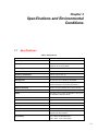
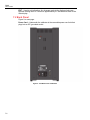
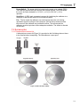
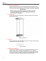
Download User's Guide

Transcript
7102
Micro-Bath
User's Guide
PN 3729328
December 2013
© 2013 Fluke Corporation. All rights reserved. Specifications are subject to change without notice.
All product names are trademarks of their respective companies.
LIMITED WARRANTY AND LIMITATION OF LIABILITY
Each Fluke product is warranted to be free from defects in material and workmanship under normal use and
service. The warranty period is one year and begins on the date of shipment. Parts, product repairs, and
services are warranted for 90 days. This warranty extends only to the original buyer or end-user customer of
a Fluke authorized reseller, and does not apply to fuses, disposable batteries, or to any product which, in
Fluke's opinion, has been misused, altered, neglected, contaminated, or damaged by accident or abnormal
conditions of operation or handling. Fluke warrants that software will operate substantially in accordance
with its functional specifications for 90 days and that it has been properly recorded on non-defective media.
Fluke does not warrant that software will be error free or operate without interruption.
Fluke authorized resellers shall extend this warranty on new and unused products to end-user customers
only but have no authority to extend a greater or different warranty on behalf of Fluke. Warranty support is
available only if product is purchased through a Fluke authorized sales outlet or Buyer has paid the
applicable international price. Fluke reserves the right to invoice Buyer for importation costs of
repair/replacement parts when product purchased in one country is submitted for repair in another country.
Fluke's warranty obligation is limited, at Fluke's option, to refund of the purchase price, free of charge repair,
or replacement of a defective product which is returned to a Fluke authorized service center within the
warranty period.
To obtain warranty service, contact your nearest Fluke authorized service center to obtain return
authorization information, then send the product to that service center, with a description of the difficulty,
postage and insurance prepaid (FOB Destination). Fluke assumes no risk for damage in transit. Following
warranty repair, the product will be returned to Buyer, transportation prepaid (FOB Destination). If Fluke
determines that failure was caused by neglect, misuse, contamination, alteration, accident, or abnormal
condition of operation or handling, including overvoltage failures caused by use outside the product’s
specified rating, or normal wear and tear of mechanical components, Fluke will provide an estimate of repair
costs and obtain authorization before commencing the work. Following repair, the product will be returned to
the Buyer transportation prepaid and the Buyer will be billed for the repair and return transportation charges
(FOB Shipping Point).
THIS WARRANTY IS BUYER'S SOLE AND EXCLUSIVE REMEDY AND IS IN LIEU OF ALL OTHER
WARRANTIES, EXPRESS OR IMPLIED, INCLUDING BUT NOT LIMITED TO ANY IMPLIED WARRANTY
OF MERCHANTABILITY OR FITNESS FOR A PARTICULAR PURPOSE. FLUKE SHALL NOT BE LIABLE
FOR ANY SPECIAL, INDIRECT, INCIDENTAL, OR CONSEQUENTIAL DAMAGES OR LOSSES,
INCLUDING LOSS OF DATA, ARISING FROM ANY CAUSE OR THEORY.
Since some countries or states do not allow limitation of the term of an implied warranty, or exclusion or
limitation of incidental or consequential damages, the limitations and exclusions of this warranty may not
apply to every buyer. If any provision of this Warranty is held invalid or unenforceable by a court or other
decision-maker of competent jurisdiction, such holding will not affect the validity or enforceability of any other
provision.
Fluke Corporation
P.O. Box 9090
Everett, WA 98206-9090
U.S.A.
11/99
To register your product online, visit register.fluke.com
Fluke Europe B.V.
P.O. Box 1186
5602 BD Eindhoven
The Netherlands
Table of Contents
Chapter
1
Title
Page
Before You Start .................................................................................. 1-1
1.1 Symbols Used ................................................................................. 1-1
1.2 Safety Information ........................................................................... 1-2
1.2.1 Warnings ............................................................................... 1-2
1.2.2 Cautions ................................................................................... 1-4
1.3 Authorized Service Centers ............................................................. 1-5
2
Introduction ......................................................................................... 2-1
3
Specifications and Environmental Conditions ................................. 3-1
3.1 Specifications .................................................................................. 3-1
3.2 Environmental Conditions ................................................................ 3-2
4
Quick Start ........................................................................................... 4-1
4.1 Unpacking ........................................................................................ 4-1
4.2 Setup ............................................................................................... 4-2
4.3 Power .............................................................................................. 4-2
4.4 Setting the Temperature .................................................................. 4-2
5
Installation ........................................................................................... 5-1
5.1 Bath Environment ............................................................................ 5-1
5.2 “Dry-out” Period ............................................................................... 5-1
5.3 Bath Preparation and Filling ............................................................ 5-2
5.4 Power .............................................................................................. 5-2
6
Bath Use ............................................................................................... 6-1
6.1 General ............................................................................................ 6-1
6.2 Comparison Calibration ................................................................... 6-2
6.3 Calibration of Multiple Probes.......................................................... 6-2
i
7102
User's Guide
7
Parts and Controls .............................................................................. 7-1
7.1 Front Panel ...................................................................................... 7-1
7.2 Back Panel ...................................................................................... 7-2
7.3 Accessories ..................................................................................... 7-3
7.3.1 Transport/Pour Access Lid ....................................................... 7-3
7.3.2 Access Cover (Optional)........................................................... 7-4
7.3.3 Probe Basket ............................................................................ 7-4
7.3.4 Stir Bar...................................................................................... 7-4
7.3.5 Well Extender (Optional) .......................................................... 7-4
8
General Operation ............................................................................... 8-1
8.1 Changing Display Units ................................................................... 8-1
8.2 Switching to 230V Operation ........................................................... 8-1
8.3 Bath Fluid ........................................................................................ 8-1
8.3.1 Temperature Range ................................................................. 8-2
8.3.2 Viscosity ................................................................................... 8-2
8.3.3 Specific Heat ............................................................................ 8-2
8.3.4 Thermal Conductivity ................................................................ 8-2
8.3.5 Thermal Expansion................................................................... 8-2
8.3.6 Electrical Resistivity .................................................................. 8-3
8.3.7 Fluid Lifetime ........................................................................ 8-3
8.3.8 Safety....................................................................................... 8-3
8.3.9 Cost .......................................................................................... 8-3
8.3.10 Commonly Used Fluids .......................................................... 8-3
8.3.10.1 Water (Distilled) ............................................................... 8-4
8.3.10.2 Mineral Oil ....................................................................... 8-4
8.3.10.3 Silicone Oil (Dow Corning 200.05, 200.10, 200.20) ........ 8-4
8.3.11 Fluid Characteristics Charts ................................................... 8-4
8.3.11.1 Limitations and Disclaimer ............................................... 8-5
8.3.11.2 About the Graph .............................................................. 8-6
8.4 Stirring ............................................................................................. 8-7
8.5 Power .............................................................................................. 8-8
8.6 Thermal Electric Devices (TED) ...................................................... 8-8
8.7 Fluid Drain ....................................................................................... 8-9
8.8 Temperature Controller ................................................................... 8-9
9
Controller Operation ........................................................................... 9-1
9.1 Well Temperature ............................................................................ 9-1
9.2 Temperature Set-point ..................................................................... 9-1
9.2.1 Programmable Set-points ......................................................... 9-1
9.2.2 Set-point Value ......................................................................... 9-3
9.2.3 Temperature Scale Units .......................................................... 9-3
9.3 Scan ................................................................................................ 9-4
9.3.1 Scan Control ............................................................................. 9-4
9.3.2 Scan Rate ................................................................................. 9-4
9.4 Temperature Display Hold ............................................................... 9-4
9.4.1 Hold Temperature Display ........................................................ 9-5
9.4.2 Mode Setting ............................................................................ 9-5
9.4.3 Switch Wiring ............................................................................ 9-5
9.4.4 Switch Test Example ................................................................ 9-6
9.5 Secondary Menu ............................................................................. 9-6
9.6 Thermal Electric Device (TED) ........................................................ 9-6
9.7 Proportional Band ............................................................................ 9-7
9.8 Controller Configuration .................................................................. 9-8
ii
Contents (continued)
9.8.1 Operating Parameters .............................................................. 9-8
9.8.1.1 High Limit ........................................................................... 9-9
9.8.1.2 Stir Speed .......................................................................... 9-9
9.8.2 Serial Interface Parameters ...................................................... 9-9
9.8.2.1 Baud Rate .......................................................................... 9-10
9.8.2.2 Sample Period ................................................................... 9-10
9.8.2.3 Duplex Mode ..................................................................... 9-10
9.8.2.4 Linefeed ............................................................................. 9-11
9.8.3 Calibration Parameters ............................................................. 9-11
9.8.3.1 R0 ...................................................................................... 9-12
9.8.3.2 ALPHA ............................................................................... 9-12
9.8.3.3 DELTA ............................................................................... 9-12
9.8.3.4 C0 and CG ......................................................................... 9-12
9.8.3.5 rCAL .................................................................................. 9-12
10
Digital Communication Interface ....................................................... 10-1
10.1 Serial Communications.................................................................. 10-2
10.1.1 Wiring ..................................................................................... 10-2
10.1.2 Setup ...................................................................................... 10-2
10.1.2.1 Baud Rate ........................................................................ 10-2
10.1.2.2 Sample Period ................................................................. 10-3
10.1.2.3 Duplex Mode ................................................................... 10-3
10.1.2.4 Linefeed ........................................................................... 10-3
10.1.3 Serial Operation...................................................................... 10-3
10.2 Interface Commands ..................................................................... 10-3
11
Test Probe Calibration ........................................................................ 11-1
11.1 Calibrating a Single Probe ............................................................. 11-1
11.2 Stabilization and Accuracy ............................................................ 11-2
12
Calibration Procedure ......................................................................... 12-1
12.1 Calibration Points .......................................................................... 12-1
12.2 Calibration Procedure .................................................................... 12-2
12.2.1 Compute DELTA .................................................................... 12-2
12.2.2 Compute R0 & ALPHA ........................................................... 12-3
12.2.3 Accuracy & Repeatability........................................................ 12-3
13
Maintenance ......................................................................................... 13-1
14
Troubleshooting .................................................................................. 14-1
14.1 Troubleshooting Problems, Possible Causes, and Solutions ........ 14-1
14.2 Comments ..................................................................................... 14-4
14.2.1 EMC Directive......................................................................... 14-4
14.2.2 Low Voltage Directive (Safety) ............................................... 14-4
iii
7102
User's Guide
iv
List of Tables
Table
Title
Page
1.
2.
3.
4.
5.
International Electrical Symbols ................................................................
Specifications ............................................................................................
Table of Various Bath Fluids .....................................................................
Nominal Stirrer Motor SettingsWith Different Liquids ................................
Controller Communications Commands ....................................................
1-1
3-1
8-5
8-8
10-4
v
7102
User's Guide
vi
List of Figures
Figure
Title
Page
1.
2.
3.
4.
5.
6.
7.
8.
7102 Front Panel .......................................................................................
7102 Back Panel and Bottom ....................................................................
Bath Lids and Lid Parts .............................................................................
Probe Basket .............................................................................................
Stir Bar ......................................................................................................
Chart of Various Bath Fluids .....................................................................
Controller Operation Flowchart .................................................................
Serial Cable Wiring....................................................................................
7-1
7-2
7-3
7-4
7-4
8-6
9-2
10-2
vii
7102
User's Guide
viii
Chapter 1
Before You Start
1.1 Symbols Used
Table 1 lists the International Electrical Symbols. Some or all of these symbols
may be used on the instrument or in this manual.
Table 1. International Electrical Symbols
Symbol











O
I

CATII
Description
AC (Alternating Current)
AC-DC
Battery
CE Complies with European Union directives
DC
Double Insulated
Electric Shock
Fuse
PE Ground
Hot Surface (Burn Hazard)
Read the User’s Guide (Important Information)
Off
On
Canadian Standards Association
OVERVOLTAGE (Installation) CATEGORY II, Pollution Degree 2
per IEC1010-1 refers to the level of Impulse Withstand Voltage
protection provided. Equipment of OVERVOLTAGE CATEGORY II
is energy-consuming equipment to be supplied from the fixed
installation. Examples include household, office, and laboratory
appliances.

C-TICK Australian EMC mark

The European Waste Electrical and Electronic Equipment (WEEE)
Directive (2002/96/
EC) mark.
1-1
7102
User's Guide
1.2 Safety Information
Use this instrument only as specified in this manual. Otherwise, the protection
provided by the instrument maybe impaired.
The following definitions apply to the terms “Warning” and “Caution”.
1.2.1
•
“Warning” identifies conditions and actions that may pose hazards to the
user.
•
“Caution” identifies conditions and actions that may damage the instrument
being used.
Warnings
 Warnings
To avoid personal injury, follow these guidelines.
•
Disclaimer: Hart Scientific manufactures instruments for the
purpose of temperature calibration. Instruments used for
applications other than calibration are used at the discretion
and sole responsibility of the customer. Hart Scientific
cannot accept any responsibility for the use of instruments
for any application other than temperature calibration.
GENERAL
1-2
•
DO NOT install an access cover without holes onto a bath
that is energized. Dangerous pressures may result from
fluids vaporizing.
•
DO NOT use the instrument for any application other than
calibration work. The instrument was designed for
temperature calibration. Any other use of the unit may
cause unknown hazards to the user.
•
DO NOT use the unit in environments other than those
listed in the user’s guide. Completely unattended operation
in not recommended.
•
DO NOT install access cover without holes onto a bath that
is energized. Dangerous pressures may result from fluids
vaporizing.
•
Follow all safety guidelines listed in the user’s manual.
•
Calibration Equipment should only be used by Trained
Personnel.
•
If this equipment is used in a manner not specified by the
manufacturer, the protection provided by the equipment
may be impaired or safety hazards may arise.
•
Inspect the instrument for damage before each use. DO NOT
use the instrument if it appears damaged or operates
abnormally.
Before You Start
1
1.2 Safety Information
•
Before initial use, or after transport, or after storage in
humid or semi-humid environments, or anytime the
instrument has not been energized for more than 10 days,
the instrument needs to be energized for a “dry-out” period
of 2 hours before it can be assumed to meet all of the safety
requirements of the IEC 61010-1. If the product is wet or has
been in a wet environment, take necessary measures to
remove moisture prior to applying power such as storage in
a low humidity temperature chamber operating at 50 °C for 4
hours or more.
•
The instrument is intended for indoor use only.
•
Lift the instrument by the handle provided to move the
instrument. DO NOT move the instrument until the display
reads less than 25 °C (77 °F) and the unit has been drained
or the Transport Lid installed.
BURN HAZARD
•
ALWAYS ensure the instrument is COOL before closing the
instrument for storage.
•
DO NOT touch the well access surface of the unit.
•
DO NOT mix water and oil when exceeding temperatures of
90 °C (194 °F).
•
DO NOT mix water and oil when exceeding temperatures of
90 °C (194 °F). The temperature of the well access is the
same as the actual temperature shown on the display, e.g. if
the unit is set at 125 °C and the display reads 125 °C, the
well is at 125 °C.
•
Ensure the power cord is positioned in such a way as it
cannot contact hot surfaces or temperature probes. Always
inspect power cord before use for any damage to the
insulation due to contact with hot surfaces, cuts or
abrasions.
•
The top sheet metal of the instrument may exhibit extreme
temperatures for areas close to the well access.
•
DO NOT turn off the unit at temperatures higher than 100 °C.
This could create a hazardous situation. Select a set-point
less than 100 °C and allow the unit to cool before turning it
off.
•
DO NOT remove the fluid at high temperatures. The fluid will
be the same temperature as the display temperature.
•
DO NOT operate near flammable materials. Extreme
temperatures could ignite the flammable material.
•
Use of this instrument at HIGH TEMPERATURES for
extended periods of time requires caution.
1-3
7102
User's Guide
ELECTRICAL HAZARD
•
These guidelines must be followed to ensure that the safety
mechanisms in this instrument will operate properly. This
instrument must be plugged into an AC only electric outlet
as listed in Section 3.1, Specifications. The power cord of
the instrument is equipped with a three-pronged grounding
plug for your protection against electrical shock hazards. It
must be plugged directly into a properly grounded threeprong receptacle. The receptacle must be installed in
accordance with local codes and ordinances or adapter
plug. DO NOT use an extension cord. Consult a qualified
electrician. Always inspect the power cord before use for
any damage to the insulation due to contact with hot
surfaces, cuts or abrasions.
•
The instrument is equipped with operator accessible fuses.
If a fuse blows, it may be due to a power surge or failure of a
component. Replace the fuse once. If the fuse blows a
second time, it is likely caused by failure of a component
part. If this occurs, contact a Hart Scientific Authorized
Service Center. Always replace the fuse with one of the
same rating, voltage, and type. Never replace the fuse with
one of a higher current rating.
•
Always replace the power cord with an approved cord of the
correct rating and type. If you have questions, contact an
Authorized Service Center (see Section 1.3).
•
High voltage is used in the operation of this equipment.
Severe injury or death may result if personnel fail to
observe the safety precautions.
1.2.2 Cautions
 Cautions
To avoid possible damage to the instrument, follow these
guidelines.
1-4
•
Always operate this instrument at room temperatures listed
in Section 3.2, Environmental Conditions. Allow sufficient
air circulation by leaving at least 6 inches (15 cm) of
clearance around the instrument.
•
Overhead clearance is required. DO NOT place this
instrument under a cabinet or other structure.
•
Never introduce any foreign material into the well.
•
DO NOT change the values of the calibration constants from
the factory set values. The correct setting of these
parameters is important to the safety and proper operation
of the unit.
•
DO NOT slam the probe stems into the well. This type of
action can cause a shock to the sensor and affect the
calibration.
•
DO use a ground fault interrupt device.
Before You Start
1.3 Authorized Service Centers
1.3
•
DO NOT operate this instrument in an excessively wet, oily,
dusty, or dirty environment.
•
The unit is a precision instrument. Although it has been
designed for optimum durability and trouble free operation,
it must be handled with care.
•
Most probes have handle temperature limits. Be sure that
the probe handle temperature limit is not exceeded in the air
above the instrument.
•
The instrument and any thermometer probes used with it
are sensitive instruments that can be easily damaged.
Always handle these devices with care. Do not allow them
to be dropped, struck, stressed, or overheated.
•
When calibrating PRTs always follow correct calibration
procedure and calibrate from high temperatures to low
temperatures with the appropriate triple point of water
checks.
•
Components and heater lifetimes can be shortened by
continuous high temperature operation.
•
If a mains supply power fluctuation occurs, immediately
turn off the bath. Power bumps from brown-outs and blackouts can damage the instrument. Wait until the power has
stabilized before re-energizing the bath.
•
Fluids may expand at different rates. Allow for fluid
expansion inside the well as the instrument heats.
Otherwise, the fluid may overflow the well and leak into the
instrument.
1
Authorized Service Centers
Please contact one of the following authorized Service Centers to coordinate
service on your Hart product:
Fluke Corporation
Hart Scientific Division
799 E. Utah Valley Drive
American Fork, UT 84003-9775
USA
Phone: + 1.801.763.1600
Telefax: +1.801.763.1010
E-mail: [email protected]
1-5
7102
User's Guide
Fluke Nederland B.V.
Customer Support Services
Science Park Eindhoven 5108
5692 EC Son
NETHERLANDS
Phone: +31-402-675300
Telefax: +31-402-675321
E-mail: [email protected]
Fluke Int’l Corporation
Service Center - Instrimpex
Room 2301 Sciteck Tower
22 Jianguomenwai Dajie
Chao Yang District
Beijing 100004, PRC
CHINA
Phone: +86-10-6-512-3436
Telefax: +86-10-6-512-3437
E-mail: [email protected]
Fluke South East Asia Pte Ltd.
Fluke ASEAN Regional Office
Service Center
60 Alexandra Terrace #03-16
The Comtech (Lobby D)
118502
SINGAPORE
Phone: +65-6799-5588
Telefax: +65-6799-5589
E-mail: [email protected]
When contacting these Service Centers for support, please have the following
information available:
1-6
•
Model Number
•
Serial Number
•
Voltage
•
Complete description of the problem
Chapter 2
Introduction
The Hart Scientific 7102 Micro-Bath may be used as a portable instrument or
bench top temperature calibrator for calibrating thermocouple and RTD
temperature probes. The 7102 is small enough to use in the field, and accurate
enough to use in the lab. With an ambient temperature of 23 °C (74 °F),
calibrations may be done over a range of −5 °C to 126 °C (23 °F to 259 °F). The
resolution of the 7102 temperature display is 0.01 degrees.
The Micro-Bath calibrator features:
•
Convenient handle
•
RS-232 interface
•
Switchable AC Input (115 VAC or 230 VAC)
•
Optional well extender to extend well depth
Built in programmable features include:
•
Temperature scan rate control
•
Temperature switch hold
•
Eight Set-point memory
•
Adjustable readout in °C or °F
The temperature is accurately controlled by Hart’s hybrid analog/digital controller.
The controller uses a precision platinum RTD as a sensor and controls the well
temperature with a solid state relay (triac) driven heater.
The LED front panel continuously shows the current well temperature. The
temperature may be easily set with the control buttons to any desired
temperature within the specified range. The calibrator’s multiple fault protection
devices insure user and instrument safety and protection.
The 7102 Micro-Bath was designed for portability, low cost, and ease of
operation. Through proper use, the instrument will continuously provide accurate
calibration of temperature sensors and devices. The user should be familiar with
the safety guidelines and operating procedures of the calibrator as described in
the instruction manual.
2-1
7102
User's Guide
2-2
Chapter 3
Specifications and Environmental
Conditions
3.1
Specifications
Table 2. Specifications
Range
−5 to 125 °C (23 to 257 °F)
Accuracy
±0.25 °C
Stability
±0.015 °C at −5 °C (oil, 5010)
±0.03 °C at 121 °C (oil, 5010)
Uniformity
±0.02 °C
Resolution
0.01 °C/F
Operating Temperature
5 to 45 °C (41 to 113 °F)
Heating Time
25 °C to 100 °C (77 °F to 212 °F): 30 minutes
Cooling Time
25 °C to 0 °C (77 °F to 32 °F): 30 minutes
Well Size
2.5" dia. x 5.5" deep (64 x 139 mm)
(access opening is 1.9" [48 mm] in diameter )
Exterior Dimension
12" H x 7.2" W x 9.5" D (31 cm x 18 cm x 24 cm)
Weight
15 lb. (6.8 kg) with fluid
Power
115 VAC ( ±10 %), 1.8 A, or 230 VAC ( ±10 %), 0.9
A, switchable, 50/60 Hz, 200 W
Readout
Switchable °C or °F
Controller
Digital controller with data retention
Thermal Electric Devices (TED)
150 W
Cooling
Fan and Thermal Electric Devices (TED)
Fault Protection
Sensor burnout and short protection
Safety
Overvoltage (Installation) Category II, Pollution
Degree 2 per IEC 61010-01
Fuse Rating
115 V: 250 V 3A SB (slow blow)
230 V: 250 V 1.6 A T (time delay)
3-1
7102
User's Guide
3.2
Environmental Conditions
Although the instrument has been designed for optimum durability and troublefree operation, it must be handled with care. The instrument should not be
operated in an excessively dusty or dirty environment. Maintenance and cleaning
recommendations can be found in the Maintenance Section of this manual.
3-2
•
The instrument operates safely under the following conditions:
•
ambient temperature range: 5 − 45 °C (41 − 113 °F)
•
ambient relative humidity: maximum 80 % for temperature <31 °C, decreasing
linearly to 50 % at 40 °C
•
mains voltage within ± 10 % of nominal
•
vibrations in the calibration environment should be minimized
•
altitudes less than 2,000 meters
Chapter 4
Quick Start
 Caution:
READ SECTION 6 ENTITLED BATH USE before placing the bath
in service. Incorrect handling can damage the bath and void the
warranty.
4.1
Unpacking
Unpack the Micro-Bath carefully and inspect it for any damage that may have
occurred during shipment. If there is shipping damage, notify the carrier
immediately.
Verify that the following components are present:
•
7102 Micro-Bath
•
Transport/Pour Access Lid
•
Probe Basket
•
Stir Bar
•
Power Cord
•
User’s Guide
•
Report of Calibration
•
Calibration Label
•
Access Cover, optional
•
Well Extender, optional
4-1
7102
User's Guide
4.2 Setup
 Caution:
DO NOT operate this instrument without fluid.
Place the calibrator on a flat surface with at least 6 inches of free space around
the instrument. Plug the power cord into a grounded mains outlet. Observe that
the nominal voltage corresponds to that indicated on the back of the calibrator.
Carefully insert the probe basket into the well. Fill the well with the appropriate
fluid. The set-point temperature and the number of and size of probes determine
the fluid level. Be sure to keep the fluid level an adequate distance below the top
of the well to prevent overflowing the fluid when the probes are inserted. For
example, placing200.05 oil at room temperature (25 °C) into the bath and heating
the unit to 125 °C, causes a 1-inch (2.54 cm) expansion of the fluid inside the
well.
Keep the fluid level at least 1.9 cm (0.75 inches) below the top of the well at
all times. With the probe (probes) in the well fill the tank 3/4 full. Heat to the
maximum temperature of the fluid. Slowly fill the well to 2.54 cm (1 inch) below
the top of the basket at the maximum temperature of the fluid.
Turn on the power to the calibrator by toggling the switch on the power entry
module. The fan should begin blowing air through the instrument and the
controller display should illuminate after 3 seconds. After a brief self test the
controller should begin normal operation. If the unit fails to operate please check
the power connection.
The display shows the well temperature and the well TEDs start operating to
bring the temperature of the well to the set-point temperature. Insure that the fluid
is being stirred.
4.3 Power
Plug the Micro-Bath power cord into a mains outlet of the proper voltage,
frequency, and current capability. Refer to Section 3.1, Specifications, for power
details. Turn the bath on using the rear panel “POWER” switch. The Micro-Bath
will turn on and begin to heat to the previously programmed temperature setpoint. The front panel LED display will indicate the actual bath temperature.
4.4
Setting the Temperature
Section 9.2 explains in detail how to set the temperature set-point on the
calibrator using the front panel keys. The procedure is summarized here.
1. Press “SET” twice to access the set-point value.
2. Press “UP” or “DOWN” to change the set-point value.
3. Press “SET” to store the new set-point.
4. Press “EXIT” to return to the temperature display.
When the set-point temperature is changed the controller switches the heater on
or off to raise or lower the temperature. The displayed well temperature gradually
changes until it reaches the set-point temperature. The well may require 25
minutes to reach the set-point depending on the span. Another 10 to 15 minutes
is required to stabilize within ±0.03 °C of the set-point. Ultimate stability may take
20 to 30 minutes more of stabilization time.
4-2
Chapter 5
Installation
 Caution:
READ SECTION 6 ENTITLED BATH USE before placing the bath
in service. Incorrect handling can damage the bath and void the
warranty.
5.1 Bath Environment
The 7102 Micro Bath is a precision instrument which should be located in an
appropriate environment. The location should be free of drafts, extreme
temperatures and temperature changes, dirt, etc. The surface where the bath is
placed must be level.
Because the bath is designed for operation at high temperatures, keep all
flammable and meltable materials away from the bath. Although the bath is well
insulated, top surfaces do become hot. Beware of the danger of accidental fluid
spills. The bath should be placed on a heat-proof surface such as concrete with
plenty of clear space around the bath.
If the bath is operated at high temperatures, a fume hood should be used to
remove any vapors given off by hot bath fluid.
5.2 “Dry-out” Period
Before initial use, after transport, and any time the instrument has not been
energized for more than 10 days, the bath will need to be energized for a “dryout” period of 1-2 hours before it can be assumed to meet all of the safety
requirements of the IEC 61010-1.
5-1
7102
User's Guide
5.3 Bath Preparation and Filling
The 7102 Micro Bath is not provided with a fluid. Various fluids are available from
Hart Scientific and other sources. Depending on the desired temperature range,
any of the following fluids, as well as others, may be used in the bath:
•
Water (distilled)
•
Ethylene glycol/water
•
Mineral oil
•
Silicone oil
Fluids are discussed in detail in Section 8.3.
Remove the access lid from the bath and check the tank for foreign matter (dirt,
remnant packing material, etc.). Thoroughly dry the inside of the well with paper
towels before filling.
Fill the bath with clean unpolluted fluid. Under-filling may reduce bath
performance. The fluid should never exceed a height of 1.9 cm (0.75 inches)
below the top of the basket. Carefully monitor the bath fluid level as the bath
temperature rises to prevent overflow or splashing. Remove excess hot fluid if
necessary with caution.
Note:
200.05 Silicon Oil expands 2.54 cm (1 inch) for a 100 °C increase in
temperature.
5.4 Power
With the bath power switch off, plug the bath into an AC mains outlet of the
appropriate voltage, frequency, and current capacity. Refer to Section 3.1,
Specifications, for power details.
5-2
Chapter 6
Bath Use
 Caution:
Read before placing the bath in service
The information in this section is for general information only. It
is not designed to be the basis for calibration laboratory
procedures. Each laboratory will need to write their own
specific procedures.
6.1 General
Be sure to select the correct fluid for the temperature range of the calibration.
Bath fluids should be selected to operate safely with adequate thermal properties
to meet the application requirements. Also, be aware that some fluids expand
and could overflow the bath if not watched. Refer to Section 8.3, Bath Fluid, and
subsequent subsections for information specific to fluid selection and to the
MSDS sheet specific to the fluid selected. Generally, baths are set to one
temperature and used to calibrate probes only at that single temperature. This
means that the type of bath fluid does not have to change. Additionally, the bath
can be left energized reducing the stress on the system.
The bath generates extreme temperatures. Precautions must be taken to prevent
personal injury or damage to objects. Probes may be extremely hot or cold when
removed from the bath. Cautiously handle probes to prevent personal injury.
Carefully place probes on a heat/cold resistant surface or rack until they are at
room temperature. It is advisable to wipe the probe with a clean soft cloth or
paper towel before inserting it into another bath. This prevents the mixing of
fluids from one bath to another. If the probe has been calibrated in liquid salt,
carefully wash the probe in warm water and dry completely before transferring it
to another fluid. Always be sure that the probe is completely dry before inserting
it into a hot fluid. Be aware that cleaning the probe can be dangerous if the probe
has not cooled to room temperature. Additionally, high temperature fluids may
ignite the paper towels if the probe has not been cooled.
6-1
7102
User's Guide
 Warning:
Some of the high temperature fluids react violently to water or
other liquid mediums.
For optimum accuracy and stability, allow the bath adequate
stabilization time after reaching the set-point temperature.
6.2 Comparison Calibration
Comparison calibration involves testing a probe (unit under test, UUT) against a
reference probe. After inserting the probes to be calibrated into the bath, allow
sufficient time for the probes to settle and the temperature of the bath to stabilize.
One of the significant dividends of using a bath rather than a dry-well to calibrate
multiple probes is that the probes do not need to be identical in construction. The
fluid in the bath allows different types of probes to be calibrated at the same time.
However, stem effect from different types of probes is not totally eliminated. Even
though all baths have horizontal and vertical gradients, these gradients are
minimized inside the bath work area. Nevertheless, probes should be inserted to
the same depth in the bath liquid. Be sure that all probes are inserted deep
enough to prevent stem effect. From research at Hart Scientific, we suggest a
general rule-of-thumb for immersion depth to reduce the stem effect to a
minimum: 15 x the diameter of the UUT + the sensor length. Do not submerge
the probe handles. If the probe handles get too warm during calibration at high
temperatures, a heat shield could be used just below the probe handle. This heat
shield could be as simple as aluminum foil slid over the probe before inserting it
in the bath or as complicated as a specially designed reflective metal apparatus.
When calibrating over a wide temperature range, better results can generally be
achieved by starting at the highest temperature and progressing down to the
lowest temperature.
Probes can be held in place in the bath by using probe clamps or drilling holes in
the access cover. Other fixtures to hold the probes can be designed. The object
is to keep the reference probe and the probe(s) to be calibrated as closely
grouped as possible in the working area of the bath. Bath stability is maximized
when the bath working area is kept covered.
In preparing to use the bath for calibration start by:
•
Placing the reference probe in the bath working area.
•
Placing the probe to be calibrated, the UUT, in the bath working area as close
as feasibly possible to the reference probe.
6.3 Calibration of Multiple Probes
Fully loading the bath with probes increases the time required for the
temperature to stabilize after inserting the probes. Using the reference probe as
the guide, be sure that the temperature has stabilized before starting the
calibration.
6-2
Chapter 7
Parts and Controls
The user should become familiar with the bath and its parts:
7.1 Front Panel
Figure 1 on this page.
Figure 1. 7102 Front Panel
Controller Display – The digital display is an important part of the temperature
controller because it not only displays set and actual temperatures but also
displays various calibrator functions, settings, and constants. The display shows
temperatures in units according to the selected scale °C or °F.
Controller Keypad – The four button keypad allows easy setting of the set-point
temperature. The control buttons (SET, DOWN, UP, and EXIT) are used to set
the calibrator temperature set-point, access and set other operating parameters,
and access and set calibration parameters.
Setting the control temperature is done directly in degrees of the current scale. It
can be set to one-hundredth of a degree Celsius or Fahrenheit.
The functions of the buttons are as follows:
SET – Used to display the next parameter in the menu and to store parameters
to the displayed value.
DOWN – Used to decrement the displayed value of parameters.
UP – Used to increment the displayed value.
7-1
7102
User's Guide
EXIT – Used to exit a function. Any changes made to the displayed value are
ignored. Holding the EXIT button for approximately 0.5 seconds exits back to the
main display.
7.2 Back Panel
Figure 2 on next page.
Power Cord – Underneath the calibrator is the removable power cord inlet that
plugs into an IEC grounded socket.
Figure 2. 7102 Back Panel and Bottom
7-2
Parts and Controls
7.3 Accessories
7
Power Switch – The power switch is located on the power entry module (PEM).
The PEM also houses the fuses and the dual voltage selector. The PEM allows
the unit to be field switchable for 115 VAC ( ±10 %) or 230 VAC ( ±10 %)
operation.
Serial Port – A DB-9 male connector is present for interfacing the calibrator to a
computer or terminal with serial RS-232 communications.
Fan – The fan inside the calibrator runs continuously when the unit is being
operated to provide cooling for the instrument. Slots at the top and around the
two corners of the calibrator are provided for airflow. The area around the
calibrator must be kept clear to allow adequate ventilation. The airflow is directed
out the back.
7.3 Accessories
7.3.1 Transport/Pour Access Lid
A transport/pour access lid (Figure 3) is provided so the fluid being does not have
to be removed when transporting. The lid doubles as a pour spout.
Figure 3. Bath Lids and Lid Parts
7-3
7102
User's Guide
7.3.2 Access Cover (Optional)
An aluminum access cover (Figure 3) is available for optimum stability. Holes
should be drilled in the access cover to allow insertion of the probes into the well.
The holes must be within the guide ring for the probes to fit into the probe basket.
 Warning:
DO NOT install an access cover without holes (like the optional
cover) onto a bath that is energized. Dangerous pressures may
result from fluids vaporizing.
7.3.3 Probe Basket
A probe basket (Figure 4) is provided as a guide for the probes and to prevent
bumping of the stir bar.
Figure 4. Probe Basket
7.3.4 Stir Bar
The stir bar (Figure 5) sits in the bottom of the well for mixing the fluid providing
better accuracy, uniformity, and stability.
Figure 5. Stir Bar
7.3.5 Well Extender (Optional)
An optional well extender is available for increasing the depth of the well. This
extender screws onto the well and is equipped with an O-ring. Thread the
extender down until the O-ring makes a good seal. Some fluids may expand up
to 6.35 cm (2.5 inches). Therefore, when using the well extender keep in mind
how much the fluid you are using will expand. Do not overfill the well.
7-4
Chapter 8
General Operation
8.1 Changing Display Units
The 7102 can display temperature in Celsius or Fahrenheit.
The temperature units are shipped from the factory set to Celsius.
To change to Fahrenheit or back to Celsius there are two ways:
1. Press “SET” and “UP” simultaneously. This will change the display units.
2. Press the “SET” key three times from the temperature display to show
Un = C
or
•
Press the “UP” or “DOWN” key to change units.
•
Press “SET” to store changes.
8.2 Switching to 230V Operation
The 7102 is switchable from 115 VAC to 230 VAC 50/60 Hz. Switching the
voltage can change the calibration, so the unit should be calibrated after
changing the input voltage.
To change from 115 VAC to 230 VAC:
•
Unplug the unit.
•
With a small straight slot screwdriver remove the fuse holder located on the
back of the bath. Replace the two fuses (3 amp 250 V) with 1.6 amp 250 V
fuses.
•
Replace the fuse holder with the “230V” in the display window.
Note:
Use 3 amp fuses for 115 V and 1.6 amp for 230V only. DO NOT
PLUG THE UNIT INTO 230 V IF THE FUSE HOLDER READS 115 V.
8-1
7102
User's Guide
8.3
Bath Fluid
Many fluids work with the 7102 bath. Choosing a fluid requires consideration of
many important characteristics of the fluid. Among these are temperature range,
viscosity, specific heat, thermal conductivity, thermal expansion, electrical
resistivity, fluid lifetime, safety, and cost.
8.3.1 Temperature Range
One of the most important characteristics to consider is the temperature range of
the fluid. Few fluids work well throughout the complete temperature range of the
bath. The temperature at which the bath is operated must always be within the
safe and useful temperature range of the fluid. The lower temperature range of
the fluid is determined by the freeze point of the fluid or the temperature at which
the viscosity becomes too great. The upper temperature is usually limited by
vaporization, flammability, or chemical breakdown of the fluid. Vaporization of the
fluid at higher temperatures may affect temperature stability because of cool
condensed fluid dripping into the bath from the lid.
8.3.2 Viscosity
Viscosity is a measure of the thickness of a fluid, how easily it can be poured and
mixed. Viscosity affects the temperature stability of the bath. With low viscosity,
fluid mixing is better which creates a more uniform temperature throughout the
bath. This improves the bath response time which allows it to maintain a more
constant temperature. For good control the viscosity should be less than ten
centistokes. Twenty centistokes is about the upper limit of allowable viscosity.
Viscosities greater than this cause very poor control stability and may also
overheat or damage the stirring motor. With oils viscosity may vary greatly with
temperature.
When using fluids with higher viscosities the controller proportional band may
need to be increased to compensate for the reduced response time. Otherwise
the temperature may begin to oscillate.
8.3.3 Specific Heat
Specific heat is the measure of the heat storage ability of the fluid. Specific heat,
to a small degree, affects the control stability. It also affects the heating and
cooling rates. Generally, a lower specific heat means quicker heating and
cooling. The proportional band may require some adjustment depending on the
specific heat of the fluid.
8.3.4 Thermal Conductivity
Thermal conductivity measures how easily heat flows through the fluid. Thermal
conductivity of the fluid affects the control stability, temperature uniformity, and
probe temperature settling time. Fluids with higher conductivity distribute heat
more quickly and evenly improving bath performance.
8-2
General Operation
8.3
Bath Fluid
8
8.3.5 Thermal Expansion
Thermal expansion describes how the volume of the fluid changes with
temperature. Thermal expansion of the fluid used must be considered since the
increase in fluid volume as the bath temperature changes may cause overflow.
Excessive thermal expansion may also be undesirable in applications where
constant liquid level is important. Many fluids including oils have significant
thermal expansion.
8.3.6 Electrical Resistivity
Electrical resistivity describes how well the fluid insulates against the flow of
electric current. In some applications, such as measuring the resistance of bare
temperature sensors, it may be important that little or no electrical leakage occur
through the fluid. In such conditions choose a fluid with very high resistivity.
8.3.7 Fluid Lifetime
Many fluids degrade over time because of evaporation, water absorption, gelling,
or chemical breakdown. Often the degradation becomes significant near the
upper temperature limit of the fluid, substantially reducing the fluid’s lifetime.
8.3.8
Safety
When choosing a fluid always consider the safety issues associated. Obviously
where there are conditions of extreme hot or cold there can be danger to people
and equipment. Fluids may also be hazardous for other reasons. Some fluids
may be considered toxic. Contact with eyes, skin, or inhalation of vapors may
cause injury. A proper fume hood must be used if hazardous or bothersome
vapors are produced.
 Warning:
Fluids at high temperatures may pose danger from BURNS,
FIRE, and TOXIC FUMES. Use appropriate caution and safety
equipment.
Fluids may be flammable and require special fire safety equipment and
procedures. An important characteristic of the fluid to consider is the flash point.
The flash point is the temperature at which there is sufficient vapor given off so
that when there is sufficient oxygen present and an ignition source is applied the
vapor will ignite. This does not necessarily mean that fire will be sustained at the
flash point. The flash point may be either of the open cup or closed cup type.
Either condition may occur in a bath situation. The closed cup temperature is
always the lower of the two. The closed cup represents the contained vapors
inside the tank and the open cup represents the vapors escaping the tank.
Oxygen and an ignition source will be less available inside the tank.
Environmentally hazardous fluids require special disposal according to applicable
federal or local laws after use.
8.3.9 Cost
Cost of bath fluids may vary greatly, from cents per gallon for water to hundreds
of dollars per gallon for synthetic oils. Cost may be an important consideration
when choosing a fluid.
8-3
7102
User's Guide
8.3.10 Commonly Used Fluids
Below is a description of some of the more commonly used fluids and their
characteristics.
8.3.10.1 Water (Distilled)
Water is often used because of its very low cost, availability, and excellent
temperature control characteristics. Water has very low viscosity and good
thermal conductivity and heat capacity which makes it among the best fluids for
control stability at low temperatures. Temperature stability is much poorer at
higher temperatures because water condenses on the lid, cools and drips into
the bath. Water is safe and relatively inert. The electrical conductivity of water
may prevent its use in some applications. Water has a limited temperature range,
from a few degrees above 0 °C to a few degrees below 100 °C. At higher
temperatures evaporation becomes significant. Water used in the bath should be
distilled or softened to prevent mineral deposits. Consider using an algaecide
chemical in the water to prevent contamination.
8.3.10.2 Mineral Oil
Mineral oil or paraffin oil is often used at moderate temperatures above the range
of water. Mineral oil is relatively inexpensive. At lower temperatures mineral oil is
quite viscous and control may be poor. At higher temperatures vapor emission
becomes significant. The vapors may be dangerous and use of a fume hood is
highly recommended. As with most oils mineral oil will expand as temperature
increases so be careful not to fill the bath too full that it overflows when heated.
The viscosity and thermal characteristics of mineral oil is poorer than water so
temperature stability will not be as good. Mineral oil has very low electrical
conductivity. Use caution with mineral oil since it is flammable and may also
cause serious injury if inhaled or ingested.
8.3.10.3 Silicone Oil (Dow Corning 200.05, 200.10, 200.20)
Silicone oils are available which offer a much wider operating temperature range
than mineral oil. Like most oils, silicone oils have temperature control
characteristics which are somewhat poorer than water. The viscosity changes
significantly with temperature and thermal expansion also occurs. These oils
have very high electrical resistivity. Silicone oils are fairly safe and non-toxic.
Silicone oils are fairly expensive.
8.3.11 Fluid Characteristics Charts
Table 3 on page 25 and Figure 6 on page 26 have been created to provide help
in selecting a heat exchange fluid media for your constant temperature bath.
These charts provide both a visual and numerical representation of most of the
physical qualities important in making a selection. The list is not all inclusive.
There may be other useful fluids not shown in this listing.
The charts include information on a variety of fluids which often used as heat
transfer fluid in baths. Because of the temperature range some fluids may not be
useful with your bath.
8-4
General Operation
8.3
Bath Fluid
8
8.3.11.1 Limitations and Disclaimer
The information given in this manual regarding fluids is intended only to be used
as a general guide in choosing a fluid. Though every effort has been made to
provide correct information we cannot guarantee accuracy of data or assure
suitability of a fluid for a particular application. Specifications may change and
sources sometimes offer differing information. Hart Scientific cannot be liable for
any personal injury or damage to equipment, product or facilities resulting from
the use of these fluids. The user of the bath is responsible for collecting correct
information, exercising proper judgment, and insuring safe operation. Operating
near the limits of certain properties such as the flash point or viscosity can
compromise safety or performance. Your company’s safety policies regarding
flash points, toxicity, and such issues must be considered. You are responsible
for reading the MSDS (material safety data sheets) and acting accordingly.
Table 3. Table of Various Bath Fluids
8-5
7102
User's Guide
Figure 6. Chart of Various Bath Fluids
8.3.11.2 About the Graph
The fluid graph visually illustrates some of the important qualities of the fluids
shown.
Temperature Range: The temperature scale is shown in degrees Celsius. The
fluids’ general range of application is indicated by the shaded bands. Qualities
including pour point, freeze point, important viscosity points, flash point, boiling
point and others may be shown.
Freezing Point: The freezing point of a fluid is an obvious limitation to stirring.
As the freezing point is approached high viscosity may also limit performance.
8-6
8
General Operation
8.4 Stirring
Pour Point: This represents a handling limit for the fluid.
Viscosity: Points shown are at 50 and 10 centistokes viscosity. When viscosity
is greater than 50 centistokes stirring is very poor and the fluid is unsatisfactory
for bath applications. Optimum stirring generally occurs at 10 centistokes and
below.
Fume Point: A fume hood should be used. This point is very subjective in nature
and is impacted by individual tolerance to different fumes and smells, how well
the bath is covered, the surface area of the fluid in the bath, the size and
ventilation of the facility where the bath is located and other conditions. We
assume the bath is well covered at this point. This is also subject to company
policy.
Flash Point: The point at which ignition may occur. The point shown may be
either the open or closed cup flash point. Refer to the flash point discussion in
Section 8.3.8.
Boiling Point: At or near the boiling point of the fluid, the temperature stability is
difficult to maintain. Fuming or evaporation is excessive. Large amounts of heater
power may be required because of the heat of vaporization.
Decomposition: The temperature may reach a point at which decomposition of
the fluid begins. Further increasing the temperature may accelerate
decomposition to the point of danger or impracticality.
8.4 Stirring
Stirring of the bath fluid is very important for stable temperature control. The fluid
must be mixed well for good temperature uniformity and fast controller response.
The stirrer is adjusted for optimum performance. Table 4 on page 27 shows
nominal stirrer motor settings for several fluids.
If the stirrer does not function properly, the instrument will oscillate and not meet
published specifications.
Note:
If the bath is used with the probe basket removed, stir motor settings
need to be changed so that a small vortex can be seen in the liquid.
8-7
7102
User's Guide
 Warning:
Do not mix water and oil when exceeding temperatures of 90 °C
Table 4. Nominal Stirrer Motor Settings with Different Liquids
Liquid
Distilled Water
Stir Motor Setting
15
Temperature
5 °C to 90 °C
(41 °F to 194 °F)
Ethylene Glycol
15
−5 °C to 90 °C
(25 °F to 194 °F)
200.05 Oil
15
−5 °C to 125 °C
( −23 °F to 258 °F)
200.10 Oil
15
25 °C to 125 °C
(77 °F to 258 °F)
8.5 Power
Power to the bath is provided by an AC mains supply and passes through a filter
to prevent switching spikes from being transmitted to other equipment. Refer to
Section 3.1, Specifications, for power details.
To turn on the bath, switch the control panel power switch to the ON position.
The stir motor will turn on, the LED display will begin to show the bath
temperature, and the heater will turn on or off until the bath temperature reaches
the programmed set-point.
When powered on the control panel display will briefly show a four digit number.
This number indicates the number of times power has been applied to the bath.
Also briefly displayed is data which indicates the controller hardware
configuration. This data is used in some circumstances for diagnostic purposes.
8.6 Thermal Electric Devices (TED)
The power to the bath is precisely controlled by the temperature controller to
maintain a constant bath temperature. Power is controlled by periodically
switching the TEDs on for a certain amount of time using power transistors.
8-8
8
General Operation
8.7 Fluid Drain
8.7 Fluid Drain
The fluid may be drained from the 7102 by tightly screwing the transport/pour
access lid onto the top of the bath and pouring the liquid into an appropriate
container.
8.8 Temperature Controller
The bath temperature is controlled by Hart Scientific’s unique hybrid
digital/analog temperature controller. The controller offers the tight control
stability of an analog temperature controller as well as the flexibility and
programmability of a digital controller.
The bath temperature is monitored with a platinum resistance sensor in the
control probe. The signal is electronically compared with the programmable
reference signal, amplified, and then fed to a pulse-width modulator circuit which
controls the amount of power applied to the bath heater.
The bath is operable within the temperature range given in the specifications. For
protection against solid-state relay failure or other circuit failure, a bi-metallic cutout automatically turns off the heater anytime the bath temperature exceeds the
maximum temperature.
The controller allows the operator to set the bath temperature with high
resolution, adjust the proportional band, monitor the heater output power, and
program the controller configuration and calibration parameters. The controller
may be operated in temperature units of degrees Celsius or Fahrenheit. The
controller is operated and programmed from the front control panel using the four
key switches and digital LED display. The controller is equipped with a serial RS232 digital interface for remote operation. Operation using the digital interfaces is
discussed in Section 10.
When the controller is set to a new set-point the bath heats or cools to the new
temperature. Once the new temperature is reached the bath usually takes 15 –
20 minutes for the temperature to settle and stabilize. There may be a small
overshoot or undershoot.
8-9
7102
User's Guide
8-10
Chapter 9
Controller Operation
This chapter discusses in detail how to operate the bath temperature controller
using the front control panel. Using the front panel key-switches and LED display
the user may monitor the well temperature, set the temperature set-point in
degrees C or F, monitor the heater output power, adjust the controller
proportional band, and program the calibration parameters, operating
parameters, and serial interface configuration. Operation of the functions and
parameters are shown in the flowchart in Figure 7 on page 32. This chart may be
copied for reference.
In the following discussion a button with the word SET, UP, EXIT or DOWN
inside indicates the panel button while the dotted box indicates the display
reading. Explanation of the button or display reading are to the right of each
button or display value.
9.1 Well Temperature
The digital LED display on the front panel allows direct viewing of the actual well
temperature. This temperature value is what is normally shown on the display.
The units, C or F, of the temperature value are displayed at the right. For
example,
100.00C
Well temperature in degrees Celsius
The temperature display function may be accessed from any other function by
pressing the “EXIT” button.
9.2
Temperature Set-point
The temperature set-point can be set to any value within the range and resolution
as given in the specifications. Be careful not to exceed the safe upper
temperature limit of any device inserted into the well.
Setting the temperature involves selecting the set-point memory and adjusting
the set- point value.
9.2.1 Programmable Set-points
The controller stores 8 set-point temperatures in memory. The set-points can be
quickly recalled to conveniently set the calibrator to a previously programmed
temperature set-point.
To set the temperature one must first select the set-point memory. This function
is accessed from the temperature display function by pressing “SET”. The
number of the set-point memory currently being used is shown at the left on the
display followed by the current set-point value.
9-1
7102
User's Guide
Figure 7. Controller Operation Flowchart
9-2
Controller Operation
9.2
100.00C
Temperature Set-point
9
Well temperature in degrees Celsius
Access set-point memory
1. 25
Set-point memory 1, 25 °C currently used
To change the set-point memory press “UP” or “DOWN”.
4. 125.
New set-point memory 4, 125 °C
Press “SET” to accept the new selection and access the set-point value.
Accept selected set-point memory
9.2.2 Set-point Value
The set-point value may be adjusted after selecting the set-point memory and
pressing “SET”.
4 125.
Set-point 4 value in °C
If the set-point value is correct, hold “EXIT” to resume displaying the well
temperature. Press “UP” or “DOWN” to adjust the set-point value.
125.00
New set-point value
When the desired set-point value is reached press “SET” to accept the new value
and access the temperature scale units selection. If “EXIT” is pressed instead of
“SET”, any changes made to the set-point are ignored.
Accept new set-point value
9.2.3 Temperature Scale Units
The temperature scale units of the controller can be set by the user to degrees
Celsius ( °C) or Fahrenheit ( °F). The selected units are used in displaying the
well temperature, set-point, and proportional band.
Press “SET” after adjusting the set-point value to change display units.
Un= C
Scale units currently selected
Press “UP” or “DOWN” to change the units.
Un= F
New units selected
9-3
7102
User's Guide
9.3 Scan
The scan rate can be set and enabled so that when the set-point is changed the
bath heats or cools at a specified rate (degrees per minute) until it reaches the
new set-point. With the scan disabled the bath heats or cools at the maximum
possible rate.
9.3.1
Scan Control
The scan is controlled with the scan on/off function that appears in the main
menu after the set-point function.
Sc=OFF
Scan function off
Press “UP” or “DOWN” to toggle the scan on or off.
Sc=On
Scan function on
Press “SET” to accept the present setting and continue.
Accept scan setting
9.3.2
Scan Rate
The next function in the main menu is the scan rate. The scan rate can be set
from .1 to 99.9 °C/min. The maximum scan rate however is actually limited by the
natural heating or cooling rate of the instrument. This is often less than
100 °C/min, especially when cooling.
The scan rate function appears in the main menu after the scan control function.
The scan rate units are in degrees C per minute.
Sr= 10.0
Scan rate in °C/min
Press “UP” or “DOWN” to change the scan rate.
Sr= 2.0
New scan rate
Press “SET” to accept the new scan rate and continue.
Accept scan rate
9.4 Temperature Display Hold
The 7102 has a display hold function which allows action of an external switch to
freeze the displayed temperature and stop the set-point from scanning. This is
useful for testing thermal switches and cut-outs. The instrument must be
powered off before attaching thermal switches or cut-outs. This section explains
the functions available for operating the temperature hold feature. An example
follows showing how to set up and use the hold feature to test a switch.
9-4
Controller Operation
9.4 Temperature Display Hold
9
9.4.1 Hold Temperature Display
The hold feature is enabled by simply pressing the “UP” button when the
temperature is displayed. The hold temperature display shows the hold
temperature on the right and the switch status on the left. For the status “c”
means the switch is closed and “o” means the switch is open. The status flashes
when the switch is in its active position (opposite the normal position). The hold
temperature shows what the temperature of the well was when the switch
changed from its normal position to its active position. While the switch is in the
normal position the hold temperature will follow the well temperature.
If the Scan Control is “OFF” and the Hold Temperature Display is being used, the
temperature at which the switch is activated does not affect the set-point
temperature. However, if the Scan Control is “ON” and the Hold Temperature
Display is being used, the temperature at which the switch is activated is stored
as the new set-point temperature.
Operation of the hold temperature display is outlined below.
143.50C
Well temperature display
Access hold display
c 144.8
Switch status and hold temperature
To return to the normal well temperature display press “DOWN”.
9.4.2 Mode Setting
The Hold Function is always in the automatic mode. In this mode the normal
position is set to whatever the switch position is when the set-point is changed.
For example, if the switch is currently open when the set-point is changed, the
closed position then becomes the new active position. The normal position will be
set automatically under any of the following conditions, (1) a new set-point
number is selected, (2)the set-point value is changed, (3) a new set-point is set
through the communications channels.
9.4.3 Switch Wiring
The thermal switch or cut-out is wired to the calibrator at the two terminals on the
back of the Micro-Bath labeled “DISPLAY HOLD”. The switch wires may be
connected to the terminals either way. Internally the black terminal connects to
ground. The red terminal connects to +5V through a 100 kW resistor. The
calibrator measures the voltage at the red terminal and interprets +5V as open
and 0V as closed.
9-5
7102
User's Guide
9.4.4 Switch Test Example
This section describes a possible application for the temperature hold feature
and how the instrument is set up and operated.
Suppose you have a thermal switch which is supposed to open at about 75 °C
and close at about 50 °C and you want to test the switch to see how accurate
and repeatable it is. You can use the temperature hold feature and the scan
function to test the switch. Measurements can be made by observing the display
or, preferably, by collecting data using a computer connected to the RS-232 port.
To set up the test do the following steps.
1. Connect the switch wires to the terminals on the back of the Micro-Bath and
place the switch in the well.
2. Enable set-point scanning by setting the scan to “ON” in the primary menu
(see Section 9.3.1).
3. Set the scan rate to a low value, say 1.0 °C/min. (see Section 9.3.2). If the
scan rate is too high you may lose accuracy because of transient temperature
gradients. If the scan rate is too low the duration of the test may be longer
than is necessary. You may need to experiment to find the best scan rate.
4. Set the first program set-point to a value above the expected upper switch
temperature, say 90 °C.
5. Set the second program set-point to a value below the expected lower switch
temperature, say 40 °C, in the program menu.
6. Collect data on a computer connected to the RS-232 port. Refer to Section
9.8.2, Serial Interface Parameters, for instructions on configuring the RS-232
communications interface.
9.5 Secondary Menu
Functions which are used less often are accessed within the secondary menu.
The secondary menu is accessed by pressing “SET” and “EXIT” simultaneously
and then releasing. The first function in the secondary menu is the heater power
display. (See Figure 7 on page 32.)
9.6 Thermal Electric Device (TED)
The temperature controller controls the temperature of the well by pulsing the
TED on and off. The total power being applied to the TED is determined by the
duty cycle or the ratio of TED on time to the pulse cycle time. By knowing the
amount of heating the user can tell if the calibrator is heating up to the set-point,
cooling down, or controlling at a constant temperature. Monitoring the percent
heater power will let the user know how stable the well temperature is. With good
control stability the percent heating power should not fluctuate more than ±5 %
within one minute.
9-6
Controller Operation
9.7 Proportional Band
9
The heater power display is accessed in the secondary menu. Press “SET” and
“EXIT” simultaneously and release. The heater power will be displayed as a
percentage of full power.
100.00C
Well temperature
+
Access heater power in secondary menu
SEC
Flashes
12.0 P
Heater power in percent
To exit out of the secondary menu hold “EXIT”. To continue on to the proportional
band setting function press “EXIT” momentarily or “SET”.
9.7 Proportional Band
In a proportional controller such as this the heater output power is proportional to
the well temperature over a limited range of temperatures around the set-point.
This range of temperature is called the proportional band. At the bottom of the
proportional band the heater output is 100 %. At the top of the proportional band
the heater output is 0. Thus as the temperature rises the heater power is
reduced, which consequently tends to lower the temperature back down. In this
way the temperature is maintained at a fairly constant temperature.
The temperature stability of the well and response time depend on the width of
the proportional band. If the band is too wide the well temperature will deviate
excessively from the set-point due to varying external conditions. This is because
the power output changes very little with temperature and the controller cannot
respond very well to changing conditions or noise in the system. If the
proportional band is too narrow the temperature may swing back and forth
because the controller overreacts to temperature variations. For best control
stability the proportional band must be set for the optimum width.
The proportional band width is set at the factory to about 5.0 °C. The proportional
band width may be altered by the user if he desires to optimize the control
characteristics for a particular application.
9-7
7102
User's Guide
The proportional band width is easily adjusted from the front panel. The width
may be set to discrete values in degrees C or F depending on the selected units.
The proportional band adjustment is be accessed within the secondary menu.
Press “SET” and “EXIT” to enter the secondary menu and show the heater
power. Then press “SET” to access the proportional band.
+
12.0 P
Access heater power in secondary menu
Heater power in percent
Access proportional band
ProP
Flashes “ProP” and the setting
5.0
Proportional band setting
To change the proportional band press “UP” or “DOWN”.
4.0
New proportional band setting
To store the new setting press “SET”. Press “EXIT” to continue without storing
the new value.
Accept the new proportional band setting
9.8 Controller Configuration
The controller has a number of configuration and operating options and
calibration parameters which are programmable via the front panel. These are
accessed from the secondary menu after the proportional band function by
pressing “SET”. Pressing “SET” again enters the first of three sets of
configuration parameters: operating parameters, serial interface parameters, and
calibration parameters. The menus are selected using the “UP” and “DOWN”
keys and then pressing “SET”. (See Figure 7 on page 32.)
9.8.1 Operating Parameters
The operating parameters menu is indicated by,
PAr
Operating parameters menu
The operating parameters menu contains the High Limit and Stir Speed
parameters.
9-8
Controller Operation
9.8 Controller Configuration
9
9.8.1.1 High Limit
The High Limit Parameter adjusts the upper set-point temperature. The factory
default and maximum temperature are set to 126 °C. For safety, a user can
adjust the HL down so the maximum temperature set-point is restricted.
HL
High Limit parameter
Press “SET” to enable adjustment of HL
HL
Flashes “HL” and then displays the setting
H=126
Current HL setting
Adjust the HL parameter using “UP” or “DOWN”
H=90
New HL setting
Press “SET “to accept the new temperature limit.
9.8.1.2 Stir Speed
The Stir Speed parameter adjusts stirrer motor speed. The factory default is 20.
Str SP
Flashes “Str Sp” and then displays the setting
0
Current Stir Speed setting
To change the stir speed press “UP” or “DOWN”.
16
New Stir Speed setting
Press “SET” to accept the new Stir Speed.
The stir motor speed needs to be varied for best stability. Table 3 on page 25
shows nominal settings for several fluids.
9.8.2
Serial Interface Parameters
The serial RS-232 interface parameters menu is indicated by,
SErIAL
Serial RS-232 interface parameters menu
The serial interface parameters menu contains parameters which determine the
operation of the serial interface. These controls only apply to instruments fitted
with the serial interface. The parameters in the menu are — baud rate, sample
period, duplex mode, and linefeed. Press “UP” to enter the menu.
9-9
7102
User's Guide
9.8.2.1 Baud Rate
The baud rate is the first parameter in the menu. The baud rate setting
determines the serial communications transmission rate.
The baud rate parameter is indicated by,
bAUd
Flashes “bAUd” and then displays the setting
2400 b
Current baud rate
The baud rate of the serial communications may be programmed to 300, 600,
1200,2400, 4800, or 9600 baud. Use “UP” or “DOWN” to change the baud rate
value.
4800 b
New baud rate
Press “SET” to set the baud rate to the new value or “EXIT” to abort the
operation and skip to the next parameter in the menu.
9.8.2.2 Sample Period
The sample period is the next parameter in the serial interface parameter menu.
The sample period is the time period in seconds between temperature
measurements transmitted from the serial interface. If the sample rate is set to 5,
the instrument transmits the current measurement over the serial interface
approximately every five seconds. The automatic sampling is disabled with a
sample period of 0. The sample period is indicated by,
SPer
Flashes “SPEr” and then displays the setting
SP= 1
Current sample period (seconds)
Adjust the value with “UP” or “DOWN” and then use “SET” to store the sample
rate to the displayed value. “EXIT” does not store the new value.
SP= 60
New sample period
9.8.2.3 Duplex Mode
The next parameter is the duplex mode. The duplex mode may be set to full
duplex or half duplex. With full duplex any commands received by the calibrator
via the serial interface will be immediately echoed or transmitted back to the
device of origin. With half duplex the commands will be executed but not echoed.
The duplex mode parameter is indicated by,
dUPL
9-10
Flashes “dUPL” and then displays the setting
Controller Operation
9.8 Controller Configuration
d=FULL
9
Current duplex mode setting
The mode may be changed using “UP” or “DOWN” and pressing “SET”.
d=HALF
New duplex mode setting
9.8.2.4 Linefeed
The final parameter in the serial interface menu is the linefeed mode. This
parameter enables (on) or disables (off) transmission of a linefeed character (LF,
ASCII 10) after transmission of any carriage-return. The linefeed parameter is
indicated by,
LF
Flashes “LF” and then displays the setting
LF= On
Current linefeed setting
The mode may be changed using “UP” or “DOWN” and pressing “SET”.
LF= OFF
9.8.3
New linefeed setting
Calibration Parameters
The operator of the Micro-Bath controller has access to a number of the bath
calibration constants namely R0, ALPHA, DELTA, C0, CG, and rCAL. These
values are set at the factory and should not be altered. The correct values are
important to the accuracy and proper and safe operation of the bath. Access to
these parameters is available to the user only so that in the event that the
controller memory fails the user may restore these values to the factory settings.
The user should have a list of these constants and their settings with manual.
 Caution:
DO NOT change the values of the bath calibration constants
from the factory set values. The correct setting of these
parameters is important to the safety and proper operation of
the bath.
The calibration parameters menu is indicated by:
CAL
Calibration parameters menu
Press “SET” five times to enter the menu.
The calibration parameters R0, ALPHA, DELTA, C0, CG, and rCAL characterize
the resistance-temperature relationship of the platinum control sensor. These
parameters may be adjusted by an experienced user to improve the accuracy of
the calibrator.
9-11
7102
User's Guide
9.8.3.1 R0
This probe parameter refers to the resistance of the control probe at 0 °C. The
value of this parameter is set at the factory for best instrument accuracy.
9.8.3.2 ALPHA
This probe parameter refers to the average sensitivity of the probe between 0
and 100 °C. The value of this parameter is set at the factory for best instrument
accuracy.
9.8.3.3 DELTA
This probe parameter characterizes the curvature of the resistance-temperature
relationship of the sensor. The value of this parameter is set at the factory for
best instrument accuracy.
9.8.3.4 C0 and CG
These parameters calibrate the accuracy of the bath set-point. These are
programmed at the factory when the bath is calibrated. DO NOT alter the value
of these parameters. If the user desires to calibrate the bath for improved
accuracy then calibrate R0 and ALPHA according to the procedure in Section 12.
9.8.3.5 rCAL
DO NOT adjust this parameter. It is for factory use only.
9-12
Chapter 10
Digital Communication Interface
The Micro-Bath calibrator is capable of communicating with and being controlled
by other equipment through the digital serial interface.
With a digital interface the instrument may be connected to a computer or other
equipment. This allows the user to set the set-point temperature, monitor the
temperature, and access any of the other controller functions, all using remote
communications equipment. Communications commands are summarized in
Table 5.
10-1
7102
User's Guide
10.1 Serial Communications
The calibrator is installed with an RS-232 serial interface that allows serial digital
communications over fairly long distances. With the serial interface the user may
access any of the functions, parameters and settings discussed in Section 9 with
the exception of the baud rate setting.
10.1.1 Wiring
The serial communications cable attaches
to the calibrator through the DB-9 connector
at the back of the instrument. Figure 8
shows the pin-out of this connector and
suggested cable wiring. To eliminate noise
the serial cable should be shielded with low
resistance between the connector (DB-9)
and the shield. If the unit is used in a heavy
industrial setting, the serial cable must be
limited to ONE METER in length.
10.1.2 Setup
Before operation the serial interface must
first be set up by programming the baud
rate and other configuration parameters.
These parameters are programmed within
the serial interface menu. The serial
interface parameters menu is outlined in
Figure 7 on page 32.
F
Figure 8. Serial Cable Wiring
To enter the serial parameter programming mode first press “EXIT” while
pressing “SET” and release to enter the secondary menu. Press “SET”
repeatedly until the display reads “PAr”. Press “UP” until the serial interface
menu is indicated with “Serial”. Finally press “SET” to enter the serial parameter
menu. In the serial interface parameters menu are the baud rate, the sample
rate, the duplex mode, and the linefeed parameter.
10-2
10
Digital Communication Interface
10.1 Serial Communications
10.1.2.1 Baud Rate
The baud rate is the first parameter in the menu. The display will prompt with the
baud rate parameter by showing “bAUd”. Press “SET” to choose to set the baud
rate. The current baud rate value will then be displayed. The baud rate of the
7102 serial communications may be programmed to 300, 600, 1200, 2400, 4800,
or 9600 baud. The baud rate is pre-programmed to 2400 baud. Use “UP” or
“DOWN” to change the baud rate value. Press “SET” to set the baud rate to the
new value or “EXIT” to abort the operation and skip to the next parameter in the
menu.
10.1.2.2 Sample Period
The sample period is the next parameter in the menu and prompted with “SPEr”.
The sample period is the time period in seconds between temperature
measurements transmitted from the serial interface. If the sample rate is set to 5,
the instrument transmits the current measurement over the serial interface
approximately every five seconds. The automatic sampling is disabled with a
sample period of 0. Press “SET” to choose to set the sample period. Adjust the
period with “UP” or “DOWN” and then use “SET” to set the sample rate to the
displayed value.
10.1.2.3 Duplex Mode
The next parameter is the duplex mode indicated with “dUPL”. The duplex mode
may be set to half duplex (“HALF”) or full duplex (“FULL”). With full duplex any
commands received by the thermometer via the serial interface will be
immediately echoed or transmitted back to the device of origin. With half duplex
the commands will be executed but not echoed. The default setting is full duplex.
The mode may be changed using “UP” or “DOWN” and pressing “SET”.
10.1.2.4 Linefeed
The final parameter in the serial interface menu is the linefeed mode. This
parameter enables (“On”) or disables (“OFF”) transmission of a linefeed
character (LF, ASCII10) after transmission of any carriage-return. The default
setting is with linefeed on. The mode may be changed using “UP” or “DOWN”
and pressing “SET”.
10.1.3 Serial Operation
Once the cable has been attached and the interface set up properly the controller
will immediately begin transmitting temperature readings at the programmed rate.
The serial communications uses 8 data bits, one stop bit, and no parity. The setpoint and other commands may be sent via the serial interface to set the
temperature set-point and view or program the various parameters. The interface
commands are discussed in Section 10.2. All commands are ASCII character
strings terminated with a carriage- return character (CR, ASCII 13).
10-3
7102
User's Guide
10.2 Interface Commands
The various commands for accessing the calibrator functions via the digital
interfaces are listed in this section (see Table 5). These commands are used with
the RS-232 serial interface. The commands are terminated with a carriage-return
character. The interface makes no distinction between upper and lower case
letters, hence either may be used. Commands may be abbreviated to the
minimum number of letters which determines a unique command. A command
may be used to either set a parameter or display a parameter depending on
whether or not a value is sent with the command following a “ =” character. For
example “s” <CR > will return the current set-point and “s =150.0”<CR> will set
the set-point to 150.0 degrees.
In the following list of commands, characters or data within brackets, “[” and “]”,
are optional for the command. A slash, “/”, denotes alternate characters or data.
Numeric data, denoted by “n”, may be entered in decimal or exponential notation.
Characters are shown in lower case although upper case may be used. Spaces
may be added within command strings and will simply be ignored. Backspace
(BS, ASCII 8) may be used to erase the previous character. A terminating CR is
implied with all commands.
Table 5. Controller Communications Commands
10-4
Chapter 11
Test Probe Calibration
Note:
This procedure is to be considered a general guideline. Each
laboratory should write their own procedure based on their
equipment and their quality program. Each procedure should be
accompanied by an uncertainty analysis also based on the
laboratory’s equipment and environment.
For optimum accuracy and stability, allow the calibrator to warm up for 25
minutes after power-up and then allow adequate stabilization time after reaching
the set-point temperature. After completing operation of the calibrator, allow the
well to cool by setting the temperature to 25 °C for one-half hour before switching
the power off.
11.1 Calibrating a Single Probe
Insert the probe to be calibrated into the well of the bath. Best results are
obtained with the probe inserted to the full depth of the well. Once the probe is
inserted into the well, allow adequate stabilization time to allow the test probe
temperature to settle as described above. Once the probe has settled to the
temperature of the well, it may be compared to the calibrator display
temperature. The display temperature should be stable to within 0.1 °C degree
for best results.
11-1
7102
User's Guide
 Caution:
Never introduce any foreign material into the well.
11.2 Stabilization and Accuracy
The stabilization time of the Micro-Bath depends on the conditions and
temperatures involved. Typically the test well will be stable to 0.1 °C within 10
minutes of reaching the set-point temperature. Ultimate stability will be achieved
30 minutes after reaching the set temperature.
Inserting a cold probe into a well requires another period of stabilizing depending
on the magnitude of the disturbance and the required accuracy. For example,
inserting a.25 inch diameter room temperature probe at 200 °C takes 5 minutes
to be within 0.1 °C of its settled point and takes 10 minutes to achieve maximum
stability.
Speeding up the calibration process can be accomplished by knowing how soon
to make the measurement. Typical measurements should be made at the desired
temperatures with the desired test probes to establish these times.
11-2
Chapter 12
Calibration Procedure
Note:
This procedure is to be considered a general guideline. Each
laboratory should write their own procedure based on their
equipment and their quality program. Each procedure should be
accompanied by an uncertainty analysis also based on the
laboratory’s equipment and environment.
Sometimes the user may want to calibrate the bath to improve the temperature
set-point accuracy. Calibration is done by adjusting the controller probe
calibration constants R0, ALPHA, and DELTA so that the temperature of the bath
as measured with a standard thermometer agrees more closely with the setpoint. The thermometer used must be able to measure the well temperature with
higher accuracy than the desired accuracy of the bath. By using a good
thermometer and following this procedure the bath can be calibrated to an
accuracy of better than 0.5 °C up to 200 °C.
12.1 Calibration Points
In calibrating the bath, R0, ALPHA, and DELTA are to minimize the set-point
error at each of three different bath temperatures. Any three reasonably
separated temperatures may be used for the calibration. Improved results can be
obtained for shorter ranges when using temperatures that are just within the most
useful operating range of the Micro-Bath. The farther apart the calibration
temperatures, the larger will be the calibrated temperature range but the
calibration error will also be greater over the range. If for instance 50 °C to
150 °C is chosen as the calibration range then the calibrator may achieve an
accuracy of say ±0.3 °C over the range 50 to 150 °C. Choosing a range of 50 °C
to 90 °C may allow the calibrator to have a better accuracy of maybe ±0.2 °C
over that range but outside that range the accuracy may be only ±1.5 °C.
12-1
7102
User's Guide
12.2 Calibration Procedure
1. Choose three set-points to use in the calibration of the R0, ALPHA, and
DELTA parameters. These set-points are generally 40.0 °C, 95 °C, and
195.0 °C but other set-points may be used if desired or necessary.
2. Set the bath to the low set-point. When the bath reaches the set-point and the
display is stable, wait 15 minutes or so and then take a reading from the
thermometer. Sample the set-point resistance by holding down the “SET” key
and pressing the “DOWN” key. Write these values down as T1 and R1
respectively.
3. Repeat step 2 for the other two set-points recording them as T2, R2, T3, and R
respectively.
4. Using the recorded data, calculate new values for R0, ALPHA, and DELTA
parameters using the equations given below:
12.2.1 Compute DELTA
A = T3 − T 2
B = T2 − T 1
T  T 
T 
T 
C =  3  1 − 3  −  2  1 − 2 
100   100  100   100 
T  T 
T 
T 
D =  2  1 − 2  −  1  1 − 1 
100   100  100   100 
E = R3 − T2
F = R2 − T1
delta =
AF = BE
DE − CF
T1 − 3 – Measured temperature using thermometer.
T1 − 3– Value of R from display of 7102 (Press SET and DOWN at the same time.)
12-2
Calibration Procedure
12.2 Calibration Procedure
12
where
T1 and R1 are the measured temperature and resistance at 50.0 °C
T2 and R2 are the measured temperature and resistance at 90.0 °C
T3 and R3 and R are the measured temperature and resistance at 150.0 °C
12.2.2 Compute R0 & ALPHA
T 
 T 
a1 = T1 + delta  1  1 − 1 
100   100 
T 
T 
a3 = T3 + delta  3  1 − 3 
100   100 
rzero =
R3a1 = R1a3
a1 − a3
alpha =
R1 − R3
R3a1 = R1a3
Where:
delta is the new value of DELTA computed above
Program the new values for DELTA (delta), R0 (rzero), and ALPHA (alpha) into
the Micro-Bath with the following steps.
•
Press “SET” and “EXIT” keys at the same time and then press “UP” until
“CAL” is displayed.
•
Press “SET” five times until “R0” is displayed.
•
Press “SET” then use the “UP” or “DOWN” keys until the correct numerical
setting is displayed. Press “SET” to accept the new value.
•
Repeat step 2 for ALPHA and DELTA.
12.2.3 Accuracy & Repeatability
Check the accuracy of the Micro-Bath at various points over the calibrated range.
If Micro-Bath does not pass specification at all set-points, repeat the Calibration
Procedure.
12-3
7102
User's Guide
12-4
Chapter 13
Maintenance
•
The calibration instrument has been designed with the utmost care. Ease of
operation and simplicity of maintenance have been a central theme in the
product development. Therefore, with proper care the instrument should
require very little maintenance. Avoid operating the instrument in an oily, wet,
dirty, or dusty environment.
•
If the outside of the instrument becomes soiled, it may be wiped clean with a
damp cloth and mild detergent. Do not use harsh chemicals on the surface
which may damage the paint.
•
It is important to keep the well of the calibrator clean and clear of any foreign
matter. DO NOT use chemicals to clean the well.
•
The bath should be handled with care. Avoid knocking or dropping the
instrument.
•
If a hazardous material is spilt on or inside the equipment, the user is
responsible for taking the appropriate decontamination steps as outlined by
the national safety council with respect to the material.
•
If the mains supply cord becomes damaged, replace it with a cord with the
appropriate gauge wire for the current of the instrument. If there are any
questions, call an Authorized Service Center for more information.
•
Before using any cleaning or decontamination method except those
recommended by Hart, users should check with an Authorized Service
Center to be sure that the proposed method will not damage the equipment.
•
If the instrument is used in a manner not in accordance with the equipment
design, the operation of the Micro-Bath may be impaired or safety hazards
may arise.
13-1
7102
User's Guide
13-2
Chapter 14
Troubleshooting
This section contains information on troubleshooting and CE Comments.
14.1 Troubleshooting Problems, Possible Causes, and
Solutions
In the event that the instrument appears to function abnormally, this section may
help to find and solve the problem. Several possible problem conditions are
described along with likely causes and solutions. If a problem arises, please read
this section carefully and attempt to understand and solve the problem. If the
problem cannot otherwise be solved, contact an Authorized Service Center (see
Section 1.3). Be sure to have the model number and serial number of your
instrument available.
Problem
Incorrect temperature reading
Possible Causes and Solutions
Incorrect R0, ALPHA, and DELTA
parameters. Find the value for R0, ALPHA,
and DELTA on the Report of Calibration that
was shipped with the instrument. Reprogram
the parameters into the instrument (see
Section 9.8.3, Calibration Parameters). Allow
the instrument to stabilize and verify the
accuracy of the temperature reading.
Controller locked up. The controller may
have locked up due to a power surge or other
aberration. Initialize the system by performing
the Factory Reset Sequence.
Factory Reset Sequence. Hold the SET and
EXIT buttons down at the same time while
powering up the instrument. The instrument
displays shows ‘ -init-,’ the model number,
and the firmware version. Each of the
controller parameters and calibration
constants must be reprogrammed. The
values can be found on the Report of
Calibration that was shipped with the
instrument.
14-1
7102
User's Guide
14-2
The instrument heats or cools too quickly or
too slowly
Incorrect scan and scan rate settings. The
scan and scan rate settings may be set to
unwanted values. Check the Scan and Scan
Rate settings. The scan may be off (if the unit
seems to be responding too quickly). The
scan may be on with the Scan Rate set low
(if unit seems to be responding too slowly).
An “o” is displayed at the left of the display
External switch is open. The external
switch is open causing the displayed
temperature to be frozen and keeping the
set-point from scanning. Turn the switch test
off by pressing the “DOWN” button on the
front panel.
The display shows any error
Controller problem. The error messages
signify the following problems with the
controller.
Err 1 – a RAM error
Err 2 – a NVRAM error
Err 3 – a Structure error
Err 4 – an ADC setup error
Err 5 – an ADC ready error
Err 6 – Defective control sensor. The control
sensor may be shorted, open or otherwise
damaged.
Initialize the system by performing the
Factory Reset Sequence described above.
Err 7 – Heater control error. Initialize the
system by performing the Factory Reset
Sequence described above.
The stirrer is not stirring
Stirrer speed needs adjusting. In the
Operating Parameters menu, adjust the
stirrer speed (“Str Sp”) to 0. Wait for the
motor to stop. Adjust the stirrer speed to a
setting greater than 8 but less than or equal
to 25.
Temperature readout is not the actual
temperature of the well
Possible RF energy emission. With the unit
stable, slowly rotate the unit. If no change
occurs, the unit may need to be calibrated. If
the display changes more than twice the
normal display deviation, another unit in the
area could be emitting RF energy. Move the
unit to a different location and rotate the unit
again. If the temperature is correct in this
new area or deviates differently than the first
are, RF energy is present in the room. If you
have to perform the test in the affected area,
use the comparison test to eliminate any
possible errors.
Instrument is unstable
Varying line voltage or fluid is not stirring.
Place the unit on a clean power line. If the
fluid is not stirring, turn the instrument off for
one minute
Troubleshooting
14.2 Comments
AC voltage present on the chassis
14
Use a wall plug tester to check the main
power plug at the wall. Use an ohmmeter to
check the continuity between the ground
prong on the PEM and the chassis. If the
resistance reading is greater than three
ohms, there is a problem. Check the power
cord for continuity on the ground prongs. If
the resistance is greater than one ohm,
replace the power cord.
14.2 Comments
14.2.1 EMC Directive
Hart Scientifics’ equipment has been tested to meet the European
Electromagnetic Compatibility Directive (EMC Directive, 89/336/EEC). The
Declaration of Conformity for your instrument lists the specific standards to which
the unit was tested.
14.2.2 Low Voltage Directive (Safety)
In order to comply with the European Low Voltage Directive (73/23/EEC), Hart
Scientific equipment has been designed to meet the EN 61010-1 and EN 610102-010 standards.
14-3
7102
User's Guide
14-4