1
q INSTALLATION MANUAL
CODE : 00ZUP5900VIME
POS TERMINAL
MODEL
UP-5900
("V/VK" version)
CONTENTS
1.
2.
3.
4.
5.
6.
7.
8.
9.
10.
11.
12.
13.
14.
15.
16.
17.
18.
Removing the Rear display filter . . . . . . . . . . . . . . . . . . . . . . . . . . . . . . . 1
Replacing the Rear display filter . . . . . . . . . . . . . . . . . . . . . . . . . . . . . . . 1
Removing the Top cabinet . . . . . . . . . . . . . . . . . . . . . . . . . . . . . . . . . . . . 1
Replacing the Top cabinet . . . . . . . . . . . . . . . . . . . . . . . . . . . . . . . . . . . . 1
Remove the power supply unit and AC cord . . . . . . . . . . . . . . . . . . . . . . 2
Replacing the power supply unit and AC cord . . . . . . . . . . . . . . . . . . . . . 2
Remove the LCD unit. . . . . . . . . . . . . . . . . . . . . . . . . . . . . . . . . . . . . . . . 3
Replacing the LCD unit . . . . . . . . . . . . . . . . . . . . . . . . . . . . . . . . . . . . . . 4
Replacing the FDD unit . . . . . . . . . . . . . . . . . . . . . . . . . . . . . . . . . . . . . . 5
Removing the FDD unit . . . . . . . . . . . . . . . . . . . . . . . . . . . . . . . . . . . . . . 6
Extention RAM module, Memory Module: DIMM . . . . . . . . . . . . . . . . . . . 6
MCR UNIT: UP-E12MR2 . . . . . . . . . . . . . . . . . . . . . . . . . . . . . . . . . . . . . 7
Rear display UP-I20DP . . . . . . . . . . . . . . . . . . . . . . . . . . . . . . . . . . . . . . 7
Pole display: UP-P20DP . . . . . . . . . . . . . . . . . . . . . . . . . . . . . . . . . . . . . 7
Drawer unit: ER-03DW/04DW . . . . . . . . . . . . . . . . . . . . . . . . . . . . . . . . . 9
COM1, COM2 and COM3/5 Connector . . . . . . . . . . . . . . . . . . . . . . . . . 10
Built-in printer: UP-T80BP . . . . . . . . . . . . . . . . . . . . . . . . . . . . . . . . . . . 11
KEY PAD: UP-C30PK . . . . . . . . . . . . . . . . . . . . . . . . . . . . . . . . . . . . . . 15
Parts marked with "!" are important for maintaining the safety of the set. Be sure to replace these parts with specified
ones for maintaining the safety and performance of the set.
SHARP CORPORATION
This document has been published to be used
for after sales service only.
The contents are subject to change without notice.
BATTERY DISPOSAL
Contains Nickel Metal Hydride Battery. Must be Disposed of Properly.
Contact Local Environmental Officials for Disposal Instructions.
CAUTION
RISK OF EXPLOSION IF BATTERY IS REPLACED
BY AN INCORRECT TYPE.
DISPOSE OF USED BATTERIES ACCORDING
TO THE INSTRUCTIONS.
AVOID: SHORT-CIRCUITING THE BATTERY TERMINALS.
KEEP THE BATTERY AWAY FROM FIRE.
* WHEN DISPOSING THE BATTERY, FOLLOW THE LOCAL
RULES AND REGULATIONS.
“BATTERY DISPOSAL”
THIS PRODUCT CONTAINS NICKEL-METAL HYDRIDE BATTERY.
THIS BATTERY MUST BE DISPOSED OF PROPERLY.
REMOVE THE BATTERY FROM THE PRODUCT AND CONTACT FEDERAL OR
STATE ENVIRONMENTAL AGENCIES FOR INFORMATION ON RECYCLING AND
DISPOSAL OPTIONS.
“TRAITEMENT DES ACCUMULATEUR USAGÉS”
CE PRODUIT CONTIENT UN ACCUMULATEUR À NICKEL MÉTAL HYDRIDE.
CET ACCUMULATEUR USAGÉ DOIT ÊTRE TRAITÉ CORRECTEMENT.
ENLEVEZ L’ ACCUMULATEUR DU PRODUIT ET PRENEZ CONTACT AVEC VOTRE
AGENCE ENVIRONNEMENTALE LOCALE POUR DES INFORMATIONS SUR LES
MÉTHODES DE RECYCLAGE ET DE TRAITEMENT.
UP-5900VI
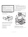
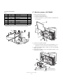
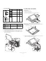
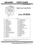
6) Remove the Top cabinet 6.
Precautions
a) Release the latches a, b and c in that order. Slide the upper
cabinet to the right and release the latch on the right.
• Before installation, be sure to turn off the power.
• Use gloves to protect your hands from being cut by the angle and
the chassis.
b) Lift the top cabinet and put it straight in the direction of arrow A.
( Be careful not to pull the cable between the LCD I/F PWB-Key
pad PWB of the top cabinet and the MAIN PWB of the Bottom
cabinet.)
• Connect all the cables securely. When connecting or disconnecting
the cables, be careful not to apply stress to the cables. (It may
cause disconnection.)
c) Pull and remove the following cables between the LCD I/F PWB
of the top cabinet and the MAIN PWB of the Bottom cabinet.
• Ground the human body to prevent against troubles and dust adhesion to the LCD by static electricity. When assembling the LCD, use
a discharge blower to prevent against dust intrusion.
• LCD Cable 7 : MAIN PWB-LCD unit : CN31
• Touch panel cable 8 : MAIN PWB-Touch panel PWB : CN34
• Be careful of the high voltage of the inverter PWB transformer.
• Key pad cable 9 : MAIN PWB : CN23
• Place the top cabinet with LCD panel side down, Please use a clean
dust free clothe to protect the touch panel and LCD area.
*Key pad : UP-C30PK is optional.
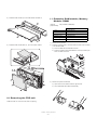
1. Removing the Rear display filter
2
1
1) Remove the two Screws 1.
2) Remove the Rear display filter 2.
A
2
5
6
5
a
b
1
8
9
2. Replacing the Rear display filter
c
7
Install the Rear display filter in the reverse order of removing.
3
4
3. Removing the Top cabinet
1) Remove the Screw 1.
4. Replacing the Top cabinet
2) Remove the Side cabinet 2.
3) Remove the Screw 3.
Install the top cabinet in the reverse order of removing. Before installing,
make sure that each connector is connected securely.
4) Remove the Printer lid 4.
5) Remove the two Screws 5.
UP-5900VI
Removing the Rear display filter
–1–
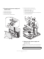
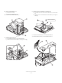
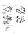
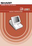
5. Removing the power supply unit
and AC cord
6) Remove the power supply unit and AC cord.
a) Remove the screw 7 and the earth wire 8.
b) Remove the four screws 9.
1) Remove the two screws 1.
c) Remove the power supply cover F.
2) Remove the AC cord cover 2.
d) Remove the power supply cable G.
3) Remove the three screws 3.
e) Use a minus screwdriver A to looser the AC cord fixing screws
(2 pcs.) of the power supply unit.
4) Remove the bottom plate 4.
f)
5) Remove the screw 5 and cable holder 6.
Remove the three screws H.
A
10
9
7
9
8
9
12
12
1
2
11
4
3
5
6
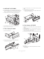
6. Replacing the power supply unit
and AC cord
Install the in the power supply unit and AC cord in the reverse order of
removing.
Before installing, make sure that each connector is connected securely.
*When connecting the AC cord to the power supply unit in assembly,
tighten with the torque of 3 kg/cm m1 kg/cm.
UP-5900VI
Removing the power supply unit and AC cord
–2–
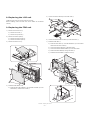
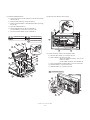
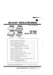
7. Remove the LCD unit
2) Remove the LCD rear cabinet 1.
1) Remove the LCD unit 1.
a) Remove the screw 2.
a) Remove the two Screws 2.
b) Remove the tilt cover 3.
b) Remove the pawls a to l of the LCD rear cabinet 1 in that
order.
c) Remove the screw 4 and cable holder 5.
d) Remove the core 6.
e) Remove the three screws 7.
g
f
e
d
2
c
h
3
i
b
1
j
a
k
l
2
7
7
4
1
5
6
Caution: Please do not place the LCD unit on hard surfaces, take special care not to place the LCD unit on any surface that may
cause damage to the unit.
UP-5900VI
Remove the LCD unit
–3–
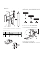
3) Remove the Inverter PWB 1.
5) Remove the LCD 1.
a) Remove the Inverter cable 2.
a) Remove the six screws 2.
b) Remove the CCFT cable 3.
b) Remove the two screws 3.
c) Remove the screw 4.
c) Remove the LCD plate 4.
d) Remove the Inverter cover 5.
d) Remove the screw 5 and LED PWB 6.
4
3
5
5
6
5
2
3
1
2
2
2
4
3
2
2
1
2
a
b
4) Remove the Touch panel PWB unit 1.
b
a) Remove the LCD cable(40P) 2.
a
b) Remove the Touch panel cable 3.
c) Remove the Inverter cable 4.
d) Remove the LED cable 5.
e) Remove the two Screws 6.
f)
Remove the LCD cable (29P) 7.
Lock
Unlock
*Reference for attaching LCD GUM A : a to LCD GUM B : b
a
b
6
7
2
6
b
5
1
3
a
4
LCD
ine
el
c
ren
fe
Re
Re
fer
e
nc
UP-5900VI
Remove the LCD unit
–4–
el
ine
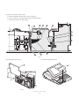
5) Connect the FDD CABLE I to the FDD UNIT G.
8. Replacing the LCD unit
12
11
10
Install the LCD unit in the reverse order of removing.
Before installing, make sure that each of the cables are connected
securely.
8
9. Replacing the FDD unit
9
1) Remove to the Printer lid 1.
a) Remove the screw 2.
8
b) Remove the printer lid 1.
12
2) Remove the bottom plate 4.
13
a) Remove the three screws 5.
6) Connect the FDD POWER CABLE 9 to the FDD UNIT G.
b) Remove the bottom plate 4.
3) Remove the FDD cover 7.
7) Install the FDD UNIT G.
a) Install the FDD UNIT G and FDD ANGLE-B J to the bottom
cabinet with the four screws K.
1
b) Connect the FDD CABLE I to the Main PWB.
c) Connect the FDD POWER CABLE 9 to the main PWB.
d) Pass the EARTH WIRE F through the hole A.
e) Install the EARTH WIRE F with the screw L.
2
11
14
7
4
15
10
13
15
9
A
5
4) Install the FDD ANGLE-A 8.
16
a) Install the two FDD ANGLE-A 8 and EARTH WIRE F to the
FDD UNIT G with the four screws H.
UP-5900VI
10
Replacing the LCD unit
–5–
8) Install the FDD COVER M to the FDD FRONT COVER N.
11. Extention RAM module, Memory
Module: DIMM
1 8
[Device]
168 pin DIMM (128Mbytes)
[Specification]
168pin.DIMM
1 7
Type
SD-RAM type
Access time
PC100 (more than)
Power
3.3V
Refresh cycle
4096/64 msec.
Refresh type
AUTO
Power consumption
1400 mA (less than)
1) Remove the top cabinet.
9) Install the FDD COVER UNIT M, N to the bottom cabinet.
2) Install the option D-RAM 1 to the D-RAM connector: CN13 (CN14)
2 on the Main PWB.
a) Insert a D-RAM into the D-RAM connector.
b) Push the D-RAM until the D-RAM disk is correctly locked by the
arms of D-RAM connector.
1
2
17
18
3) Remove the option D-RAM disk.
a) Open the arms of D-RAM connector right and left.
b) The D-RAM disk will be lifted automatically.
10. Removing the FDD unit
Install the FDD unit. In the reverse order of replacing.
UP-5900VI
Removing the FDD unit
–6–
3) Connect the display cable 4 to the connector: CN22 on the Main
PWB.
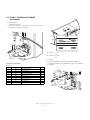
12. MCR UNIT: UP-E12MR2
4) Install the Display unit 5 to the cabinet
1) Fix the MCR ANGLE 1 to the lower cabinet with two screws 2.
a) Align the positioning boss A of the bottom cabinet with the
angle hole A in the display unit.
2) Connect the MCR cable 3 to the MCR connector with the cable
holder 6, and tighter the screw 7 on the back of lower cabinet.
3) Install the ferrite Core 4 to the MCR cable and GND wire 5.
4
5
A
1
A
4
6
A
2
3
5
7
14. Pole display: UP-P20DP
4) Fix the earth wire 5 from the UP-E12MR2 with the screw.
1) Install the core 6 to the display cable 1 and the display earth
cable 4.
5) Attach the rubber foot in Main Unit.
13. Rear display UP-I20DP
2) Connect the Display cable 1 to the remote display connector on
the back of the set.
1) Remove the Display filter 1.
3) Fix the display cable 1 with the cable holder 2, and tighten the
screw 3 on the back of bottom cabinet.
4) Fix the display earth cable 4 to the main chassis with the screw 5.
1
5
4
m
in
th
Wi
5c
2) Remove the Rear cover angle 2 from the Display filter 1
3
a) Remove the two Screws 3.
6
1
1
2
*Cable holder 2.
Use the following type of cable holder supplied with the UP-P20DP.
2
• “3N” (large type)
3
UP-5900VI
MCR UNIT: UP-E12MR2
–7–
* How to Extend Display Pole
5) Remove the two screws 6.
The pole can be extended by installing the attached pole to the standard pole.
6) Remove the Base cabinet 4 from the pole cabinet 7.
COMPONENT LIST:
No.
7, G
NAME
USE
7
Q’ty
Pole cabinet
Pole extension
2
H
Screw (M3 u 4)
Pole connection
4
I
Screw (M4 u 16)
Securing the UP-P20DP to the
wooden table
4
J
Screw (M4 u 20)
Securing the UP-P20DP to the
metal table
4
K
Nut
Securing the UP-P20DP to the
metal table
4
L
Display cable (S)
This display cable (S) should be
used instead of the standard
cable and earth wire if the UP20DP’s standard pole is
removed to lower the height of
the UP-20DP.
1
M
Earth wire (S)
4
1
6
1) Remove the five screws 1.
2) Remove the Base angle 2.
7) Pull the Ratchet 9 attached to the pole cabinet 7 out of the Display unit 8 by turning it as shown in Figure.
3) Remove the PWB unit 3 from the Base cabinet 4.
4) Remove the display cable 5 from the PWB unit 3.
8) Remove the two screws F.
9) Remove the pole cabinet 7 from the Ratchet 9.
Pattern side(PWB)
4
8
Core
10
2
9
1
7
10
9
3
1
5
UP-5900VI
Pole display: UP-P20DP
–8–
*Lowering the height of the UP-P20DP
10) Install the attached pole cabinet G to the pole cabinet 7 to fix it
with the screw H.
Remove the standard Pole and attach the Base cabinet 4 to the
Ratch 9. At this time, replace the standard Display cable and the
Earth wire with the S type cable L and wire M.
7
Display cable
7
12
12
12
12
15. Drawer unit: ER-03DW/04DW
11
11
1) Connect the drawer cable 1 to the drawer connector 2.
11) Install the pole cabinet G in the opposite order of the disassembly.
12) Fastening on the table:
Secure the Base cabinet 2 using the screw.
B
No.
NAME
USE
Q’ty
I
Screw (M4 u 16)
Securing the UP-P20DP to the
wooden table
4
J
Screw (M4 u 20)
Securing the UP-P20DP to the
metal table
4
K
Nut
Securing the UP-P20DP to the
metal table
4
A
7
6
2
1
5
2) Install the ferrite Core 5 to the drawer cable.
3) Fix the drawer cable 1 with the cable holder 6, and tighten the
screw 7 on the back of lower cabinet A or B.
UP-5900VI
Drawer unit: ER-03DW/04DW
–9–
16. COM1, COM2 and COM3/5
Connector
1) COM1 & COM2
• D-SUB 9pin Connector
• CI signal of COM1 or COM2 and +5V power supply can be
switched in order to supply +5V power.
S2
S1
+5V
+5V CI
1
3
S2
m
in
th
Wi
3c
COM1
+5V CI
1
3
COM2
S1
CI
+5V CI
1
3
S2
+5V CI
1
3
S1
S2 = COM1: 1 = +5V
3 = CI
S1 = COM2: 1 = +5V
3 = CI
CORE(RCORF6700BHZZ)
Wire band
2) COM3/5
• Channels of COM port with an RJ45 connector are equipped.
• Two CABLE HOLDER 1 and SCREW (M3 u 8) 2 are contained in
the package.
Connector Specifications*
D-SUB9
Pin No.
Signal
1
CD
Data Carrier Detect
Function
I/O
I
2
RD
Receive Data
I
3
SD
Send Data
O
4
ER
Data Terminal Ready
O
5
SG
Signal Ground
—
6
DR
Data set Ready
I
7
RS
Request to Send
O
8
CS
Clear to Send
I
9
CI/+5V
Ring Indicate/+5V
m
in
th
Wi
5c
2
1
I/–
CORE(RCORF6700BHZZ)
Wire band
UP-5900VI
COM1, COM2 and COM3/5 Connector
– 10 –
17. Built-in printer: UP-T80BP
Connector Specifications*
RJ45
Function
I/O
1) Remove the BOTTOM PLATE 2.
Pin No.
Signal
1
RS
Request to Send
O
a) Remove the three SCREWs 1.
2
ER
Data terminal Ready
O
b) Remove the BOTTOM PLATE 2.
3
SD
Send Data
O
4
SG
Signal Ground
—
c) Remove the SCREW 3, CABLE CLAMP 4 and POWER SUPPLY CABLE 5.
5
SG
Signal Ground
—
6
RD
Receive Data
I
7
DR
Data set Ready
I
8
CS
Clear to Send
I
2
3) LAN, USB
• LAN with an RJ45 connector and USB connector are equipped.
1
3cm
RCORF6699BHZZ
4
3
5
Fig. 1
2) Install the PS+CONTROL PWB 6.
a) Fix the PS+CONTROL PWB 6 with three SCREWs 7, Z, 3
*SCREW 3: Use the screw which was fixing the CLAMP 4.
3) Connect the POWER SUPPLY CABLE 5 to the PS+CONTROL
PWB 6. (No. CN1)
4) Connect the I/F CABLE 8 of the PS+CONTROL PWB 6 to the
MAIN PWB (No.CN109)
8
30
5
3
7
30 : XEBSD30P08000
6
7 : XHBSD30P06000
Fig. 2
UP-5900VI
Built-in printer: UP-T80BP
– 11 –
8) Install the AUTO CUTTER RELAY PWB UNIT J.
5) Remove the PRINTER LID 9.
a) Install the AUTO CUTTER RELAY PWB UNIT J with SCREW
K.
a) Remove the screw F.
b) Remove the PRINTER LID 9.
b) Pass the AUTO CUTTER RELAY PWB CABLE L through the
hole (C).
6) Install the PAPER ROLLERs (4ea.) G.
9
11
15
15 : XEBSD30P08000
16
C
14
Fig. 5
9) Install the PAPER GUIDE M to the PRINTER UNIT N.
10
10) Install the HEAD CABLE O to the PRINTER UNIT N.
Fig. 3
7) Install the SWITCH UNIT H.
a) Fix the SWITCH UNIT H on the cabinet pawl A.
b) Pass the SWITCH UNIT CABLE I through the hole (B).
17
19
12
12
A
13
B
A
Fig. 4
18
Fig. 6
UP-5900VI
Built-in printer: UP-T80BP
– 12 –
11) Install the PRINTER UNIT N.
12) Wiring for each cables as shown below.
a) Connect the AUTO CUTTER CABLE P to the AUTO CUTTER
RELAY PWB J.
b) Pass the HEAD CABLE O through the hole (C).
c) Pass the MOTOR CABLE Q and SENSOR CABLE R through
the hole (D).
d) Open the PRINTER UNIT N.
e) Fix the PRINTER UNIT N with four SCREWs S.
Fix the SCREWs S in the order of S-(a) to S-(d).
f)
20
Fix the two EARTH WIREs T with a SCREW U.
23
a : XEBSD26P06000
23
b : XEBSD26P06000
23
c : XEBSD26P08000
23
d : XEBSD26P08000
14
25 : XHBSD30P06000
23
23
c
23
a
d
18
16
13) Connect the Printer cables to the CONTROL PWB.
25
a) SWITCH UNIT CABLE I: Connect to the CN7.
24
23
b
b) HEAD CABLE O:Connect to the CN5.
Attach the FERRITE CORE (L size) V and
CABLE CLAMP 4.
Fix the CABLE CLAMP 4 with a SCREW X.
22
19
21
20
19
c) AUTO CUTTER RELAY PWB CABLE L: Connect to the CN4.
C
d) MOTOR CABLE Q: Connect to the CN2.
e) SENSOR CABLE R: Connect to the CN6.
28 : XEBSD30P08000
D
14
16
Fig. 7
28
4
26
16
21
19
13
22
Fig. 8
UP-5900VI
Built-in printer: UP-T80BP
– 13 –
14) Wiring for each cables as shown below.
a) Attach the FERRITE CORE (S size) Y to the I/F CABLE 8.
b) Fix the I/F CABLE 8 and EARTH WIRE [ with the CABLE BAND Z.
c) Set the switch: SW2 to the “MRS” position.
16
21
28
27
26
8
29
31
30
SW2
13
22
19
Fig. 9
15) Install the BOTTOM PLATE 2.
16) Install the PRINTER COVER Y.
2
29
1
Fig. 11
Fig. 10
UP-5900VI
Built-in printer: UP-T80BP
– 14 –
18. KEY PAD: UP-C30PK
1. LIST FOR SCREWs
No.
PARTS CODE
M [mm]
L [mm]
K
XEBSD30P08000
3
8
*Opetion for KB.
Standard for TQ, TS, KA
Z
X
S-a
L
1) Remove the upper cabinet.
XEBSD26P06000
2.6
6
XEBSD26P08000
2.6
8
XHBSD30P06000
3
8
2) Remove the keyboard lid 1 from the upper cabinet.
S-b
S-c
M
S-d
7
U
1
L
M
2. INSTALLATION OF PAPER NEAR END SENSOR
[PARTS LIST]
No.
PARTS NAME
PARTS CODE
*Keyboard lid 1 is tightly engaged and hard to be removed.
When removing it, use nippers to cut off four pawls A from the back of
the upper cabinet.
NOTE
1
PAPER NEAR
END SENSOR
DUNTK3819BHZZ
SENSOR UNIT,
FIXING SCREW
2
NEAR END
SENSOR
CONNECTOR
QCNCM6865RC0B
2 pin connector
B a c k o f th e u p p e r c a b in e t
P a w ls A
P a w ls A
1. Remove the BOTTOM PLATE .
2. Remove the PS+CONTROL PWB .
P a w ls B
3. Solder the CONNECTOR 1 to the PS+CONTROL PWB (No. CN1)
4. Install the NEAR END SENSOR UNIT 2 to the CABINET , and fix it
with the fixing SCREW 3.
P a w ls B
3) Attach the keyboard cover 2 and keyboard unit 3 to the upper
cabinet, and fix them with four screws 4.
2
3
2
1
3
4
Fig. 12
UP-5900VI
KEY PAD: UP-C30PK
– 15 –
4
*When attaching keyboard cover 2, engage pawls C and D securely
with the upper cabinet.
5) Connect the cable of the keyboard unit 3 to the main PWB connector CN23.
B a c k o f th e u p p e r c a b in e t
P a w ls D
P a w ls C
How to wire cables :
4) Run the cable along the mark-off line of the cabinet and secure it at
two points with clamps.
Clamp mounting location diagram
Pay attention to the
direction of adherence.
Remove release paper.
6) Attach the earth spring 5 to the lower cabinet with the screw 6.
6
5
Reference line for attaching CLAMP.
90mm
22mm
70mm
<REFERENCE FOR FOLDING FLAT CABLE>
FLAT CABLE (480mm)
Reinforcement plate
UP-5900VI
KEY PAD: UP-C30PK
– 16 –
q
COPYRIGHT 2002 BY SHARP CORPORATION
All rights reserved.
Printed in Japan.
No part of this publication may be reproduced,
stored in a retrieval system, or transmitted.
In any form or by any means,
electronic, mechanical, photocopying, recording, or otherwise,
without prior written permission of the publisher.
SHARP CORPORATION
Digital Document Systems Group
Products Quality Assurance Department
Yamatokoriyama, Nara 639-1186, Japan
2002 May Printed in Japan t