1
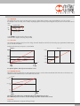
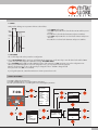
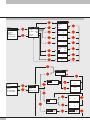
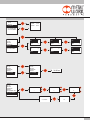
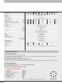
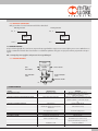
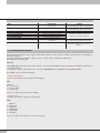
REGTRONIC
OPERATING INSTRUCTIONS
1. FEATURES
• Electrical connection: M12 8-pin connector.
• Preset pressure range 0.05-10 bar with possible full scale and minimum pressure regulation.
• 10–100 mbar adjustable deadband.
• Supply pressure: FS+ at least 1 bar, max 11 bar.
• 24Vdc power supply.
• IP65 index of protection.
• LED indicating pressure achieved and digital output active.
• Graphical display and keypad to display the pressure, unit of measurement and parameter setting.
• 0-10 V analog output signal.
2. SETTING
NB: parameter changes can also be effected through the software downloadable from the website www.metalwork.eu
In the version with the display, Press OK and ESC together to access the setting menu.
Select the parameter using the arrow keys.
Press ESC to return to the previous page.
m During setting, pressure regulation is NOT active.
2.1 DISPLAY
2.1.1 LANGUAGE
Italiano
English
Deutsch
Español
Français
• Select LANGUAGE using the arrow keys, then press OK.
• Select the desired language using the arrow keys, then press OK.
2.1.2 UNIT OF MEAS
bar
psi
MPa
• Select UNIT OF MEAS. using the arrow keys, then press OK.
• Select the desired unit of measurement using the arrow keys, then press OK.
• Manual display contrast adjustment
• Select CONTRAST using the arrow keys, then press OK.
• Select the value using the arrow keys, then press OK.
• Compensation as a function of temperature is automatic.
2.1.3 CONTRAST
2.2 SET UP
2.2.1 INPUT
0 / 10 V
0/5V
4 / 20 mA
RS232
Keypad
• Select INPUT using the arrow keys, then press OK.
• Select the type of input using the arrow keys and then press OK.
• For the type of analog input (0/10V-0/5V-4/20mA), use an appropriate analog signal.
• For the type of RS232 input, use the communication protocol described in chapter 12.
• For the type of keypad input, set the pressure value using the arrow keys. When you press the display buttons, the set pressure appears; when you release them, the preset pressure is displayed.
2
2.2.2 DEADBAND
This indicates the pressure range in proximity to the set pressure, within which regulation is active. The deadband is + and - the set value.
It is advisable to enter low values, 10 or 15 mbar, only if high regulation accuracy is required. High accuracy involves more work for the solenoid valves.
+ BM
Regolation ON
SET
Regolation OFF
- BM
Regolation ON
• Select DEADB using the arrow keys, then press OK.
• Enter the value using the arrow keys, then press OK.
2.2.3 FULL SCALE
This indicates the maximum preset pressure. The analog command is divided over the Full Scale. The analog output signal indicates that the preset pressure is 0-10V for 0-10 bar.
Examples with maximum preset pressure 3, 5 and 10 bar
Full Scale
Fondo
Scala
Analog
Out
Out
analogico
10 [bar]
10 [bar]
5 [bar]
5 [bar]
3 [bar]
3 [bar]
0 [bar]
Set
0 [V]
0 [V]
4 [mA]
0 [bar]
10 [V]
5 [V]
20 [mA]
0 [volt]
3 [volt]
5 [volt]
10 [volt]
For optimal regulation, the feed pressure must be FS + 1 bar.
2.2.4 MINIMUM PRESSURE
Indicates the minimum regulated pressure with set 0V (4 mA). The value can be set between 0 and 50% of the Full Scale set. The reference set is divided between the Minimum Pressure value and the Full Scale value.
Full Scale
100% [FS]
set
50% [FS]
set
[FS]
set 0 [V]
0 [V]
4 [mA]
Set
10 [V]
5 [V]
20 [mA]
The minimum value which can be set with Keyboard Set is the Minimum Pressure value.
If the “Minimum pressure” function is used, the “Analogue input filter” function must be set to 0.
2.2.5 RS232
Enables serial transmission, irrespective of the type of input.
3
2.2.6 REGULATION SPEED
It allows to modify the response speed of the regulator
SET
SET
V=5 fast regulation
V=1 slow regulation
2.2.7 ANALOGUE INPUT FILTER
The analogue input filter can be used to set an offset value on the analogue signal. The pressure is kept to 0 until the offset value is reached.
In this way, it is possible to filter any unwanted noise or small signals from analogue boards, which would cause undesired small and continuous pressure regulations. The setting ranges from 0 to 30 and corresponds to an offset of 0-110 bar, 0-110 mV and 4-4.25 mA.
The default value is 2, which corresponds to 25 mbar.
2.3 DIGITAL OUTPUT
Two digital outputs are available, one PNP and one NPN. They can be configured independently as normally open or normally closed. The P ON (P+) and P OFF (P-) activation/deactivation thresholds are unique.
2.3.1 PRESSURE SWITCH CONFIGURATION (P)
• Select OUTPUT using the arrow keys, then press OK.
• Select CONFIGUR. to select the operating mode, then press OK.
P ON
• Select PRESSURE SWITCH, then press OK. PRESSURE SWITCH mode, shown with CONFIGUR. P. has been selected.
P OFF
• Use the arrow keys to select PRESSURE SWITCH and press OK.
• Select P ON and press OK. Enter the desired activation pressure and press OK.
• Select P OFF and press OK. Enter the desired deactivation pressure and press OK.
ON
• Press ESC to exit the menu.
OFF
2.3.2 SET (S) REFERENCE
This function can be used to make a “variable” setting for the pressure switch.
Out is activated when the preset pressure is reached, with a tolerance defined by P+ and P-.
OUT OFF
SET
OUT ON
OUT OFF
P+
PRESSURE
P-
• Select OUTPUT using the arrow keys, then press OK.
• Select CONFIGUR. to select the operating mode, then press OK.
• Select SET. REF and press OK. SET REFERENCE mode, shown with CONFIGUR. S. has been selected.
• Use the arrow keys to select PRESSURE SWITCH and press OK.
• Select SET.REF and press OK.
• Select P+ and press OK.
• Enter the upper tolerance pressure and press OK.
• Select P- and press OK. Enter the lower tolerance pressure and press OK.
• Press ESC to exit the menu.
2.3.3 TYPE OF CONTACT
This function is used to identify whether the digital output is normally open or normally closed.
• Select TYPE OF CONTACT and click OK.
• Select TYPE PNP or TYPE NPN, click OK and enter the type of contact.
• Click ESC to exit.
2.4 DATABASE
Serial number
Software version
Hour counter: indicates the operating time in hours.
4
2.5 DEBUG
Utility used for checking correct operation of the two solenoid valves.
•Select DEBUG and press OK.
P IN
• Select PIN and press OK. The in solenoid valve activates and the pressure increases.
• Press OK. The in solenoid valve deactivates and pressure stabilizes.
P OUT
• Select POUT and press OK. The out solenoid valve activates and pressure decreases.
bar
• Press OK, the out solenoid valve deactivates and pressure stabilizes.
P
2.6 PASSWORD
This is a three-digit code used to protect the set configuration.
• Select SET PASSWORD with the arrow keys and click OK. On the setting page, use the arrow keys to enter the desired value and click OK to
confirm. The system then displays the confirmation message “PASSWORD SAVED”.
• Select PASSWORD and click OK to enable/disable the function. If the password set to ON, it prevents access to the configuration menu.
When you press OK+ESC together to access the configuration menu, you are prompted to enter the password.
Enter the saved password. You can use the arrow keys to change the value or click OK to change the field.
If the password is set to OFF, it is not enabled.
If you forget the password, contact the manufacturer to obtain a password reset code.
3. ACCESS TO THE MENU
• Press OK to display the set parameters.
• Press OK and ESC together to access the parameter setting menu.
• Use the up and down arrows to scroll through the menu and modify the parameters.
ESC
7.00
bar
OK
PRESSURE
OUT
ESC
OK
DISPLA Y SET
PARAMETERS
INPUT
UNIT MEAS .
OUTPUT
DEAD BAND
F SCAL E
MIN. PRESS.
LANGUAGE
T=
PC
SERIAL NO
SW VERS
0/10 V
BAR
P
0.05 0
7.5
0.000
ITA
40.5°C
ON
00100
03.01
ESC
OK
ITALIANO
GERMAN
ENGLISH
SPANISH
FRENCH
ESC
SET UP
ESC
+
DISPLA Y
OK
SET UP
OUTPUT
DATABASE
DEBUG
PASSWORD OFF
SET PASSWORD
OK
bar
LANGUAGE ENG
UNIT MEAS. BAR
CONTRAST 40
ESC
OK
OK
MPa
PSI
CONTRAST
40
OK
ESC
5
3. ACCESS TO THE MENU
OK
0/10V
0/5V
4 / 20 mA
RS232
KEYPAD
OK
DEAD BAND
0.050
bar
OK
OK
F.SCAL E
10.0
OK
ESC
DISPL AY
SET UP
OUTPUT
DATABASE
DEBUG
PASSWORD OFF
SET PASSWORD
OK
ESC
INPUT
0/10 V
DEAD BAND 0.050
F. SCALE
10.0
MIN. PRESS. 0.000
PC
ON
4
SPEED ADJ
OFFSET 0
02
OK
bar
MIN. PRESS. 0.000
OK
OK
INPUT
0/10 V
DEAD BAND 0.050
F. SCALE
10.0
PC
OFF
OK
OK
OK
SPEED ADJ
4
OK
OK
OFFSET 0
02
OK
OK
PRESS.SWITCH
RIF. SET
OK
ESC
DISPL AY
SET UP
OUTPUT
DATABASE
DEBUG
PASSWORD OFF
SET PASSWORD
PON
POFF
OK
ESC
PON
7.0
5.0
OK
CONFIGUR.
PRESS.SWITCH
RIF. SET
CONTACT TYPE
P
POFF
OK
5.0 bar
OK
OK
P+
P-
P1.0
2.0
1.0
ESC
bar
P+
OK
OK
TYPE PNP
TYPE NPN
6
7.0 bar
OK
NO
NO
OK
2.0
TYPE PNP
TYPE NPN
bar
NC
NO
ESC
DISPL AY
SET UP
OUTPUT
DATABASE
DEBUG
PASSWORD OFF
SET PASSWORD
ESC
SERIAL NO
SW VERS.
H.-METER
00010
03.01
00001
OK
ESC
DISPL AY
SET UP
OUTPUT
DATABASE
DEBUG
PASSWORD OFF
SET PASSWORD
DISPLA Y
SET UP
OUTPUT
DATABASE
DEBUG
PASSWORD OFF
SET PASSWORD
DISPLA Y
SET UP
OUTPUT
DATABASE
DEBUG
PASSWORD OFF
SET PASSWORD
PIN
0
POUT
0
PIN
0
POUT
0
OK
PIN
1
POUT
0
PIN
0
POUT
1
OK
PIN
0
POUT
0
PIN
0
POUT
0
OK
OK
ESC
DISPLA Y
SET UP
OUTPUT
DATABASE
DEBUG
PASSWORD ON
SET PASSWORD
OK
OK
PASSWORD
OK
---
OK
10.00 bar
PASSWORD
OK
1--
PASSWORD
123 SALVATA
PASSWORD
OK
PASSWORD
OK
12 -
OK
123
7
4. TECHNICAL DATA
Threaded port
Fluid
MIN inlet pressure
MAX inlet pressure
Temperature range
Pressure regulation range
Flow rate at 6.3 bar ∆P 0.5
Flow rate at 6.3 bar ∆P 0.1
Exhaust flow rate at 6.3 bar with 0.1 bar overpressure
Exhaust flow rate at 6.3 bar with 0.5 bar overpressure
Weight
Class of protection
Power supply
Input signal (input impedence)
bar
bar
°C
bar
Nl/min
Nl/min
Nl/min
Nl/min
kg
Voltage
Current
Serial ports
Manual
Analog
Digital
Output signal
Linearity
Hysteresis
Repeatability
Sensitivity/Dead-band
Output pressure (display version)
REGTRONIC
REGTRONIC
REGTRONIC
NEW DEAL
300
400
M5
1/8’’
1/4’’
3/4’’
1’’
1/2’’
3/4’’
1’’
1’’
1 1/4’’ 1 1/2’’
2’’
Filtered, unlubricated air. The air must be filtered at least 10 µm
Regulation pressure +1 bar
11
0 ÷ 50
0.05 ÷ 10 (settable full scale and minimum pressure)
10
770
1490
10000
4500
18000
20000
10
1050 1700
13000
7000
2
320
500
1800
250
400
400
9
650
1200
2000
500
850
850
0.2
0.38
0.38
1.3
1.5
5
5.8
65
24 Vcc +10% -5% I max 110 mA
0 ÷ 5 Vcc, 0 ÷10 Vcc (approx. 168 KΩ)
4 ÷ 20 mA (approx. 100 KΩ)
RS 232
Keypad
0 ÷ 10 Vcc (1 V=1bar) - 1 mA max
PNP open collector output: max 24V 60 mA
NPN open collector output: max 24V 60 mA
≤ ± 0,5% (Full scale)
≤ ± 0,2% (Full scale)
≤ ± 0,2% (Full scale)
setting range 10 ÷ 100 mbar
≤ ± 0,3% (Full scale)
bar, MPa, psi
0.01 bar - 0.001 MPa - 0.01 psi
≤ ± 0,4% (Full scale)
max 2 mbar / °C
volume 100 cc
volume 1000 cc
0.5
0.2
0.3
0.45
0.35
0.55
0.3
0.3
0.45
0.7
In any position
The features shown refer to the static condition only. With air consumption on the output side, the pressure may vary
REGTRONIC
Accuracy
Unit of measurement
Minimum resolution
Analog output accuracy
Temperature characteristics
Response time with ∆P =1 bar
from 6 to 7 bar
from 7 to 6 bar
Installation position
Notes
s
s
5. INSTALLATION AND OPERATION
5.1 PNEUMATIC CONNECTION
Pneumatic connection is via the threaded holes in the body.
It is important for the regulator pressure not to exceed 11 bar and the compressed air to be filtered at 10 µm and dried, to prevent impurities or
excessive condensate from causing a malfunction.
The supply pressure must always be higher than the preset pressure.
The regulator pressure must be at least 1 bar higher than the full scale value.
If a silencer is mounted on the outlet, the flow rates and response times may vary. Check the silencer periodically for clogging and replace if necessary.
5.2 ELECTRICAL CONNECTION
This is by means of M12 female circular 8-pin connector (to be ordered separately).
Refer to the wiring diagram below.
Wrong connections may permantenly damage the regulator.
5.2.1 CONNECTOR PIN CONFIGURATION
1 = TX (RS232)
2 = RX (RS232)
3 = set 0-10 V / 0-5 V / 4-20 mA
4 = digital out 0-24 V NPN
5 = analog out 0-10 V
6 = digital out 0-24 V PNP
7 = 0 V (GND)
8 = power supply +24V 8
(WHITE)
(BROWN)
(GREEN)
(YELLOW)
(GREY)
(PINK)
(BLUE)
(RED) colours’ sequence in compliance with Metal Work prewired connectors.
2
3
1
7
8
4
5
6
Regulator connector
viewed from above
5.2.2 DIGITAL OUT CONNECTION
Utility per verificare il corretto funzionamento delle due elettrovalvole
NPN Digital OUT
PNP Digital OUT
Pin 6
Pin 4
LO AD
LO AD
0 V
+ 24 V
5.3 OPERATING PRINCIPLE
Using a software algorythm, the control circuit compares the input signal with the output pressure measured by the pressure sensor. When there is a
change, it activates the inlet and outlet solenoid valves to re-establish an equilibrium. This gives an output pressure that is proportional to the input
signal.
N.B.: removing the power supply, the outlet pressure doesn’t get discharged
5.3.1 FUNCTION DIAGRAM
DISPLAY
FEED
OUTPUT SIGNAL
CONTROL
CIRCUIT
INPUT SIGNAL
INLET SOLENOID
VALVE
OUTLET SOLENOID
VALVE
P
IN
PRESSURE SENSOR
OUT
6. TROUBLESHOOTING
PROBLEM
The display does not come on
The unit does not respond or responds wrongly to the setpoint
The unit does not reach the desired pressure
The display shows an unreal value
The display is difficult to read
The unit adjusts continually
POSSIBLE CAUSES
SOLUTION
No 24V power supply
Check the power supply, make sure it is
enough and check the wiring is in accordance
with the wiring diagram
Wrong input signal configuration
Configure the appropriate type of input from the menu
Check the signal wire is connected to the right
pin
Setpoint too low
Provide a suitable setpoint
The full-scale setting is at a lower pressure
than desired
The supply pressure is too low
Wrong unit of measurement
Poor contrast
Air leak in the circuit after the unit
Continuous variation in volume Other problems
Deadband too small
Contact the manufacturer
Set the full scale correctly
Increase the supply pressure
Check the unit of measurement
Adjust the contrast
Eliminate the leak
Normal behaviour; the unit has to keep
adjusting the maintain the preset pressure
Increase the deadband
9
6.1 LIST OF ALLARMS
ALARM
+V NPN DOUT SHORT-CIRCUIT ALARM
0V PNP DOUT SHORT-CIRCUIT ALARM
LOW VDC ALARM
0V P. INP SHORT-CIRCUIT ALARM
0V P. OUT SHORT-CIRCUIT ALARM
P. INP DISCONNECTED ALARM
P. OUT DISCONNECTED ALARM
ANALOG SET ALARM
PRESSURE OUT OF RANGE ALARM
POSSIBLE CAUSES
SOLUTION
NPN output to power supply unit has
Eliminate the cause of the shortcircuit. Switch
shortcircuited
the unit off and back on again to reset the alarm.
PNP output to earth has shortcircuited
Eliminate the cause of the shortcircuit. Switch
the unit off and back on again to reset the alarm.
Supply voltage below 21V
Increase to a sufficient voltage
Supply solenoid valve has shortcircuited
Drain solenoid valve has shortcircuited
Switch the unit off and back on again. If the
Fill solenoid valve disconnected
alarm persists, contact the manufacturer.
Drain solenoid valve disconnected
Occurs with 4/20 mA input when the current
Send the unit a correct input signal. Switch
exceeds 23mA
the unit off and back on again the reset the alarm.
Downstream pressure exceeds 10200 mbar
Check to see if the drain is blocked. The alarm resets automatically when the pressure drops below the threshold.
7. SERIAL COMMUNICATION PROTOCOL
Communication protocol can be used to configure and control the regulator via an PC serial port. To activate serial communication, set the RS232 to
ON on the set-up page.
The communication protocol is 2400 8 N 1 (8 bits, no parity, 1 stop bit) and the commands are in ASCII format.
All commands are the following type:
ESCcnnnnn
Where ESC (Escape) prepares the unit to receive commands, c is the command and nnnnn is the associated parameter, the length of which depends
on the actual command.
For example, the control to regulate the pressure to 1 bar must be ESCP01000, which in ASCII-HEX becomes 1B503031303030.
The available controls are shown herewith below.
• Set Unit of measurement
Sets the unit of measurement. The command is the following type:
ESCcn
Where n =
0 = pressure in bar
1 = pressure in MPA
2 = pressure in psi
If n is not one of these values, the unit does not change.
• Set type of input
Sets the type of control.The command is the following type:
ESCdn
0
1
2
3
4
Where n =
= 0-10V input
= 0-5V input
= 4-20mA input
= keypad input
= serial input
If n is not one of these values, the type of control does not change
10
• Set Deadband
Sets the deadband. The command is the following type:
ESCbnnn
Parameter nnn must always be 3 digits. The value must be expressed in mbar.
• Set Full Scale
Sets the full scale. The command is the following type:
ESCEnnnnn
Parameter nnnnn must always be 5 digits. The value must be expressed in mbar
(e.g. ESCE7000, the set full scale is 7000 mbar)
• Minimum pressure set
Set the minimum regulated pressure with set 0.
The maximum value which can be set is the 50% of the FS. The control is type:
ESCennnnn
The parameter nnnnn must be always defined on 5 figures. The value must be expressed in mbar
(For example, ESCe01000, the minimum pressure is set at 1000 mbar)
• Digital output configuration
Sets the type of digital output and the activation/deactivation values. The command is the following type:
ESCO1sssssxxxxx
Where:
1 = type of output (0 = pressure switch 1 = reference)
sssss = output activation threshold
xxxxx = output deactivation threshold
Parameters s and x must always be 5 digits. The value must be expressed in mbar.
• Set Pressure
Sets the pressure to reach. The command is the following type:
ESCPnnnnn
Parameter nnnnn must always be 5 digits. The value must be expressed in mbar
(e.g. ESCP01001, the set pressure is 1001 mbar)
• Read preset pressure
Displays the preset pressure value. This command requires no parameters.
It is the following type:
ESCp
The response is:
ESCpnnnnn
Parameter nnnnn represents the pressure in mbar (e.g. ESCp05600, the preset pressure is 5.60 bar)
11
• Read configuration
Displays a string with complete module configuration. This command requires no parameters.
It is the following type:
ESCi
The expected response is:
ESCi05322b050c0d2E10000O10500002000e01000
Where:
05322 = the pressure reading
050 = the deadband (b = the set deadband code)
0 = the unit of measurement (c = the set unit of measurement code)
2 = type of control (d = the set type of control code)
10000 = the full scale (E = the code)
1 = type of output (0 = pressure switch 1 = reference) (O = the code)
05000 = output activation threshold
02000 = output deactivation threshold
01000 = minimum pressure
The type of parameter is indicated before the value, except for pressure.
7.1 SERIAL CABLE CONNECTION DIAGRAM
M12 connector
12
9-pin D-Sub connector
PIN 1 (TX)
PIN 2
PIN 2 (RX)
PIN 3
OV
PIN 5