1
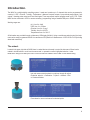
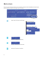
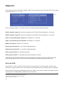
This manual contains safety information that if ignored
can endanger life or result in serious injury. They are
indicated by this icon.
Keep the instrument protected from sun and water.
Avoid water splashes.
OPERATING INSTRUCTIONS F O R
“ MAX5” INSTRUMENT
Read Carefully !
ENGLISH Version
1
R2-06-08
“MAX5” instrument complies with the following European regulations:
EN60335-1 : 1995, EN55014, EN50081-1/2, EN50082-1/2, EN6055-2, EN60555,3
Based on directive CEE 73/23 c 93/68 (DBT Low voltage directive) and directive 89/336/
CEE (EMC Electromagnetic Compatibility)
GENERAL SAFETY GUIDELINES
Danger! In emergencies the instrument should be switched off immediately! Disconnect the
power cable from the power supply!
When installing always observe local regulations!
Manufacturer is not liable for any unauthorized use or misuse of this product that
may cause injury, damage to persons and / or materials.
Caution! Instrument must be accessible at all times for both operating and servicing. Access
must not be obstructed in any way!
Instrument and accessories must be serviced and repaired by qualified and authorized personnel only!
Instrument must be operated / serviced by trained technicians only!
All connection operations must be performed while the instrument is not connected to main supply!
2
Introduction.
The MAX5 is a multiple digital controlling system. It reads and controls up to 5 channels that can be programmed to
control pH - ORP - Chlorine - Turbidity - Temperature. It features 6 setpoint outputs, 6 proportional pump outputs, 6 mA
outputs,1 cleaning probe output and 5 level tank inputs. Three way setpoint outputs program mode: on/off - PID - PWM.
MAX5 can be connected to a PC for remote controlling / programming using a standard USB port or RS485 connection.
Working ranges are:
pH : from 0 to 14pH
ORP: from 0 to 1000mv
Chlorine: from 0 to 10 mg/l
Turbidity: from 0 to 30 NTU
Temperature: from 0 to 200 °C
All information are provided through a widescreen LCD display (240x64). Using a revolutionary wheel control the instrument can be easily programmed. MAX5 is housed into an IP65 plastic box. Measures are: L325 x H235 x D125 (including
wheel and connectors).
The wheel.
Located in the upper right side of MAX5 there is a wheel that must be used to control the instrument. Wheel can be
rotated in both directions to scroll over the menus and / or pressed to confirm highlighted selection / value.
NOTE: Once changes are made press “OK” to save and exit from submenu. Press “ESC” to exit without saving.
Into main menu rotate the wheel to cycle-loop through all options.
Clockwise: setpoint --> Calibration --> Option --> Manual -->Exit
or Counterclockwise.
Press wheel to move on submenu for selected option.
3
Mainboard Connections.
Unplug instrument from main power supply then perform connections to probes and / or selected outputs by following the
above picture. For easy understanding board as been divided into two parts: Power connections and I/O connections.
For EClx series probes and NTU connections see APPENDIX A at page 30.
Block numbers are related only to its own part of the board.
L 1 2 3 4 5 6
E E E E E E E
1 2 3 4 5 6 7 8 9 10 11 12 13 14 15 16 17 18 19 20 21 22 23
F1 F2
NNNNNNNN
7 8 9
10 11 12
24 25 26 27 28 29 30 31 32 33 34 35 36 37 38 39 40 41 42 43 44 45 46
]
]
Power Connections
I/O Connections
Power Connections:
F1: Circuit fuse (3.15AT)
F2: General fuse (6.3AT)
Main power supply (from 115VAC to 240VAC):
L (live), E (earth), N(neutral)
Setpoint Outputs (from 115VAC to 240VAC):
1-E-N
2-E-N
3-E-N
4-E-N
5-E-N
6-E-N
(fuse protected on its own relay)
(fuse protected on its own relay)
(fuse protected on its own relay)
(fuse protected on its own relay)
(fuse protected on its own relay)
(fuse protected on its own relay)
Probe Cleaning output:
7(N.C.), 8(C), 9(N.O.)
General Alarm output:
10(N.C.), 11(C), 12(N.O.)
Warning: Connections must be perfomed by qualified and trained personnel only.
4
I/O Connections:
Proportional pump (mod. “IS” driven by pulses) outputs:
1(-) ; 2(+): Output P1
3(-) ; 4(+): Output P2
5(-) ; 6(+): Output P3
7(-) ; 8(+): Output P4
9(-) ; 10(+): Output P5
11(-) ; 12(+): Output P6
mA outputs:
13: Common
14: mA output 1
15: mA output 2
16: mA output 3
17: mA output 4
18: mA output 5
19: mA output 6
RS485:
20: GND
21: - Signal 485
22: + Signal 485
23: n/c
Tank Level inputs:
24 (-) ; 25 (+) Level 1
26 (-) ; 27 (+) Level 2
28 (-) ; 29 (+) Level 3
30 (-) ; 31 (+) Level 4
32 (-) ; 33 (+) Level 5
Proximity Sensor (mod. “SEPR”) input:
34(+ Brown) ; 35(Black) ; 36(- Blue)*
*shortcut with block n.32
For others uses (set flow option from setup menu)
34(+12VDC) ; 36(-12VDC)
Reserved [for testing purpose only]:
37 ; 38 ; 39
Temperature Probe input for mod. “PT100” only:
40(yellow) ; 41(brown) ; 42(white) ; 43(green)
Standby signal input:
44(+) ; 45(-)
Warning: Connections must be perfomed by qualified and trained personnel only.
5
Main screen.
From main screen all instrument fucntions can be reached by rotating the wheel and highlighting the selected option.
Options available are located in the low right corner of the screen.
fig. 1
Status control. Press
here to scroll through:
main menu alternate view
status of inputs - outputs - alarms
log entries
Setup menu. (passcode
Off menu.
Press here to turn off instrument
Alarm menu.
6
protected area)
Press here to stop alarms
Passcode.
From main screen rotate wheel until to highlight
then press wheel.
Note: This is a passcode protected area. For this reason every time this menu is reached, the instrument will ask for a
passcode as shown.
fig. 2
If this is a “first time visit” the default passcode is “0000” (both Administrator and User).
Just press four times the wheel. Otherwise rotate wheel to move through digits and press wheel to choose.
Rotate wheel to ESC and press wheel to go back to main screen without accessing setup menu.
Setup.
From main screen rotate wheel until to highlight
graph.
then press wheel. Enter passcode as described in previous para-
fig. 3
Rotate wheel to scroll through all options and press wheel to enter into menu of selected option.
Setpoint option.
Use this menu to define instrument operating mode, output configuration, alarm condition, mA outputs.
Calibration option. Use this menu to calibrate main instrument readings (pH, ORP Chlorine, Turbidity and, Temperature ).
Use this menu for TAU setup, delay output, flow detect, clock setup, probe clean, reset, RS485 setup, alarm setup,
log setup, passcode setup.
Option.
Manual.
Exit.
Use this menu for manual outputs activation (Relay, pulse, mA, level).
Use this option to go back to main screen.
7
Setpoint.
From setup menu (fig.3) rotate wheel to highlight “Setpoint” then press wheel. Again rotate wheel until to reach desired
measure between pH - Cl2 - mV - NTU.
fig. 4
Once into “measure submenu”*, is possible to edit (all or some) the following setpoint parameters:
[DxA] “setpoint output A” that can be configured as on/off, PWM or PID and settable as 1 to 6 channel
[DxB] “setpoint output B” that can be configured as on/off, PWM or PID and settable as 1 to 6 channel
[PxA] “proportional pump output A” and settable as 1 to 6 channel
[PxB] “proportional pump output B” and settable as 1 to 6 channel
[MAx] “mA output” settable as 1 to 6 channel
[AxA] “general alarm A” for “out of limits” reading parameters
[AxB] “general alarm B” for “out of limits” reading parameters
[ADx] “general alarm” for maximum dosing time
[ARx] “general alarm” for damaged probe (same reading after a set time)
Total amount of output-channels available is 6. This number decreases every time a channel is assigned to a specific
function during setup. Once there are no more channels available the instrument will read only probe’s value.
DxA and DxB.
Using DxA and / or DxB is possible to control the status of “setpoint outputs” and “level outputs” based on some
rules. Refer to “power connections” and “I/O connections” blocks at page 4 and 5 to locate these outputs on mainboard.
Once that DxA or DxB function is enabled (move wheel over “disable” , press, rotate to “enable”, press again to exit) the
main parameters are MODE (ON/OFF - PWM - PID), RL, LEV and STOP.
“x” is the number related to the measure. For pH setpoint is “1” , for Cl2 is “2”, for mV is “3” and for NTU is “4”.
For example P2A is related to proportional output for Chlorine.
“Channel” is the related output of mainboard connections.
*Setpoint pH or Cl2 or mV or NTU
8
DxA and DxB WORKING MODES.
ON/OFF Mode.
On/Off mode set the instrument to operate using two reading values that enable or disable the related setpoint output.
Parameters to set for this mode are:
ON: Activate RL and LEV on moving towards the unit value (for example: pH)
OFF: Disable RL and LEV on moving towards the unit value (for example: pH)
RL: (choose within available “setpoint output” on mainboard. If an output is already used then it’ll be hided from list.)
LEV: (choose within available “tank level inputs” on mainboard. If an output is already used then it’ll be hided from list.)
STOP: (“ON”: when product into tank is ending, then the related output will be off and an alarm condition will pop-up.
“OFF”: when product into tank is ending, then the related output will continue to stay on and an alarm condition will pop-up.)
ON/OFF mode for reading values “moving up”
Set pH value at 7.00 ON and 6.90 OFF.
Instrument will leave related output active until reading values will increase up to 7.00pH.
At 7.00pH the related output will be disabled until reading value will decrease under 6.90pH.
ON
OFF
6.90
7.00
ON/OFF mode for reading values “moving down”
Set pH value at 7.00 ON and 7.10 OFF.
Instrument will leave related output active until reading values will decrease up to 7.00pH
At 7.00pH the related output will be disabled until reading value will increase up to 7.10pH.
ON
OFF
7.00
7.10
fig. 5
9
PWM Mode.
Pulse-width modulation (PWM) of a signal or power source involves the modulation of its duty cycle, to either convey
information over a communications channel or control the amount of power sent to a load.
This mode works over a settable (0 to 100 seconds) time to switch on or off selected output.
Time resolution is 5 seconds, 5 steps. During this time if reading value will move towards a set value (on or off) the PWM
will operate the output on timered basis. Reaching the set value the PWM will permanently leave on or off the output.
Parameters to set for this mode are:
Unit Value + %: (time activity towards set value. 0% means 0 seconds. 100% means 100 seconds.)
RL: (choose within available “setpoint output” on mainboard. If an output is already used then it’ll be hided from list.)
LEV: (choose within available “tank level inputs” on mainboard. If an output is already used then it’ll be hided from list.)
STOP: (“ON”: when product into tank is ending, then the related output will be off and an alarm condition will pop-up.
“OFF”: when product into tank is ending, then the related output will continue to stay on and an alarm condition will pop-up.)
For example: set first pH value at 10.00 = 100% and second pH value at 5.0 = 0%.
For reading values ≥ to 10.00 the output will be permanently ON.
For reading values ≤ 5.0 the output will be permanently OFF.
For reading value of 9.50 the output will be OFF for 10 seconds, ON for 90 seconds.
If reading value decreases to 8.00 then the output will be OFF for 20 seconds, ON for 80 seconds.
fig. 5
10
PID Mode.
A proportional–integral–derivative controller (PID controller) is a generic control loop feedback mechanism.
PID controller attempts to correct the error between a measured process variable and a desired setpoint by calculating
and then outputting a corrective action that can adjust the process accordingly.
The PID controller calculation (algorithm) involves three separate parameters; the Proportional, the Integral and
Derivative values. The Proportional value determines the reaction to the current error, the Integral determines the
reaction based on the sum of recent errors and the Derivative determines the reaction to the rate at which the error has
been changing. The weighted sum of these three actions is used to adjust the process. By “tuning” the three constants
in the PID controller algorithm the PID can provide control action designed for specific process requirements. The
response of the controller can be described in terms of the responsiveness of the controller to an error, the degree to
which the controller overshoots the setpoint and the degree of system oscillation. Note that the use of the PID algorithm
for control does not guarantee optimal control of the system or system stability.
fig. 6
(Kp) is the constant proportional gain
(Ki) is the constant integral gain
(Kd) is the constant derivative gain
(e): error
(t): Time in the past contributing to the integral response
Parameters to set for this mode are:
RL: (choose within available “setpoint output” on mainboard. If an output is already used then it’ll be hided from list.)
LEV: (choose within available “tank level inputs” on mainboard. If an output is already used then it’ll be hided from list.)
STOP: (“ON”: when product into tank is ending, then the related output will be off and an alarm condition will pop-up.
“OFF”: when product into tank is ending, then the related output will continue to stay on and an alarm condition will pop-up.)
ON: Activate RL and LEV on moving proportionally towards the unit value (for example: pH)
OFF: Disable RL and LEV on moving proportionally towards the unit value (for example: pH)
I: integral time (from 0s to 59m:59s)
D: derivative time (from 0s to 59m:59s)
11
PxA and PxB.
Using PxA and / or PxB is possible to control the status of “Proportional pump outputs” based on some parameters.
Refer to “I/O connections” blocks at page 5 to locate these outputs over the mainboard. Once that PxA or PxB function
is enabled (move wheel over “disable” , press, rotate to “enable”, press again to exit) then main parameters are
OUTOPTO, LEV, STOP and pH - PM.
fig. 6
OUTOPTO.
Outopto is referred to “Porportional pump outputs” from “I/O Connections” of mainboard. Set this value between
available outputs. If an output is already used then it’ll be hided from list.
LEV: (choose within available “tank level inputs” on mainboard. If an output is already used then it’ll be hided from list.)
STOP: (“ON”: when product into tank is ending, then the related output will be off and an alarm condition will pop-up.
“OFF”: when product into tank is ending, then the related output will continue to stay on and an alarm condition will pop-up.)
pH - PM
These fields require to set two pH values with pulses for a proportional working mode. This mode let the instrument to
modulate output pulses proportionally to reaching value.
For example: Set first pH to 10.00 with 150PM. Set second pH to 7.00 with 0PM.
If reading value is 10.00 then 150pulses per minute will be forwarded to related output.
If reading value is 7.00 then no pulses will be forwarded to related output.
If reading values are 8.5 then 75pulses per minute will be forwarded to related output.
12
mA1.
Using mA1 is possible to control the status of “mA outputs” based on some parameters. Refer to “I/O connections”
blocks at page 5 to locate these outputs over the mainboard. Once that mA1 function is enabled (move wheel over
“disable” , press, rotate to “enable”, press again to exit) then main parameters are OUTmA, LEV, STOP and pH - mA.
fig. 7
OUTmA.
OutmA is referred to “mA outputs” from “I/O Connections” of mainboard. Set this value between available outputs. If an
output is already used then it’ll be hided from list.
LEV: (choose within available “tank level inputs” on mainboard. If an output is already used then it’ll be hided from list.)
STOP: (“ON”: when product into tank is ending, then the related output will be off and an alarm condition will pop-up.
“OFF”: when product into tank is ending, then the related output will continue to stay on and an alarm condition will pop-up.)
pH - mA
These fields require to set two pH values with mA for a proportional working mode. This mode let the instrument to
modulate mA proportionally to reaching value. mA range is from 0 to 20mA.
For example: Set first pH to 10.00 with 15mA. Set second pH to 7.00 with 0mA.
If reading value is 10.00 then 15mA will be forwarded to related output.
If reading value is 7.00 then no mA will be forwarded to related output.
If reading values are 8.5 then 7.5mA will be forwarded to related output.
13
A1a and A1b
Using A1a and / or A1b is possible to set a visual alarm with delay for values ≥ or ≤ than set value. Once that A1a
or A1b function is enabled (move wheel over “disable” , press, rotate to “enable”, press again to exit) then main
parameters are ALARM and DELAY.
fig. 8
ALARM.
Alarm condition can be set “ON” or “OFF” and for pH values ≥ or ≤ than set value. Reaching that value an alarm
message will pop-up.
DELAY.
A delay from 0 to 99 minutes can be set before the instrument generates the alarm.
AD1
Using AD1 is possible to set a maximum dosing time. This alarm prevents connected pump to dose if set time is
reached. Time can be set between 1minute and 9hours and 59minutes. Related setpoint output will be disabled when
AD1 alarm condition is reached.
fig. 9
14
AR1
Using AR1 is possible to set a visual alarm if probe’s reading value continues to be the same for a set time. Time can
be set between 1minute and 9hours and 59minutes.
fig. 10
15
Calibration.
From setup menu (fig.3) rotate wheel to highlight “Calibration” then press wheel. Again rotate wheel until to reach desired
calibration measure pH - Cl2 - mV - NTU and Temperature.
fig. 11
pH Calibration.
pH calibration procedure involves two calibration points and it requires two buffer solutions. Default buffer solutions are
pH 4.00 and pH 7.00. pH reading value can be also automatically temperature compensated.
fig. 12
In the following example instrument will calibrate pH using default buffer solutions value.
This procedure assumes that instrument is correctly configured and a working pH probe connected.
Otherwise unattended results may occurr.
Calib 1st Point.
Once into “Calibration pH” menu move wheel on “Calib 1st Pt” then press wheel to enter into first point calibration
submenu. Prepare 7.00pH buffer solution and dip probe’s sensor on it. Wait until reading value is stable and according
to buffer solution value move wheel until it is the same on display (“pH default” field). Default value is 7.00pH. To end
procedure move cursor on “OK” and press wheel to proceed to next step.
Note: buffer solution value may change if environment temperature it’s different than 20°C. Read solution’s label for more
information. According to this occurrence “pH Default” must be changed.
Calib 2nd Point.
Move wheel on “Calib 2nd Pt” then press wheel to enter into second point calibration submenu. Prepare 4.00pH buffer
solution and dip probe’s sensor on it. Wait until reading value is stable and according to buffer solution value move
wheel until it is the same on display (“pH default” field). Default value is 4.00pH. To end procedure move cursor on “OK”
16
and press wheel to proceed to next step.
Note: buffer solution value may change if environment temperature it’s different than 20°C. Read solution’s label for more
information. According to this occurrence “pH Default” must be changed.
Comp Auto / Select Temp.
Once into submenu, to enable automatic temperature compensation, move wheel on “DISABLE” , press it and change
option to “ENABLE”. This procedure will automatically set temperature compensation.
Otherwise exit from this menu, move wheel on “Select Temp” and according to the following table enter required temperature. This procedure will manually set temperature compensation.
fig. 13
End procedure by moving cursor on “Exit” from “Calibration pH” main menu and press it. If an error occurred during calibration procedure then the instrument will show an error message and will ask to proceed to a new calibration, cancel
current operation or restore default settings.
17
Cl Calibration.
Cl calibration procedure involves probe’s selection, Zero and 2nd Point calibration.
fig. 14
This procedure assumes that instrument is correctly configured and a working Chlorine probe connected and installed
on system. Measurement must be performed using plant water.
Otherwise unattended results may occurr.
Select Probe.
Once into “Calibration Cl” menu move on “Select Probe” then press wheel to enter into probe list. According to system
choose most suitable probe by moving the wheel. Then press to confirm.
18
Probe
Scale (mg/l)
ECL 1/2
2.000mg/l Cl2
ECL 1/5
5.00mg/l Cl2
ECL 1/20
20.00mg/l Cl2
ECL 1/200
200.0mg/l Cl2
ECL 2/2
2.000mg/l Cl2
ECL 2/20
20.00mg/l Cl2
ECL 3/2
2.000mg/l Cl2
ECL 3/10
10.00mg/l Cl2
ECL4,5,6,7
10.00mg/l Cl2 or Br
ECL 8/2
2.000 mg/l Cl2Tot
ECL 8/20
20.00 mg/l Cl2Tot
ECL 9/200
200.0mg/l H2O2
ECL9/2000
2000mg/l H2O2
ECL10/1
0.5mg/l O3
ECL 10/10
10.00mg/l O3
ECL11/200
200.0mg/l H2O2
ECL11/2000
2000mg/l H2O2
ECL 13
60.00mg/l Cl2
ECL 17/10
10.00mg/l Cl2
ECL 18/10
10.00 mg/l Cl2Tot
Calib Zero.
Once into “Calibration Cl” menu move on “Calib Zero” then press wheel to enter into calibration mode. For a correct
system calibration proceed as follows.
- install an “activated carbon filter” prior to probe’s holder.
- let system water flow into probe holder for about 30 minutes.
- press wheel (cursor must be on “OK”).
- remove “activated carbon filter”.
Carbon Filter System
Calib 2nd point.
Once into “Calibration Cl” menu move on “Calib 2nd Pt” then press wheel to enter into calibration mode. For a correct
system calibration use a Photometer or a DPD device to read chlorine on system. Enter value using the wheel the move
cursor on “OK” then press wheel.
Photometer
End procedure by moving cursor on “Exit” from “Calibration Cl” main menu and press it. If an error occurred during calibration procedure then the instrument will show an error message and will ask to proceed to a new calibration, cancel
current operation or restore default settings.
19
mV Calibration.
ORP calibration procedure involves one calibration point and it requires one buffer solution. Default buffer solution is
650mV.
fig. 15
This procedure assumes that instrument is correctly configured and a working ORP probe connected.
Otherwise unattended results may occurr.
Once into “Calibration mV” menu move wheel on “Calibration” then press wheel to enter into calibration submenu.
Prepare 650mV buffer solution and dip probe’s sensor on it. Wait until reading value is stable and according to buffer
solution value move wheel until it is the same on display (“mV default” field). Default value is 650mV. To end procedure
move cursor on “OK” and press wheel to proceed to next step.
Note: buffer solution value may change if environment temperature it’s different than 20°C. Read solution’s label for more
information. According to this occurrence “mV Default” must be changed.
End procedure by moving cursor on “Exit” from “Calibration mV” main menu and press it. If an error occurred during calibration procedure then the instrument will show an error message and will ask to proceed to a new calibration, cancel
current operation or restore default settings.
20
NTU Calibration.
NTU calibration (turbidity) procedure involves probe “zero” calibration and 2nd point calibration.It requires one “zero”
buffer solution and a 30NTU buffer solution.
fig. 16
This procedure assumes that instrument is correctly configured and a working NTU probe mod. “ETORB” is connected.
Otherwise unattended results may occurr.
Once into “Calibration NTU” menu move wheel on “Range” to see probe’s scale.
Prepare “zero” buffer solution. Unscrew probe’s cover as described in fig. A and insert “zero” buffer solution as shown in
fig. B. Using calibration cover proceed with calibration by moving instrument’s wheel on “Calib Zero”. Press wheel then
wait until reading value is stable then press wheel again. This ends “zero” calibration procedure. Remove calibration
cover then remove “zero” buffer solution.
Use 30NTU buffer solution for 2nd point calibration. Move instrument’s wheel on “Calib 2nd pt” and enter buffer solution
value. Then press wheel.
End procedure by moving cursor on “Exit” from “Calibration NTU” main menu and press it. If an error occurred during
calibration procedure then the instrument will show an error message and will ask to proceed to a new calibration,
cancel current operation or restore default settings.
21
Temp Calibration.
Temperature calibration needs an external thermometer to match probe’s reading value.
fig. 17
This procedure assumes that instrument is correctly configured and a working temperature probe connected.
Otherwise unattended results may occurr.
Once into “Calibration Temp” menu move wheel on “Calibration” then press wheel to enter system temperature obtained
from a thermometer. Press wheel to confirm then move cursor on “OK” and press wheel to proceed “Calibration Temp”
main menu. End procedure by moving cursor on “Exit” from “Calibration Temp” main menu and press it.
If an error occurred during calibration procedure then the instrument will show an error message and will ask to proceed
to a new calibration, cancel current operation or restore default settings.
22
Options.
From setup menu (fig.3) rotate wheel to highlight “Options” then press wheel.
Main options are:
fig. 18
TAU : It determines how quickly reading on display follows the reading of the probe. It can be changed between 0 and
30. The more close to 0 this value is set and the more quickly the reading on the display will change, take in consideration
that quickly changes on the display will result in unstable readings.
fig. 19
DELAY OUTPUT : it’s the pump output activation delay. Can be set between 0 and 10 minutes and it takes effect on
start up of the instrument, quitting from stand-by condition and after a “Flow Alarm”.
fig. 20
23
FLOW DETECT
Choose the flow sensor input, set to “Direct” activates the standard flow sensor (“SEPR” proxy
sensor). Set to “Reverse” the digital logic of the sensor is inverted. Set to “Disable” the flow sensor is not enabled.
fig. 21
CLOCK SETUP
Change date and time according to local zone and international format. Move wheel to change between different cofingurations.
fig. 22
PROBE CLEAN
Once into submenu, to enable probe clean, move wheel on “DISABLE” , press it and change option to “ENABLE”.
fig. 23
24
Options available are:
CYCLE: time until next probe clean. HH (hours) and MM (minutes).
CYCLE T: probe cleaning duration. MM (minutes) and SS (seconds).
RESTORE T: idle time after probe clenaing procedure. MM (minutes).
CLEAN A: Set “ON” to activate clenaing procedure when a setpoint alarm occurs.
Note: during cleaning and restoring procedure all setpoint outputs are disabled.
EEPROM RESET
To restore instrument to its original settings press “LOAD” and wait until “busy” message disappears.
fig. 24
RS485 SETUP
For network configuration a unique ID must be assigned in order to retrieve instrument data.
Assign ID by rotating the wheel. Press “OK”. A confirmation message will be shown.
fig. 25
25
MAX5 GSM MODEM VERSION
MAX5 may be remotely operated using its own modem (where available). Options can be configured as follows:
SMS1 / SMS2 /SMS3: Using the wheel enter a mobile phone that will receive alert SMS messages if something wrong
occurrs. Log level (and SMS frequency alert) may be set using options in “Log setup” menu. SMS number must be set
using local number format. For example : 333622841 will send an SMS message to mobile phone.
fig. 26
- TO AVOID UNDESIRED MESSAGES USE CAREFULLY LOG SETUP - WARNING: THIS FUNCTION COULD NOT BE FREE OF CHARGE. DEPENDING ON YOUR OPERATOR CONTRACT IT
COULD GENERATE PAYING DATA TRAFFIC !
Modem can be also be used to remotely control the instrument through a communication software.
See “MAX5 PC Communication Software” manual for proper configuration.
GSM SIGNAL STATUS
MAX GSM MODEM VERSION
Before to configure SMS phone number ensure that
internal gsm modem has enough signal to operate
correctly.
Blinking envelope means that MAX5 is trying to
send an alert message to preferred numbers (SMS1
and/or SMS2 and/or SMS3). If this condition stays for
more that 1 minute it could be an error while sending
message. Check modem status or instrument condition.
To check this press
twice from main menu and
verify signal strength as following:
0 or 1 bar (-113dBm to -103dBm)
no signal or very low signal
re-orient
antenna
1 or 2 bars (-103dBm to -95dBm)
low signal
slow conn.
2 or 3 bars (-95dBm to -85dBm)
good signal
ok
3 or 4 bars (-85dBm to -51dBm
or more)
optimum signal
ok
26
Fixed envelope means that MAX5 has successfully
sent an alert message to preferred numbers.
ALARM SETUP
When an alarm condition is displayed and general alarm output is possible to choose between two working modes.
Continuos: alarm condition never stops until “ESC” is pressed.
Timered: alarm condition ends after set time.
fig. 27
LOG SETUP
Log setup stores instrument activities when an alarm (flow, level, general) occurs or after a set time.
fig. 28
Activities can be printed by enabling “PRINT” option. Printer must be RS485 compatible to properly operate.
Data filter option set a delayed time between repeating alarms. This option may be useful to not fullfill memory with
same alarm condition.
Data log example:
001 on 10/09/05 15:36 pH12.06 Cl02.00 D1a=on P1a=150 D1b=off P1b=075 D2=off P2=150 LP1a=Hi LP1b=Hi
LP2=Hi AMD1=OFF AMD2=OFF FLOW=ON STBY=OFF CLEAN=OFF Liter=123456789
PASSCODE
Change default passcode (“00 00”) by rotating wheel on each of two-digits groups. Press “OK” to confirm or “ESC”
to exit without saving. Administrator can also set passcode for “User” with limited access (no instrument reset / mA
setpoint unavailable).
fig. 29
27
Manual.
Outputs may be activated manually for testing purposes.
fig. 30
“Manual Relay” will activate “setpoints outputs” (see page 4). Exiting from manual mode will revert selected output to its
original condition.
fig. 31
“Manual Pulse” will activate “Proportional pump outputs” (see page 5) with selectable pulses from 0 to 150 for each
ouptut. Exiting from manual mode will revert selected output to its original condition.
fig. 32
28
“Manual mA” will activate “mA outputs” (see page 5) with selectable pulses from 0 to 20mA for each ouptut. Exiting from
manual mode will revert selected output to its original condition.
fig. 33
“Manual Level” will show “Tank level inputs” (see page 5).
fig. 34
29
Appendix A - Probes Connections.
Located in upperside of mainboard there are four connectors that can be used to install probe modules. Modules come
pre-installed upon request. Identify installed modules to correctly connect probes.
1
2
3 4
1
2
MDCL-6
MDCL-1
1
2 3
4
5
MDTORB-40
Module suitable for:
Module suitable for:
Module suitable for:
ECL1
ECL2
ECL3
ECL8
ECL9
ECL10
ECL11
ECL13
ECL17
ECL18
ECL4
ECL5
ECL6
ECL7
ETORB/40
Connect probe as follows:
Connect probe as follows:
Connect probe as follows:
Block n.1 : Brown(+) wire
Block n.2 : White(-) wire
Block n.3 : Green(IN) wire
Block n.4 : Yellow(GND) wire
Block n.1 : Black(-) wire
Block n.2 : Red (+) wire
Transmitter cable (2 wires)
Block n.1 : Blue(-) wire
Block n.2 : Brown(+) wire
Receiver cable (3 wires)
Block n.3 : Black(GND) wire
Block n.4 : White (IN) wire
Block n.5 : Brown (+) wire
30
Index.
Introduction.........................................
The wheel................................
Mainboard connections.....................
Power Connections.................
I/O Connections......................
Main Screen........................................
Passcode................................
Setup......................................
page 3
page 3
page 4
page 4
page 5
page 6
page 7
page 7
Setpoint...............................................
page 8
DxA & DxB..............................
DxA & DxB Working Modes......
PWM Mode..............................
PID Mode.................................
PxA & PxB...............................
mA1........................................
A1a & A1b...............................
AD1.........................................
AR1.........................................
page 8
page 9
page 10
page 11
page 12
page 13
page 14
page 14
page 15
Calibration...........................................
pH Calibration.........................
Cl Calibration..........................
mV Calibration.........................
NTU Calibration.......................
Temp Calibration.....................
page 16
page 16
page 18
page 20
page 21
page 22
31
Index.
Options................................................
TAU.........................................
Delay Output...........................
Flow Detect.............................
Clock Setup.............................
Probe Clean.............................
EEprom Reset..........................
RS485......................................
Alarm Setup.............................
Log Setup................................
Passcode Setup.......................
MAX5 WITH GSM MODEM..................
GSM Signal Status...................
Manual.................................................
Manual Relay...........................
Manual Pulse...........................
Manual mA...............................
Manual Level...........................
Appendix A..........................................
Probes connection...................
Index....................................................
32
page 23
page 23
page 23
page 24
page 24
page 24
page 25
page 25
page 27
page 27
page 27
page 26
page 26
page 28
page 28
page 28
page 29
page 29
page 30
page 30
page 31
33
34
35
When dismantling this instrument please separate material types and send them according to local recycling disposal requirements.
We appreciate your efforts in supporting your local Recycle Environmental Program.
Working together we’ll form an active union to assure the world’s invaluable resources are conserved.
36