1
Operating Instructions
PowerSmoke 740 (HV)
Operating Instructions
Page 2 of 27
Version 1.0
PowerSmoke 740 (HV)
Operating Instructions
Version 1.0
Contents
1. General ............................................................................................. 4
1.1. Differences to PowerSmoke 600 / XL...................................... 5
2. Specifications.................................................................................. 7
2.1. PowerSmoke 740 .................................................................... 7
2.2. PowerSmoke 740 HV (HeadValve) ......................................... 8
3. Mounting .......................................................................................... 9
4. Electrical Connection ................................................................... 12
5. Connecting to Tanking System ................................................... 14
6. Connecting to Exhaust System ................................................... 15
7. Initial Operation / Teach-in of Pump............................................ 17
8. Hints for Daily Operation.............................................................. 20
9. Using a Back Pressure Valve....................................................... 22
9.1. PowerSmoke Check-Valve .................................................... 22
9.2. Magnetically Valve................................................................. 24
10. Technical Data............................................................................. 25
11. Warranty....................................................................................... 26
Page 3 of 27
PowerSmoke 740 (HV)
Operating Instructions
Version 1.0
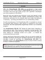
1. General
With this PowerSmoke 740 (HV) you purchased a high grade
accessory for your model airplane. PowerSmoke pumps are the most
innovative and most high grade pumps with significant advantages
over other systems on the market.
Best flow rate and optimal flow pressure at any time thanks to high
precision metal toothed wheels, highest manufacturing quality and
electronics optimized into the ultimate detail and totally manufactured
in Germany – providing untroubled fun for an extraordinary hobby!
As with its predecessor, the PowerSmoke 600, it is possible to connect
an electrical back pressure valve which is controlled by the pump
electronics. We offer appropriate magnetically valves in our accessory
program.
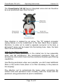
The PowerSmoke 740 HV ("HV" stands for Head Valve) integrates a
back pressure valve. This is unique in the fields of smoke pumps! This
back pressure valve makes the pump 100% leak proof and does not
allow leaking for unwanted smoke oil to pass – to benefit the
environment and your model!
Please read these instructions carefully. We do not assume liability for
damages caused by ignoring the operating instructions, as well as for
damages caused by operating the PowerSmoke 740 (HV). The
allowable usage of the PowerSmoke pumps is solely limited to smoke
oil flow in unmanned airplanes.
Hint:
PowerSmoke pumps are not applicable for Bio-Diesel! Be careful with smoke oils
including additives (aroma add-ons). Please read chapter 8!
Page 4 of 27
PowerSmoke 740 (HV)
Operating Instructions
Version 1.0
1.1. Differences to PowerSmoke 600 / XL
The new smoke pumps PowerSmoke 740 and PowerSmoke 740 HV
replace the older PowerSmoke 600 / PowerSmoke XL.
Electronics are completely redesigned and even smaller and more
space saving. Control of the pump motor is improved and the software
supplemented by reasonable features. The motor turns for the fraction
of a second full speed during power on to generate a better starting
torque.
A stronger motor is built into the new PowerSmoke pumps which
allows for more flow rate. It can be directly powered by 2S Lipo
batteries without problems. The PowerSmoke 740 HV can be powered
by 3S LiPo batteries because this pump has a wider suction hose
connector. The PowerSmoke 740 can only be supplied by up to 2S
LiPo batteries. At higher voltages this pump tends to cavitate.
The PowerSmoke 740 HV has a self purging passive check valve. The
cutoff valve and the self purging valve are integrated smartly into the
pump head. By using this valve it is assured, that the pump is
absolutely leak proof and that no smoke oil can pass when
disadvantageously mounted underneath the tank level. Furthermore,
exact on and off of the smoke is possible. Longer or permanent
smoking with a powered off pump is inhibited by usage of this passive
valve.
Of course, both pumps allow for usage of an electronically lock valve,
i.e. both pumps have a switching output, which controls an external
valve.
Hint:
During long pauses (> 1 day) the smoke oil tank should be drained completely.
Page 5 of 27
PowerSmoke 740 (HV)
Operating Instructions
PowerSmoke 740
PowerSmoke 740 HV
Picture shows PowerSmoke 740 HV with mounting brackets.
Page 6 of 27
Version 1.0
PowerSmoke 740 (HV)
Operating Instructions
Version 1.0
2. Specifications
2.1. PowerSmoke 740
Dimensions:
61mm x 27mm (Length x Diameter)
Quiescent Current: approx. 30mA (with powered receiver set)
Weight:
78g
Max. Flow Pressure: approx. 5.5 bar
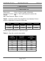
Table1 - maximum suction hose length for inner diameter 2.5mm /
4.0mm is dependent on amount of flow rate.
Hose ID
250ml/min
500ml/min
750ml/min
1000ml/min
∅ 2.5mm
600mm
300mm
---
---
∅ 4.0mm
1500mm
1000mm
750mm
600mm
Include length of pendulum in feed line length.
Table 2 – flow rate, current consumption
SupplyVoltage [V]
Flow Rate
[ml/min.]
Current
Consumption
[mA]
3.7
330
900
4.8
430
1100
6.0
550
1300
7.4
700
1400
9.6
900
1800
11.1
1100
2100
Page 7 of 27
PowerSmoke 740 (HV)
Operating Instructions
Version 1.0
2.2. PowerSmoke 740 HV (HeadValve)
Dimensions:
67mm x 27mm (Length x Diameter)
Quiescent Current: approx. 30mA (with powered receiver set)
Weight:
96g
Max. Flow Pressure: approx. 4.5 bar
Table1 - maximum suction hose length for inner diameter 4.0mm is
dependent on amount of flow rate. A suction hose with 2.5mm inner
diameter cannot be used with the PowerSmoke 740 HV due to their
bigger suction connector.
Hose ID
250ml/min
500ml/min
750ml/min
1000ml/min
∅ 4.0mm
1500mm
1000mm
750mm
600mm
Include length of pendulum in feed line length.
Table 2 – flow rate, current consumption
SupplyVoltage [V]
Flow Rate
[ml/min.]
Current
Consumption
[mA]
3.7
300
1000
4.8
400
1200
6.0
500
1400
7.4
650
1600
9.6
850
2000
11.1
1000
2300
Page 8 of 27
PowerSmoke 740 (HV)
Operating Instructions
Version 1.0
3. Mounting
It is advantageous to mount the pump higher than the tank. This is
especially true for the PowerSmoke 740 if not using the check valve.
When using a magnetically valve or the check valve, the mounting
position does not matter.
Page 9 of 27
PowerSmoke 740 (HV)
Operating Instructions
Version 1.0
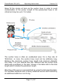
The PowerSmoke 740 HV has an integrated valve and can therefore
be even positioned lower than the tank.
Flow direction is marked by an arrow. The "R" marked connector
(swing fixture) is to be routed back to the tank. Back flow is approx.
35ml/min. In order not to install a separate connector to the tank, a
delivered T-piece can be looped into the tanking hose. Here, the back
flow is to be connected.
Hints for the filtering pendulum:
Flow rates of many pendulums in the market are to low (especially
sinter and felt pendulums). We recommend pendulums from our
accessories store which have low flow resistance besides good filtering
capabilities.
Use filtering pendulums when ever possible; you don't need additional
filters in the suction hose (there is no filter necessary in the pressure
line anyway).
Pay attention not to contaminate the hoses when connecting the
suction hose and pendulum hose. Possibly clean the hoses and the
pendulum using pressurized air prior to installation.
Page 10 of 27
PowerSmoke 740 (HV)
Operating Instructions
Version 1.0
Never fill the smoke oil tank via the suction hose in order to avoid
contamination of the pump. Length of the pressurized hose is not
critical and may be up to 1.5 meters.
The suction hose is often an unattended area. For a flow rate of
740ml/min. or more, the suction hose must not be arbitrarily long.
Retrieve the maximum suction hose length and minimum diameter
from table 1 for your desired flow rate. Observe that the suction hose
starts with a pendulum in the tank. Values in the table refer to the total
length which includes the pendulum length.
Mounting of the pump is accomplished by using the delivered brackets.
For aerobatic airplanes and or heavy vibrations secure each bracket by
an additional cable tie or an O-ring.
Page 11 of 27
PowerSmoke 740 (HV)
Operating Instructions
Version 1.0
Mount the clamps in a distance of 45mm at the desired position (e.g.
board inside of fuselage) with sheet metal screws 2.9x9.5 (delivered).
Additional cable ties or O-rings provide for additional support.
Remember, the pump remains always in the airplane and is exposed to
vibrations. The pump might be put into an appropriate foam insulation
hose (heating isolation material) which is glued into the fuselage or
fixed by cable ties. Damage caused by vibration is excluded from
warranty.
Hint:
Keep the pump clear from heavy vibrations because of its mass intensive parts
(pump). Damage by continuous vibrations can be encountered at electrical
connections or electronically parts.
4. Electrical Connection
All connectors are polarity proof using the Futaba coding. Of course,
JR connectors are appropriate, too.
The connector which is marked "RX" is provided a 3-pol patch cable
(control line) and then connected to the desired receiver output (or
output of a dual power supply, e.g. DPSI with servo current
distribution); a corresponding switch (servo channel) is to be selected
in the transmitter. No current flows practically to the receiver by this
patch cable.
The actual pump motor is separately supplied current by the connector
"BAT".
The connector "BAT" should be separated from the battery by a switch;
the quiescent current could discharge the battery otherwise.
Supply for the pump motor could be provided by a free receiver output
also. This saves an extra battery. Observe the current consumption of
the pump motor because the current loads the printed circuit board
tracks of the receiver.
Page 12 of 27
PowerSmoke 740 (HV)
Operating Instructions
Version 1.0
In order to unburden the receiver, the supply can also be applied by a
free channel of a battery switch with servo current distribution (e.g.
DPSI Mini, DPSI RV or DPSI 2001 RV). Here too, observe the
maximum possible current, especially, when the selected output
voltage of the dual power supply is lower than the voltage of the
connected battery.
It is saver to supply the pump with a separate battery. The supply of
the pump motor should contain a switch because even when the pump
is inactive, a small quiescent current (180µA) discharges the battery
slowly. Alternatively, the battery can be simply disconnected.
Hint:
Do not use batteries for ignition systems or turbines as supply. Hereby, immense
disturbances of the receiver set are possible. Be aware, that up to 6 amps of
power on current can occur.
Page 13 of 27
PowerSmoke 740 (HV)
Operating Instructions
Version 1.0
5. Connecting to Tanking System
The smoke oil pump is protected by locking nipples against
contamination. They are not needed anymore. Flow direction is
indicated by an engraved arrow.
Hint:
Flow direction is not reversible by electronics!
On the suction hose side of the PowerSmoke 740 a hose with an inner
diameter of 2.5mm can be used. We recommend for all pumps a
suction hose with 3.5mm or 4mm inner diameter (simply connectable
by adaptor instead – see photo). Retrieve maximum suction hose
length as well as pendulum type from table 1. The PowerSmoke 740
HV has a bigger suction connector where a 2.5mm suction hose
cannot be adapted (only the bigger hoses with 4mm e.g.).
Page 14 of 27
PowerSmoke 740 (HV)
Operating Instructions
Version 1.0
Our connection set includes all parts in order to allow for optimal flow
rates.
On the pressure side we recommend 2.5mm plastic hoses (PUN) or
Tygon hoses, at least near the exhaust system. We recommend
changing from the plastic or Tygon hose to a heat resistant Viton hose
(close to the muffler) at late as possible (see chapter 6).
Dependant on pressure hose length, injection form, flow rate and
counter pressure a pressure of up to 4 bar can arise in the flow hose.
The pressure hose must support this pressure. In order to connect the
plastic hoses it is advantageous to put some oil onto the connectors or
heating up the hoses carefully. After the hoses are connected, they will
not fall lose themselves anymore. If it is necessary to remove hoses,
they must be cut lose by a side cutter, the same technique is to be
used for removing remaining pieces. Do not use a knife, the
connectors get "scratched" and are possibly not 100% leak proof
anymore. Make sure, no plastic parts enter the pump.
6. Connecting to Exhaust System
A heat resistant hose (available in our shop) is to be put onto the metal
nipple of the muffler or manifold. Please do not use a plastic or
Tygon hose! For turbines, the last piece must be of metal material
(stainless steel-, Titan- or brass pipes, but no aluminum pipe). We
recommend switching to plastic or Tygon hoses in appropriate distance
to all heat sources.
If a pipe of 3mm outer diameter is used, the hose can be directly put on
(secure with a small bracket or wire). You find fitting hose adapters for
4mm outer diameters in our shop. Also adapters for 3mm Tygon hoses
are available as accessories.
Page 15 of 27
PowerSmoke 740 (HV)
Operating Instructions
Version 1.0
Please be aware that soldered pipes, especially with model airplanes
powered by piston engines, do not allow for long distances (max.
60mm) because vibration breakages are preprogrammed.
An additional support is in order for longer pipes which must be
mounted to the same part as the pipe itself; this means, do not mount
the support to the fuselage if the pipe is soldered to the manifold.
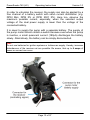
Contents of delivery PowerSmoke 740 HV
Page 16 of 27
PowerSmoke 740 (HV)
Operating Instructions
Version 1.0
7. Initial Operation / Teach-in of Pump
Hint:
After mounting and finishing connections it is advisable to test and possibly
program (teach in) the smoke oil pump.
Generally, after mounting any electrical add-on device, a range test with powered
pump should be conducted. Don't let the pump run dry during these adjustments
or a range checks!
For the first tests or range checks it is best to reroute the pressure pipe
back to the smoke oil tank (e.g. by putting the pressure hose of the
smoke oil pump back onto the fuel nozzle in order to pump the oil in a
circle). First fill the smoke oil tank (approx. half full). In order to achieve
optimal regulation no travel limit should be programmed at the
transmitter. It is possible to only use one half of the servo travel range
to use the other "half" for a different function. Corresponding to the
travel range adjustments of your transmitter the PowerSmoke740 (HV)
can be programmed (taught in).
For programming of the PowerSmoke740 (HV) a programming
jumper, a functioning radio control (or servo tester) as well as sufficient
power supply are necessary.
Hint:
As long as the PowerSmoke (HV) is in programming mode the pump motor is not
driven, i.e. the device can not accidentally pump and therefore is in a safe mode.
Page 17 of 27
PowerSmoke 740 (HV)
Operating Instructions
Version 1.0
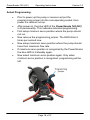
Actual Programming:
•
•
•
•
•
•
•
Prior to power up the pump or receiver set put the
programming jumper into the corresponding socket, then
power the receiver set up.
After power on, the blue LED of the PowerSmoke 740 (HV)
is lit permanently. This indicates activated programming.
First setup minimum servo position where the pump should
not run.
Now remove the programming jumper. The LED blinks 5
times per second now.
Now setup maximum servo position where the pump should
have their maximum flow rate.
If maximum servo position is recognized by the PowerSmoke
the blue LED is lit steadily again.
Now select minimum servo position again. Only when
minimum servo position is recognized, programming will be
left.
Page 18 of 27
PowerSmoke 740 (HV)
Operating Instructions
Version 1.0
Hint:
If the programming jumper is recognized being plugged in after finishing
programming the blue LED flashes 10 times per second until the programming
jumper is removed.
Hint:
If after removal of the programming jumper no valid servo signals are received,
programming is interrupted immediately without changing the configuration.
Hint:
Servo travel range between the off-position and the maximum flow rate must be
at least 30%.
The following servo travel ranges are allowed:
-100% to +100% (=200%)
-10% to +30% (= 40%)
Invalid range:
0% to +20% (= 20%)
Preprogrammed values at delivery:
1.1ms (-100%) start position (no flow rate – pump off)
1.9ms (+100%) end position (maximum flow rate)
Hint:
For safety reasons the pump turns on only above 10% of the start position and
then runs with a minimum flow rate of 20%.
An optimum flow rate is best assessed in flight based on the generated
amount of smoke. Adjustment is done e.g. via "servo travel" of the
transmitter. Experts could also program the flow rate depending on the
throttle position. The pump allows that thanks to it's electronically
regulation features.
Page 19 of 27
PowerSmoke 740 (HV)
Operating Instructions
Version 1.0
The flow rate is correctly adjusted if there are no oily remains on the
fuselage; the flow rate is to reduce when a lot of remains are
encountered.
Hint:
After powering the receiver set on the actuator on the transmitter must be set to
“pump stop position” first. Only then the pump can be arbitrarily turned on or off.
This inhibits an erroneous running of the pump and e.g. uncontrolled filling of the
muffler when turning the system on.
8. Hints for Daily Operation
The smoke oil pump is free of maintenance and very long lasting. The
heart of the smoke oil pump is a high grade toothed wheel pump. As a
matter of principals this type of pumps is not applicable for running dry.
Periods of running dry must be kept as short as possible.
Hint:
Especially when new 60 seconds of running dry could be already too long for the
PowerSmoke 740 (HV) and damage the pump!
Do not fully empty the smoke oil tank during flight. It is advantageous
to start a stop-watch when starting the pump (and stopping the watch
when stopping the pump); this indicates on-time when to stop the
pump. If for any reason hectic comes up powering the pump off could
be easily forgotten. In order to avoid unwanted powering on of the
pump a "main switch" should be looped into the power supply (e.g.
EMCOTEC MPS).
If you do not want to use a switch disconnect the pump from the
battery.
We point out that especially damages caused by running dry are not
covered by warranty.
Page 20 of 27
PowerSmoke 740 (HV)
Operating Instructions
Version 1.0
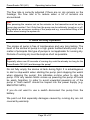
The adjustment of the pump in respect to the transmitter signal can
change over time. This is especially caused by the "running in" of the
pump and the motor.
The result could be that the flow rate changes over time (in general
somewhat increasing) when the pump is not running full speed. You
can correct this by changing the "travel range" easily. Alternatively the
pump can be newly taught in.
If not used for a longer time (especially in winter time) and when
smoke oils with additives are in use corrosion can occur. In general
these are smoke oils with odorous substances (e.g. smoke oils with
strawberry or banana aroma). These additives are often acidic and
heavily hygroscopic and therefore attack the toothed wheels of the
pump. Such smoke oils also deposit Emulsions (water oil
combinations). These are recognizable as brown spots in the canister.
If you do not want to resign from using such oils you must conserve the
pump before pausing a longer time. Fill the smoke tank with acid-free
oil (e.g. sewing machine oil or low viscosity machine oil) and then run
the pump until consistently flooded by oil.
Hint:
Generally its senseful to flood the pump with acid-free oil during long pauses
(e.g. winter). This also will extend the life time of the pump.
Hint:
We point out that damage caused by corrosion is not covered by warranty!
Page 21 of 27
PowerSmoke 740 (HV)
Operating Instructions
Version 1.0
9. Using a Back Pressure Valve
By principal there are no pumps which lock in normal flow direction;
even not when some provider promise or pretend. This means that a
pump only can increase a volume but never totally lock it. Even the
best pumps tend to pass more or less smoke oil without additional
locking means when powered off.
Through expansion of the tank volume by e.g. heat smoke oil can
reach and flood the muffler. This can be avoided by back pressure
valves which are spring loaded and therefore need some minimum
pressure in order to open at all. Unfortunately even toothed wheel
pumps of good quality generate only low pressure when running dry.
This means a spring loaded back pressure valve of a pump makes
intake more difficult or even inhibits it. It is possible that a new pump
can open such a valve but does not manage it after some hours of
operation anymore.
Therefore we recommend usage of the PowerSmoke 740 HV with
integrated back pressure valve or an additional check valve in the
pressure line of the PowerSmoke 740.
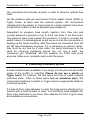
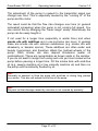
9.1. PowerSmoke Check-Valve
Our in house developed valve is a cost saving alternative to a
magnetically valve. It can be looped in between the pump and the
muffler without problems. A vent pipe (return pipe) to the tank is
necessary. By using this valve you make sure that the pump does not
pass smoke oil unintentionally. Exact turning on and off is assured.
Longer or permanent smoking when the pump is turned off is inhibited
by this passive valve. Flow rate is only reduced by 5% when using this
valve.
Page 22 of 27
PowerSmoke 740 (HV)
Operating Instructions
Examples based on PowerSmoke 600
Page 23 of 27
Version 1.0
PowerSmoke 740 (HV)
Operating Instructions
Version 1.0
9.2. Magnetically Valve
A very comfortable possibility is to loop in a magnetically valve into the
pressure line. The pump electronics of the PowerSmoke 740 (HV)
allows for such a valve to be connected and controlled. Theoretically
any magnetically valve with 5 volts and a maximum of 300mA current
can be connected. Such a magnetically valve must have a sufficient
wide diameter though; otherwise the pump motor or electronics might
be over loaded. Fitting valves are available as accessories in our shop.
Valves with 3-wire connection cables usually are only wired with brown
(minus) and red (plus). Under no circumstances use valves which
possess their own electronics.
Page 24 of 27
PowerSmoke 740 (HV)
Operating Instructions
Version 1.0
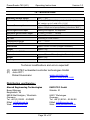
10. Technical Data
Operating Voltage Range
4.8V .... 12V
Current Connector Pump
4 cells NiCd/NiMH (4.8V) up to 2 cells LiPo (8.4V)
HV version: up to 3 cells LiPo (11.1V)
Current Consumption
approx. 30mA electronics, up to 2.3A pump
approx. 180µA out of pump battery (connector "BAT“)
Servo Signal Level Input
starting from approx. 2V amplitude
Allowable Servo Pulse Length
+/-100% (1.10ms .... 1.90ms)
Maximum Pressure
approx. 5bar
CE-Test
according to 2004/108/EC
Temperature Range
-0°C .... +70°C
PowerSmoke 740
Dimensions
approx. 61mm x 27mm (Length x Diameter)
Weight
approx. 78g
PowerSmoke 740 HV
Dimensions
approx. 67mm x 27mm (Length x Diameter)
Weight
approx. 96g
Warranty
24 month
Technical modifications and errors expected!
(C) EMCOTEC embedded controller technologies GmbH
(P) June 2011
Robert Hussmann
www.emcotec.de
www.rc-electronic.com
Distribution und Service:
Atecad Engineering Technologies
Bernd Albinger
Berglandstr. 38
88348 Bad Saulgau / Moosheim
Germany
Tel. +49 (0) 05242 - 4049633
EMail: [email protected]
Web: www.atecad.de
EMCOTEC GmbH
Waldstr. 21
86517 Wehringen
Germany
Tel. +49 (0) 8234 – 95 98 90
EMail: [email protected]
Web: www.powersmoke.de
Page 25 of 27
PowerSmoke 740 (HV)
Operating Instructions
Version 1.0
11. Warranty
EMCOTEC GmbH shall issue a 24-month warranty on the PowerSmoke 740
(HV). The guarantee period shall begin with delivery of the equipment by the
retailer and shall be not extended by any guarantee repair or guarantee
replacement.
During the period of guarantee, the warranty shall cover the repair or
replacement of any proven manufacturing or material defects at no charge. There
shall be no specific entitlement to repair work. In case of a guarantee claim, the
manufacturer shall reserve the right to exchange the equipment for a product of
equal value if repair of the item is not feasible for economic reasons. There shall
be no assumption of liability for consequential damages that are brought about by
a proven defect during operation of the PowerSmoke 740 (HV). There shall be
no extended claims for damages.
All transportation, packaging and travel expenses shall be borne by the
purchaser.
No liability shall be assumed for any damages during transport.
If repair is needed, the equipment must be sent to the appropriate service
center of the respective country or directly to EMCOTEC GmbH.
The guarantee shall only be valid when the following conditions are met:
The guarantee document (original invoice) must include the delivery date,
the company stamp, the serial number and signature of the retailer.
No intervention in the equipment may have been undertaken.
It must have been operated in accordance with our operating instructions.
Only the power sources and other accessory devices and components that
were recommended by us may have been used.
The guarantee document, the original invoice and other pertinent
information regarding the malfunction (a short description of the defect)
must be included with the transmittal.
The equipment must still be the property of the initial purchaser.
If equipment is sent in that later proves to be functional following an initial
inspection, we shall impose a flat processing fee of € 20.
In all other respects, the general business terms and conditions of
EMCOTEC embedded controller technologies GmbH shall apply for any
items not listed.
Page 26 of 27
PowerSmoke 740 (HV)
Operating Instructions
Version 1.0
Legal information:
Trademarks:
The following names are registered trademarks:
EMCOTEC
DPSI - Dual Power Servo Interface
DPSI RV
Other product names mentioned in this manual may also be trademarks or registered
trademarks of their respective owners.
Copyright information:
This manual is copyrighted by EMCOTEC GmbH. All rights reserved. This document may not
be copied either entirely or in part, nor may it be transferred to any type of medium or
translated into any other language without the express written approval of EMCOTEC GmbH.
Manual Note:
EMCOTEC GmbH reserves the right make changes to this manual and to equipment
described herein without notice. Considerable effort has been made to ensure that this manual
is free of errors and omissions. We shall not assume responsibility or liability for any errors that
may be contained in this manual nor for any incidental, concrete or consequential damage that
may arise from the provision of this manual, or the use of this manual in operating the
equipment, or in connection with the performance of the equipment when so operated.
Page 27 of 27