1
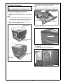
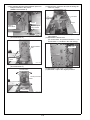
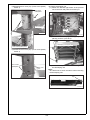
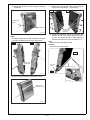
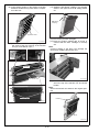
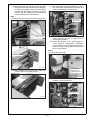
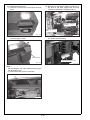
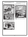
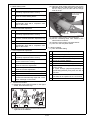
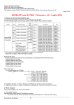
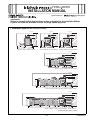
7000/ 6000 INSTALLATION MANUAL Applied Machine: 7000/ 6000 <Important> Be sure to correctly follow the procedures in order as explained in this Installation Manual. If you do not follow the procedure in order, the image trouble may occur. I. Installation space (Machine combination examples) (unit: mm) (unit: mm) (unit: 1639 1639 1478 1639 1478 1183 1041 1041 993 1478 1076 1041 1046 315 100 766 950 mm) 315 100 100 1561 1046 100 1561 200 2143 SD-506 + RU-509 + Machine + PF-602 OT-502 + Machine + DF-622 + MB-504 OT-502 + Machine + OC-506 + MB-504 (unit: mm) 1639 1750 1478 1183 1041 990 100 116 424 250.5 410 760 946 100 3106.5 FS-612 + RU-509 + Machine + DF-622 + PF-602 (unit: mm) 1639 1478 1183 1020 1041 477 100 254 117 544 1170 410 400 760 718 100 4573 FS-521 + SD-506 + FD-503 + RU-509 + Machine + DF-622 + LU-202 (unit: mm) 1639 1478 1183 1041 1223 1020 1360 1170 785 100 410 760 5631 946 100 PB-503 + SD-506 + LS-505 + RU-509 + Machine + DF-622 + PF-602 Machine weight: Approx. 353kg E-1 A1DU960111 II. Pre-installation Check Items No. 1. Select a level and stable place for installing the machine. 2. Be sure to use a power source of the voltage and frequency indicated in the product specifications. Ensure that the current carrying capacity of the power outlet is at least equal to the current listed in the product specifications. 3. Power the machine directly from a dedicated power outlet. (Do not use an extension cord.) 4. Do not plug or unplug the power cord with wet or dirty hands, otherwise you may get an electric shock. 5. Avoid a hot and humid environment, or a place exposed to direct sunlight. 6. Avoid a dusty location, or a place near volatile and flammable substances. 7. Avoid a poorly ventilated place. Name Shape Shape Q’ty 9. Sub power switch label 1 A03UIXC014SA 10. Developing unit label 6 A1RFIXC008CA 11. Arm cover (Fr/Rr) 1 A1DUIXC003CA 12. Installation manual 1 13. User’s guide (Except for Europe) III. Accessory parts No. Name Q’ty 1. Exhaust cover each 1 14. Power cord (For option) 1 1 15KVIXC014SA 15. Clamp A03UIXC005SA 2. Developer (Y/M/C/K) each 1 A1DUIXC001CA 3. Developing unit (Y/M/C/K) A03UIXC007SA each 1 4. Transfer unit 1 A03UIXC008SA 5. Belt cleaner unit 2 16. TP screw M4x6 8 17. TP screw M3x4 13 18. TP screw M3x6 7 19. SEMS II screw M4x8 2 20. Bind screw M4x10 2 21. Truss screw (black) M4x6 5 22. Service port board 1 1 A03UIXC009SA 6. Separation claw unit A1DUIXC004CA 1 23. Board installation plate A03UIXC010SA 7. Operation panel 1 A1DUIXC005CA 1 24. Band (for IC-601) A03UIXC012SA 1 A1DUIXC006CA 8. User’s guide holder 25. CD-ROM 1 1set A03UIXC013SA E-2 5. Remove the locking tapes from inside each of the trays. Remove the lock guide tape last. Note: When removing locking tapes from inside each of the trays, be careful not to damage the black PET. IV.Installation Procedure Note: Release all locks, and do not plug the power cord into the outlet until you are instructed to do so. Black PET 1. Remove the wrapping sheet on the top. 2. Inspect the outward of the Machine. 3. Remove the locking tapes put on the exterior panels. Note: • Locking guide tapes indicate the portions to be unlocked; those tapes should be removed after the completion of each unlocking procedure. Locking tape Locking tapes 4. Open the toner supply unit external door and remove the locking guide tapes Locking guide tape A03UIXJ001CB 6. Remove the optics unit locking screw on the left side of the Machine. Wrapping sheet Locking tape Locking screw Locking guide tapes Protector paper A03UIXJ003SB 7. Open the toner supply unit and the front door of the Machine. (1) Open the front door of the Machine. Front door Locking guide tapes Toner supply unit external door A1DUIXC007CA A1DUIXC008CA E-3 8. Release the ADU lock. (1) Remove the two screws of the ADU lock bracket (bottom left). (2) Loosen the upper lock screw of the toner supply unit. Upper lock screw of the toner supply unit ADU lock bracket (Bottom left) A1DUIXC009CA (3) Loosen the lower lock screw toner supply unit, open the toner supply unit. A1DUIXC011CA (2) Remove one ADU lock bracket screw (top). ADU Lock bracket(top) Toner supply unit lock screw (under) A1DUIXC010CA A03UIXE061SA (3) Pull out the tray/1 and remove 2 ADU locking tapes. Note: The tapes on the lower left are overlapped and the inner tape cannot be removed. (4) Remove the mirror mat. (5) Loosen the one screw of the fan cover to open it. Locking tapes Fan cover screw Mirror mat A1DUIXC052CA A1DUIXC012CA E-4 (4) Remove 2 ADU lock bracket screws (lower right), and then remove the ADU lock bracket. Note: Do not remove the red tags in this step because it shows that locking materials are on ADU inner part side. ADU Lock bracket (bottom right) Tags for lock marker Locking tape A1DUIXC013CA (5) Remove the tape from the ADU section, remove 1 screw, and then remove the locking material. A03UIXE002CA (7) Pull out the ADU unit. (8) Remove the locking tape from Lever M6, and remove the ADU locking bracket (upper). (2 screws) tape Locking tape ADU Lock bracket(top) Locking material A1DUIXC014CA A03UIXE010SB (9) Remove the desiccating agent. (10)Remove the locking tapes and the protection paper. (6) Turn the ADU release lever to the left, while keeping the ADU lock open. Protection paper Desiccating agent Locking tape ADU lock A1DUIXC016CA ADU release lever A1DUIXC015CA E-5 (11) Remove the locking tape and two locking materials(point of a thread of a red tag) from ADU unit inner part side. (2) Remove 4 screws, and then remove the top cover (Rr). Locking tape Top cover (Rr) A1DUIXC020CA Locking materials (3) Remove 2 screws, and then remove the top cover (Rt). A03UIXE003CA (12) Remove the locking tapes from the right-hand side of the ADU unit. Remove the spacer. Locking tapes Top cover (Rt) Spacer A1DUIXC019CA (4) Remove the rear cover. (12 screws) A1DUIXC017CA (13) Re-insert the ADU unit into the machine and lock the ADU release lever. 9. Install the operation panel. (1) Remove 4 caps. Caps Rear cover A1DUIXC021CA A1DUIXC018CA E-6 (7) Mount the operation panel. (TP screw M4x6: 6) (5) Remove the board cover. (9 screws) Board cover TP screws M4x6 TP screws M4x6 TP screws M4x6 A1DUIXC022CA A1DUIXC024CA (6) Mount the operation panel on the main body. Set 2 base pins on the operation panel to the holes on the main body and turn it to the arrowmarked direction to lock. Note: To mount the operation panel, be sure to pass the connectors of the operation panel through the operation panel installation section and pull them out at the rear of the machine. (8) Set 2 wiring harness of the operation panel in 7 clamps. Note: Be careful not to set the wiring harness of the operation panel crossed over the wiring harness A. Clamp A Operation panel installation section Operation panel wiring harness Operation panel wiring harness Clamps Clamps A1DUIXC025CA (9) Connect 2 connectors. Mount of operation panel A1DUIXC023CA Connectors A1DUIXC026CA E-7 (10)Fix 2 wiring harness of the operation panel in 2 clamps as shown in the picture. (SEMS II screw M4x8: 2) (13)Connect the connector and set the wiring harness in 2 clamps. Connector Clamps Clamps SEMS II screws M4x8 Operation panel wiring harness A1DUIXC030CA A1DUIXC027CA (14)Reinstall the top covers (Rt and Rr) to the original positions. (15)Reinstall the board cover. (TP screw M3x4: 22 (removed screws: 9 + TP screw M3x4:13: bundled in the main body)) (11)Install the board installation plate. (TP screw M4x6: 2) Board installation plate Board cover TP screws M4x6 A1DUIXC028CA (12)Mount the service port board. (TP screw M3x6: 4) A1DUIXC049CA (16)Reinstall the rear cover. (12 screws) (17)Reinstall 4 caps to the original positions. TP screws M3x6 Service port board TP screws M3x6 A1DUIXC029CA E-8 (18)Install the arm cover (Fr). (Truss screw (black) M4x6: 3) 10.Set the developing unit. (1) Return the left and right levers of the process unit to the front and pull them toward you. Truss screw (black)M4x6 Arm cover (Fr) Levers A1DUIXC031CA A1DUIXC033CA (2) Remove the developing unit support part (2 places) (screws: 3 pcs each). Developing unit support parts Truss screws (black) M4x6 (19)Install the arm cover (Rr). (Truss screw (black) M4x6: 2) A03UIXE024SA Truss screws (black)M4x6 (3) Remove the tape from the toner loading slot of the developing unit. Note: Be careful not to touch the sleeve when removing the developing unit. Arm cover (Rr) Tape A1DUIXC032CA A03UIXE025SA E-9 (4) Install the developing units in the order YMCK (from the top) in the machine. To install, insert each developing unit on the left side first and then set the right side. Note: When slipping the unit on the rail, move straight. (Avoid slanting to the right or left) (5) Install the developing unit support part (2 places) (screws: 3 pcs. each). To install, insert the bottom of the developing unit support part and tighten with the screws. Note: Make sure that the springs do not come off. Developing unit support parts Developing unit Straight Y M A03UIXE027SA C (6) Connect the connectors on the process unit to the YMCK developing units. K A03UIXE026SA Connector Connector location of connections A1DUIXC034CA E-10 11.Remove the drum blade pressure release screw for each color. Note: • Do not expose the drum to light for a long time. • Do not touch drum surface. • Do not damage drum surface. • Return the drum to the position it was in before it was removed. • When installing the drum for K (at the very bottom shelf) take care not to get the Mylar sheet entangled. (1) Remove the drum from the process unit. (3) Apply setting powder on both side of the drum, and rotate both side edges with fingers in the direction shown in the figure to brush setting powder off. Note: Be sure to rotate both side edges with fingers not to touch image area. Do not rotate in the opposite direction. Application area Process unit Drum A03UIXE029SA (2) Remove the drum blade pressure release screws (front/rear: 1 red screw each).(YMCK processing) Front Edge Drum blade pressure release screw A03UIXE007CA Rear Drum blade pressure release screw A03UIXE030SA E-11 (4) Install the drum in the original position. Note: Once the drum for K (at the very bottom shelf) has been installed, ensure that the mylar sheet is not entangled. 12. Install the transfer unit. (1) Loosen the two screws of the transfer unit fixing materials (top/bottom). There are two screws in the top piece, and two screws in the lower piece. Turn the transfer unit fixing materials counterclockwise to remove. Transfer unit fixing materials A03UIXE031SA (2) Remove the transfer unit stand on the rear side of the toner supply unit. Transfer unit stand A1DUIXC035CA (3) Remove the transfer unit from the box. Note: When removing the transfer unit from the box, never hold it at the positions shown in the figure. When taking it out of the bag, be careful not to touch the belt. A03UIXC001SA Mylar A03UIXE041SA (5) Return the process unit to the machine. (It is not necessary to lock it) A03UIXC002SA E-12 (7) Remove the 1st transfer roller locking material (front and rear 6 places: 1 screw each). (4) Stand the transfer unit up using the transfer unit stand. Front Rear Transfer unit stand Transfer unit stand 1st transfer roller locking materials A03UIXE036SB A1DUIXC036CA (5) Remove the two lock screws. (Red screws) Note: The left and right lock screws are different lengths, note when reattaching them if you move them. Front Rear (8) Install the separation claw unit. Place the claw unit into the slit in the bottom right of the transfer unit, and screw the unit in while aligning it with the left projection. (TP screw M3x6: 1 pc.) Note: Be careful not to damage the belt. Caution: Be careful not to get injured. Front Lock screws (Red screws) TP screw M3x6 Separation claw unit Slit Rear A03UIXE034SC (6) Remove the transfer unit protection cover. A03UIXE006CA Transfer unit protection cover A03UIXE035SB E-13 (9) Apply setting powder on the surface of the belt between the belt driving roller and the separation claw unit. (11) Rotate the belt driving coupling in the direction shown in the figure to brush all setting powder off. Belt driving coupling Application area A1DUIXC037CA A03UIXE038SA (10) Install the belt cleaner unit by aligning it with the angle of the top grooves of the transfer unit (TP screw M3x6: 2 pcs.). (12) Pull out the process unit again. (13) Press the portion marked with an arrow to confirm that the drum cartridge is correctly set. Note: Incorrect setting of the drum can damage the drum when installing the transfer unit. Grooves Belt cleaner unit A03UIXC003SA (14) Remove the transfer unit stand, pull the handle on the top of the transfer unit, and lift the handle. Note: Return the transfer unit stand to the original position. TP screws M3x6 Handle A03UIXE039SA Pins A03UIXE042SA E-14 (15) Set the transfer unit with the surface of its belt facing the drum side. Position the unit obliquely, as shown in the figure, and move it into place from the rear, then align it so that the pins of the transfer unit are engaged by the positioning hooks (4 places) in the front and rear. Note: Be careful not to hit the drum with the transfer unit. (17) Turn the transfer unit fixing material in the direction of the arrow until it reaches the screws, and secure it with screws (2 screws each). Transfer unit fixing materials Rear side A03UIXE045SA (18) Push the process unit all the way (until it clicks), and bring the left and right levers to their original positions. (19) Check the position of the white plastic for cross direction magnification adjustment (Y,M,C). When it is not positioned as shown in the picture, pull out the process unit to move it to its normal position Note: Never loosen the screw. Positioning hooks Front side Positioning hooks A03UIXE043SA (16) After installing the transfer unit, return the handle back to the original position. Cross direction magnification adjustment plastic A1DUIXC051CA Handle (20) Install a Bind screw M4x10 at each of the two locations on the transfer unit. Bind screws M410 A03UIXE044SA A03UIXE046SA E-15 13. Install the exhaust cover. (1) Remove 2 screws on the rear side of the main body. (2) Remove the developer charging plate set on the back of the toner supply unit, and then remove the developer charging funnel / L. Developer charging funnel / L Developer charging plate A1DUIXC038CA A1DUIXC041CA (2) Slide and install the exhaust cover, and then secure it with 2 screws. (3) Place a piece of paper below the toner insertion slots to prevent soiling. Exhaust cover Paper for prevention of dirt A1DUIXC039CA A03UIXE049SA 14. Set the developer. Note: Set developers in the order YMCK (from the top of the developing unit). (1) Remove the top cover/Fr.(2 screws) Top cover /Fr A1DUIXC040CA E-16 (4) Align the holes of the developer charging plate to the developer charging plate fixing screws, and slide it to the right to secure it. Note: Be careful not to nip the wiring harness. (6) Take out the developer charge funnel /U which is bundled in the developer. Unfold the developer charge funnel /U and set it to the developer charge funnel /L. Note: When opening the developer charging funnel/U, bend it outward against the inclination to flatten it. Developer Charging funnel/U (Y) developer charging plate fixing screws (M) (C) (K) developer charging plate fixing screws Developer Charging funnel/U A1DUIXC044CA Developer charging plate A1DUIXC042CA (5) Set the developer charging funnel / L to the toner loading slot of the developing unit. Place it on top of the developer charging plate as shown in the figure. Developer charging plate (7) Plug the power cord into the outlet. Caution: Be sure to plug the power plug completely into the outlet. Developer Charging funnel/L A1DUIXC043CA E-17 (8) Set the developer. Step 1. Turn ON the Main power switch. 2. Enter Service Mode. Note: •Refer to procedures in the Service Manual to enter into the Service Mode. •To enter into the Service Mode, follow the stepsfrom the sub power OFF status described in the Service Manual. Note: When removing the developer charging plate from the machine, lift the right side of the stopper plate, and slide the developer charging plate to the left side to remove it. 3. [Service Mode Menu screen] Touch the “Process Adjustment”. 4. [Process Adjustment Menu screen] Touch the “Drum Peculiarity Adj.” Stopper plate 5. [Drum Peculiarity Adjustment Menu screen] Touch the “Auto. Developer Charge”. A03UIXE053SA 6. Check if the screen shows [Y] If the yellow developer is ready, touch the [Start]. 15. Return the developer charging funnel / L and the developer charging plate to the original position. 16. Reinstall the top cover/Fr. (2 screws) 17. Tighten the screw on the fan cover. (1 screws) 18. Close the toner supply unit, and tighten the toner supply unit lock screws. (2 screws) Note: To fasten the two lock screws of the toner supply unit, position the unit by fastening the screw at the lower section first, before fastening the one at the upper section. 19. Close the front door of the machine. 7. Pour in the developer. A03UIXC004SA 8. After the developer is completely poured in, touch the “Cancel”. V.Adjustments and Settings 9. Touch the “M” (magenta). 10. Pour in the developer in the same manner as for yellow. Note: • Ensure before loading that the color of the developer matches to the color displayed on the screen. • Make sure the developer charging funnel / L is cleaned before moving from one color of the developer to the next. • Replace the developer charging funnel /U for each color of developer. • Follow the same procedure for cyan (C) and black (K) developers. Note: Execute the adjustments and settings below. 1. Toner density sensor initial auto adjustment Step 1. Return to Service Mode. 2. [Service Mode Menu screen] Touch the “Process Adjustment”. 3. [Process Adjustment Menu screen] Touch the “Drum Peculiarity Adj.” 4. [Drum Peculiarity Adjustment Menu screen] Touch the “Toner Density Sensor Init.” 5. [Toner Density Sensor Initial Auto. Adj. screen] Select the “All” and touch the “Start”. 6. This process takes about 3 minutes and 40 seconds and automatically stops with a completion message on the screen. E-18 2. Blade setting mode (3) Open the toner supply unit interior door for the appropriate color, and push the toner bottle to be set, making sure the side with the triangle mark is on top. Step 1. Touch the “Return” to return to the [Drum Peculiarity Adjustment Menu screen]. Toner supply unit external door 2. [Drum Peculiarity Adjustment Menu screen] Touch the “Blade Setting Mode”. 3. Touch the “Int. Trans. Belt”. 4. This process takes about 20 seconds and automatically stops with a completion message on the screen 3. Gamma automatic adjustment Step 1. Touch the “Return” key to return to the [Drum Peculiarity Adjustment Menu screen]. Triangle mark A1DUIXC045CA (4) Close the toner supply unit internal door. (5) Set the remaining three color bottles in the same manner as above. (6) Close the toner supply unit external door. (7) Turn OFF the sub power switch. 2. [Drum Peculiarity Adjustment Menu screen] Touch the “Gamma Automatic Adjustment” key. 3. Check the “0” and touch the “Start”. 4. This process takes about 2 minutes and automatically stops with a completion message on the screen. 6. Various settings (1) Time and Date setting 4. Color Regist auto adjustment Step Step 1. Turn ON the Sub power switch. 1. Touch the “Return” key to return to the [Drum Peculiarity Adjustment Menu screen]. 2. Press the [Utility/Counter] key. 2. Touch the “Close” key twice to return to the [Service mode menu screen]. 3. Touch the “Administrator Setting”. 3. [Service Mode Menu screen] Touch the “Machine Adjustment”. 5. Touch the “Date / Time Setting”. 4. Touch the “System Setting”. 6. Set date and time using the numeric keypad on the screen. It cycles through [day/month/year/time] or [month/day/year/time] every time the “Set” is touched. 4. [Machine Adjustment Menu screen] Touch the “Printer Adjustment”. 5. Touch the “Color Registration Auto. Adj.” 6. Touch the “Start”. 7. Be sure to touch the “OK”. The date will be updated to the current date. 7. This process takes about 1 minutes and 30 seconds and automatically stops with a completion message on the screen. 8. Touch “Exit”. 5. Set the toner bottles. (1) Shake the toner bottle as shown in the figure below, and remove the cap. A03UIXC015SA (2) Open the toner supply unit external door on the right side of the machine. E-19 7. Insert and install the OC-506 (optional) to the hinge hole on the top of the Machine. (2) Setup Date Input Step 1. Enter Service Mode. Note: •Refer to procedures in the Service Manual to enter into the Service Mode. OC-506 2. [Service Mode Menu screen] Select “System Setting”. 3. [System Setting Menu screen] Select “Setup Date Setting”. 4. [Setting Date Setting Menu screen] Input the proper date using the numeric keypad on the screen. It cycles through [day/month/year] or [month/ day/year] every time the “Set” is touched. A03UIXE056SA 8. Install the OT-502(optional) on the left side of the machine. Note: When installing the optional paper exit tray, see the OT-502 installation procedure. 9. Install the User’s guide holder on the left side of the machine. Note: The User’s guide holder can also be installed on the optional. 5. Be sure to touch the “OK”. The date will be updated to the current date. 6. Leave the machine in [Service Mode Menu] (do not turn the power OFF). (3) Telephone number setting Step 1. [System Setting Menu screen] Select “Service Center TEL/FAX”. 2. [Service Center TEL/FAX Setting Menu screen] Select “Service Center TEL(16)”. 3. Input numbers using the numeric keypad on the screen.(16 digits) 4. Select “Service Center FAX(16)”. 5. Input numbers using the numeric keypad on the screen.(16 digits) 6. Be sure to touch the “OK”. OT-502 Paper exit tray unit (option) 7. Leave the machine in [Service Mode Menu] (do not turn the power OFF). User's guide holder (4) Enter ADF serial number.(If ADF is installed.) You can find the 13-digit serialnumber on the bottom when you open the ADF. Note: When installing the optional DF-622, see the DF622 installation procedure. A03UIXE057SA 10. Put the sub power source label aligning it to the groove. Step 1. [System Setting Menu screen] Select “Serial Number Setting”. 2. Touch “ADF” to display the Serial number entry screen. 3. Enter the serial number of the ADF and touch “OK”.(Use the “Shift” key to switch between upper case letters and lower case letters.) 4. Serial number which is input in the serial number summary picture is verified. 5. Turn OFF the Sub power switch. E-20 Sub power switch label 11. Install the working table(WT-508/optional). (not required when installing the PF-602.) (1) Use a wire cutter or other tool to snip the working table installation part covers on top of the machine’s right side (2 places). Note: The working table is installed at three locations. There is no cover at one of these locations. VI. Imaging Verification Output an image to verify that output works correctly. Note: If it does not work correctly, conduct the adjustments in order to obtain correct image output by referring to the “ADJUSTMENT/SETTING” of the Service Manual. VII. CS Remote Care For the setting, refer to “ADJUSTMENT/SETTING” in the service manual. Working table installation part (Non cover) VIII. Checking the ROM version with the security function Step Working table installation part covers 1. Enter Service Mode. Note: Refer to procedures in the Service Manual to enter into the Service Mode. A1DUIXC047CA (2) Tighten the thumb screws (5 pieces) at three locations to mount the working table. 2. [Service Mode Menu screen] Touch “Firmware Version”. 3. Touch “Firmware Version”. Working table 4. Check if the ROM version of the Image Control I1 is the latest one with the security function. A1DU0Y0-00I1-G00-10 (latest) A1DU0Y0-00I1-G00-15 Note: Also let client to check the ROM version that it must be the latest ones. 5. Touch “Return” and “Close” to return to the [Service Mode Menu screen]. A1DUIXC048CA E-21 IX. Network Connection and Settings [Connecting network cable] 1. Connect a network cable. 2. Check if the connector port LED lights (LED1 and LED 2) are lit. LED1 (top): Displays communication speed Orange (1Gbps) Green (100Mbps) OFF (10Mbps) LED2 (bottom): Displays the link state Lighting (Network is connected) Blinking (Data transfer state) OFF (Network is disconnected) [IP address assignment] Note: User networks and the PC environment are usually managed by technical administrators. When doing the following setup, be sure to check with the person in charge to get approval and proceed under that person’s supervision. Step 1. Press the [Utility/Counter] key. 2. Touch “Adminstrator Setting”. Note: If an administrator password has been set already, enter the current password and touch “OK.” 3. Touch “Network Setting”. 4. On the screen that appears when “Machine NIC Setting” is touched, set the following items. • IP Address: IP address of the machine • Subnet Mask: subnet mask of network to be connected to • Gateway Address: IP address of the default gateway 5. Touch “OK” to display the Network Setting screen. 6. When the setup is completed, be sure to turn OFF then turn ON the Main and Sub power switches. (Otherwise the new settings will not be registered. When turning the Main and Sub power switches back ON, wait for 10 seconds or more after turning them OFF.) E-22