1
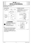
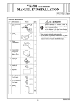
JS-505 Job Separator
INSTALLATION MANUAL
Applied Machines: C353/C253/C203
COLOR MFP (Color/B&W): 35 ppm/35 ppm, 25 ppm/25 ppm, 20 ppm/20 ppm
Product Code: A02E
I. Accessory parts
No.
Name
Shape
Q’ty
1. Job separator
After unpacking, be sure to get rid of the
packaging materials and keep them out of
the reach of children.
1
Putting the head in the plastic bag
involves danger of suffocation.
A083IXC001DA
2. Fixture A
1
A083IXC002DA
3. Fixture B
1
A083IXC003DA
4. Connector *
1
A083IXC004DB
5. Edge cover *
1
4551IXC008DA
6. Shoulder screw
1
A083IXC005DA
7. Screw A
(4 × 18 mm)
2
9J08IXC075DA
8. Screw B
(3 × 6 mm) *
3
A090IXC001DA
9. Installation
manual
1 set
4980IXC019DA
* The connector, edge cover and screw B are not
used for the machines.
E-1
A083-9550-00
II. Installation procedures
6. Use a flat-blade screwdriver and remove the
cover shown in the illustration.
1. Turn off the machine and unplug the power cord
from the power outlet.
2. Remove protective tape and shipping materials
and take out accessory parts.
3. Remove the protective vinyl bag from the hookup
cord.
A083IXC008DA
7. Fully screw down the shoulder screw furnished
with the job separator.
A083IXC013DB
4. Remove the sub tray of the machine.
* Remove it while pushing the claws of the sub tray
in the direction of the allow ➀ shown on the illustration and unhook.
➀
A083IXC009DA
8. Install the job separator.
Note:
When installing the job separator, align the Ugroove of the job separator with the shoulder
screw.
➀
A083IXC006DB
5. Peel seals off the machine (two seals).
A083IXC010DA
Seal
A083IXC007DA
E-2
9. Secure the job separator to the machine by the
fixture A (left) and fixture B (right)
(one screw A furnished with the job separator for
each of the fixture A and B).
Note:
• The fixture A with pieces of metal is required to
be attached to the left.
• When attaching each fixture, press it downward
and secure it with one screw.
A083IXC011DB
A083IXC014DA
10. Connect the hookup cord to the machine.
A083IXC012DB
E-3