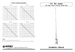
1
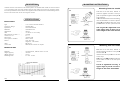
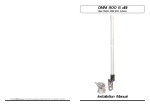
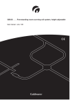
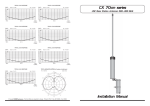
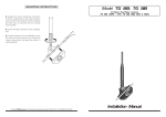
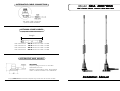
ALTERNATIVE CABLE CONNECTION
Model SKA 806-866
UHF Colinear Mobile Antenna 806-866 MHz
"ML" base / FME connection
Optional cables available.
OPTIONAL SPARE CABLES
(only "ML" / FME connection)
Length
code 2510305.00
code 2510405.00
code 2510505.00
code 2510605.00
0.5 m RG 58 C/U cable + 2 FME
1.5 m RG 58 C/U cable + 2 FME
3.5 m RG 58 C/U cable + 2 FME
5.0 m RG 58 C/U cable + 2 FME
ALTERNATIVE MAG MOUNT
CELL MAG:
Frequency Range: from DC to 1000 MHz
Overall Size: Ø 41 mm
Materials: Chromed Brass, Nylon, Silicon Rubber
Cable: 3 m RG 58 C/U MIL-C-17F / FME-female
Installation Manual
B Copyright SIRIO antenne - Technical Data are subjected to change - Printed in ITALY - Rev. 16/11/2004 - Cod. ID035
DESCRIPTION
Colinear antenna conceived for CELLULAR systems on 806-866 MHz. Made of black chromed
17/7 PH stainless steel whip and supplied with the "ML" (Micro Line) mount or magnetic mount
for a handy installation on the vehicle. The supplied cable is a RG 58 C/U in standard length of 5m
for the hole mount and 3m for the magnetic version.
MOUNTING INSTRUCTIONS
1.1
SPECIFICATIONS
Electrical Data
Type
Frequency Range
Impedance
Radiation
Polarization
Gain
Bandwidth at V.S.W.R. 2:1
V.S.W.R. at f. res.
Max Power
Feed System / Position
Mount
:
:
:
:
:
:
:
:
:
:
Cable
Connection
:
:
1/4 λ +5/8 λ Colinear Antenna
806-866 MHz
50 Ω Unbalanced
Omnidirectional
Vertical
3.5 dB ref. to a λ/4 whip
70 MHz
≤ 1.3 : 1
30 Watts CW
Direct / Base
hole: "ML" UHF
magnetic: "CELL MAG"
RG 58 C/U
FME female or other on request
2.1
Mechanical Data
Materials
Heigth (approx.)
Weight (approx.)
Mounting Hole
:
:
:
:
Chromed Brass, Stainless Steel 17/7 PH
360 mm
230 gr
∅ 14 or 18 mm
SKA 806-866
ID035
1.2
2.2
Mounting from the outside
1.1 Drill a 18 mm hole, deburr it and
protect it against corrosion. Loose part B,
push it upwards together with part C and
hold it tightly.
1.2 Insert the base into the mounting hole
and decentralize it. Insert the plastic fishplates D of part C into the hole. Screw on
part B with a 20 mm open-end wrench.
The ring nut B is tightened correctly,
if the upper edge of part A is at the
same height as the inner thread-bolt
Mounting from the inside
2.1 Drill a 14 mm hole, deburr it and
protect against corrosion. Loose part B and
use the item E.
Insert from below part F into the hole up
to the stop.
2.2 Push part A,B and E from above and
screw them on with a 20 mm open-end
wrench.
Part B is tightened correctly, if the
upper edge of part A is at the same
height as the inner thread-bolt.