1
CODE: 00ZUP3300VIME
POS TERMINAL
MODEL
UP-3300
("V" version)
CONTENTS
1. Removing the Rear display filter . . . . . . . . . . . . . . . . . . . . . . . . . . . . . . . . . . . . . . .2
2. Replacing the Rear display filter . . . . . . . . . . . . . . . . . . . . . . . . . . . . . . . . . . . . . . .2
3. Removing the Top cabinet . . . . . . . . . . . . . . . . . . . . . . . . . . . . . . . . . . . . . . . . . . .3
4. Replacing the Top cabinet . . . . . . . . . . . . . . . . . . . . . . . . . . . . . . . . . . . . . . . . . . .3
5. Removing the Power transformer, NF PWB and AC cord . . . . . . . . . . . . . . . . . . .3
6. Replacing the Power transformer, NF PWB and AC cord . . . . . . . . . . . . . . . . . . .3
7. Removing the LCD unit . . . . . . . . . . . . . . . . . . . . . . . . . . . . . . . . . . . . . . . . . . . . .4
8. Replacing the LCD unit . . . . . . . . . . . . . . . . . . . . . . . . . . . . . . . . . . . . . . . . . . . . .5
9. PS-RAM DISK : UP-P02MB2
. . . . . . . . . . . . . . . . . . . . . . . . . . . . . . . . . . . . . . . .5
10. RS232 I/F: ER-A7RS & EFT I/F ER-02EF . . . . . . . . . . . . . . . . . . . . . . . . . . . . . . .5
11. MCR UNIT: UP-E12MR2 . . . . . . . . . . . . . . . . . . . . . . . . . . . . . . . . . . . . . . . . . . . .6
12. DRAWER BOX UNIT: ER-03DW/04DW/05DW . . . . . . . . . . . . . . . . . . . . . . . . . . .6
13. REMOTE DISPLAY: UP-P16DP . . . . . . . . . . . . . . . . . . . . . . . . . . . . . . . . . . . . . . .6
14. HOW TO EXTEND DISPLAY POLE . . . . . . . . . . . . . . . . . . . . . . . . . . . . . . . . . . . 6
15. BUILT-IN PRINTER: UP-T80BP . . . . . . . . . . . . . . . . . . . . . . . . . . . . . . . . . . . . . . .8
16. SRN I/F: STANDARD . . . . . . . . . . . . . . . . . . . . . . . . . . . . . . . . . . . . . . . . . . . . . 12
17. RS232 I/F: STANDARD . . . . . . . . . . . . . . . . . . . . . . . . . . . . . . . . . . . . . . . . . . . .12
Parts marked with "!" is important for maintaining the safety of the set. Be sure to replace these parts with specified
ones for maintaining the safety and performance of the set.
SHARP CORPORATION
This document has been published to be used
for after sales service only.
The contents are subject to change without notice.
Precautions
•
•
•
•
•
•
Cautions on handling connectors
Before installation, be sure to turn off the power.
Use gloves to protect your hand from being cut by the angle
and the chassis.
Connect all the cables securely. When connecting or
disconnecting the cables, be careful not to apply stress to the
cables. (It may cause disconnection.)
Ground the human body to prevent against troubles and dust
adhesion to the LCD by static electricity. When assembling the
LCD, use a discharge blower to prevent against dust intrusion.
Be careful to the high voltage of the invertor PWB transformer.
Install the ferrite core onto the specified position of the cable
securely.
When connecting or disconnecting the following connectors, follow
the procedures below.
1)
PARTS NAME
PARTS CODE
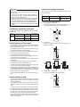
• How to Connect or Disconnect FFC
(1)
Open the slider to unlock position
The slider will open only up to a fixed height (about 1.2mm). If
you forcibly pull up the slider further, it may be dropped.
UNLOCK
Conditions for soldering circuit parts
Slider
To solder the following parts manually, follow the conditions
described below.
PARTS
NAME
Ceramic
oscillator
PARTS CODE
LOCATION
RCRMZ7002RCZZ
MAIN PWB:
X1 (8M)
MAIN PWB:
X2 (7.37M)
RCRMZ7004RCZZ
1.2mm
CONDITIONS FOR
SOLDERING
270°/3sec.
270°/3sec.
(2)
Note for handling of Touch panel
•
•
•
•
•
•
•
•
•
•
•
•
LOCATION
FFC
QCNCW7207RC4J MAIN PWB: CN6
CONNECTOR
TOUCH PWB: CN5
The transparency of the touch panel should be vitally important.
Do not put finger prints or water print on the surface. Use clean
finger such or gloves and masks.
For handling, do not hold the transparent area, and do not hold the
heat seal connector section to assure reliability.
Do not overlay touch panels. The edge may damage the surface.
Do not put a heavy thing on the touch panel.
Do not apply a strong shock, and do not drop it.
When attaching the protection film again, carefully check for no
dirt. If there is any dirt, it is transferred.
To clean dirt on the surface, use dry, soft cloth or a cloth immersed
in ethyl alcohol.
Insert the FFC
Insert the FFC firmly untill the FFC hits the bottom of the
connector’s insulator.
FFC
Check that the housing does not give stress to the touch panel.
Be careful not to touch the touch panel with tools.
The heat seal section is easily disconnected. Be careful not to give
a stress to the heat seal section when installing.
The touch panel is provided with an air groove to make the external and the internal air pressure equal to each other. If water or oil
is put around the air groove, it may penetrate inside. Be careful to
keep the air groove away from water and oil.
Input is performed with fingers. Do not use a hard thing for inputting.
FFC
FFC
CONNECTOR
(3)
FFC
CONNECTOR
Close the slider to lock position
Insert the FFC and then push the slider downward.
FFC
LOCK
Note for handling of LCD
•
•
•
•
•
•
Slider
The LCD elements are made of glass. BE careful not to give them
strong mechanical shock, or they may be broken. Use extreme
care not to break them.
If the LCD element is broken and the liquid is leaked, do not lick it.
If the liquid is attached to your skin or cloth, immediately clean with
soap.
Use the unit under the rated conditions to prevent against damage.
Be careful not to drop water or other liquid on the display surface.
The reflection plate and the polarizing plate are easily scratched.
BE careful not to touch them with a hard thing such as glass,
tweezers. Never hit, push, or rub the surface with hard things.
When installing the unit, be careful not to apply stress to the LCD
module. If an excessive stress is applied, abnormal display or
uneven color may result.
–1–
CONNECTOR
2)
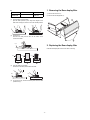
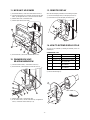
1. Removing the Rear display filter
PARTS NAME
FFC
CONNECTOR
PARTS CODE
LOCATION
QCNCW7217RC3J
1) Remove the two Screws 1.
2) Remove the Rear display filter 2.
TOUCH
PWB: CN1
• How to Insert FFC
(1)
Open the slider to unlock position
Open the slider upwards up to an angle of 60 degrees. If the
slider does not fully open, the FFC can not be smoothly inserted.
(2)
Insert the FFC
Insert the FFC firmly until the FFC hits the bottom of the
connector’s insulator.
FFC
2. Replacing the Rear display filter
Install the Rear display filter in the reverse order of removing.
FFC
FFC
CONNECTOR
(3)
FFC
(4)
FFC
CONNECTOR
CONNECTOR
Close the slider to lock position
Insert the FFC and then push the slider downward.
FFC
To pull out the FFC, unlock the slider to pull it out in the same
procedures as (1).
–2–
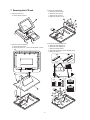
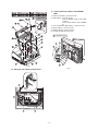
3. Removing the Top cabinet
1)
2)
2)
3)
4)
5)
•
•
5. Removing the Power transformer,
NF PWB and AC cord
Remove the two Screws 1.
Remove the Side cabinet 7.
Remove the Screw 2.
Remove the Printer cover 3.
Remove the Screw 4.
Remove the Top cabinet 8.
a) Lift the top cabinet and put it straight in the direction of arrow
A. ( Be careful not to pull the cable between the LCD I/F PWB
of the top cabinet and the MAIN PWB of the Bottom cabinet.)
b) Pull and remove the following cables between the LCD I/F
PWB of the top cabinet and the MAIN PWB of the Bottom
cabinet.
LCD Cable 5 : MAIN PWB : CN6
Earth wire 6.
7
1) Remove the Power transformer 1.
a) Remove the four Screws 2.
b) Remove the two Connectors 3.
2) Remove the NF PWB 4.
a) Remove the four Screws 5.
b) Remove the two Screws 6 and the three Earth wire 7.
c) Remove the NF angle unit 8.
d) Remove the Screw 9.
3) Remove the AC cord F.
a) Use a minus screwdriver to loosen the AC cord fixing screws
(2 pcs.) of the NF PWB 4 unit.
b) Remove the two screws G.
c) Remove the AC cord cover H.
d) Remove the AC cord F from the NF PWB 4.
1
A
1
8
4
5
6
3
2
4. Replacing the Top cabinet
6. Replacing the Power transformer,
NF PWB and AC cord
Install the top cabinet in the reverse order of removing. Before installing, make sure that each connector is connected securely.
Install the in the Power transformer, NF PWB and AC cord in the
reverse order of removing.
Before installing, make sure that each connector is connected securely.
* When connecting the AC cord to the power supply unit in
assembly, tighten with the torque of 3 kg/cm ± 1 kg/cm.
–3–
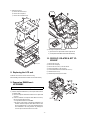
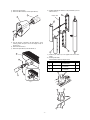
3) Remove the Inverter PWB 5.
a) Remove the Inverter cable 6.
b) Remove the CCFT cable 7.
c) Remove the two screws 8.
d) Remove the Inverter cover 9.
7. Removing the LCD unit
1) Remove the LCD unit 1.
a) Remove the four Screws 2.
1
2
2
4) Remove the Touch panel PWB unit F.
a) Remove the LCD cable(40P) G.
b) Remove the LCD cable(30P) H.
c) Remove the Inverter cable I.
2) Remove the LCD rear cabinet 3.
a) Remove the two Screws 4.
b) Remove the pawls a to 1 of the LCD rear cabinet 3 in that
order.
d) Remove the two Screws J and the two Earth wire K.
e) Remove the Screw L.
–4–
5) Remove the LCD M.
a) Remove the five Screws N.
b) Remove the LCD plate O.
c) Remove the LCD PWB unit P.
A
1
18
19
18
18
18
20
17
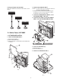
3) Removing the Expansion RAM Board.
a) Open the arms of option RAM connector right and left.
b) The Expansion RAM Board will be lifted automatically.
10. RS232 I/F: ER-A7RS & EFT I/F:
ER-02EF
1)
2)
2)
3)
4)
5)
6)
Touch panel
8. Replacing the LCD unit
Install the LCD unit in the reverse order of removing.
Before installing, make sure that each cables are connected securely.
9. Expansion RAM Board :
UP-P02MB2
Make sure to save data before installing this option
1) Remove the top cabinet.
2) Install the Expansion RAM Board 1 to the Option RAM connector
on the Main PWB.
a) Insert the Expansion RAM Board aslant into the option RAM
connector.
b) Push the RAM disk unit Expansion RAM Board is locked by
the arms of option RAM connector.
* It is possible to install one UP-P02MB2.
* Be careful of the direction of Expansion RAM Board to be
installed. Install the Expansion RAM Board with the notch
part of the PWB (Figure A) come right. Installing the Expansion RAM Board in the wrong direction may damage the
connector part or make the machine out of order.
–5–
Remove the rear cover.
Remove the rear display.
Remove the two screws 1 from the shassis.
Insert the I/F PWB 2 to the connector.
Fix the I/F BRACKET to the shassis with screws 1.
Install the ferrite Core 3.
Install the Nylon band 4 to the cables.
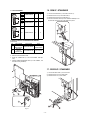
11. MCR UNIT: UP-E12MR2
13. REMOTE DISPLAY
1) Fix the MCR ANGLE 1 to the lower cabinet with two screws 2.
2) Connect the MCR cable 3 to the MCR connector with the cable
holder 6, and tighter the screw 7 on the back of lower cabinet.
3) Install the ferrite Core 4 to the MCR cable.
4) Install the Nylon band 8 to the cable.
When the remote display is installed, service resetting is required.
1) Connect to the Display cable 1 to the display connector 2.
2) Fix the earth wire 3 from the display unit with screw 4.
4
2
1
3
14. HOW TO EXTEND DISPLAY POLE
The pole can be extended by installing the attached pole to the
standard pole.
COMPONENT LIST:
5) Fix the earth wire 5 from the UP-E12MR2 with the screw.
No.
NAME
G
Pole cabinet
H
I
12. DRAWER BOX UNIT:
ER-03DW/04DW/05DW
J
1) Connect the drawer cable 1 to the drawer connector 2.
2) Fix the earth wire 3 from drawer box unit with the screw 4.
K
1
3) Install the ferrite Core 5 to the drawer cable.
4) Fix the drawer cable 1 with the cable holder 6, and tighten the
screw 7 on the back of lower cabinet A or B.
1
–6–
Q’ty
2
Screw (M2 × 8)
Pole connection
4
Screw (M4 × 16)
Securing the UP-P16DP to
the wooden table
4
Screw (M4 × 20)
Securing the UP-P16DP to
the metal table
4
Nut
Securing the UP-P16DP to
the metal table
4
1) Remove the five screws 1.
2) Remove the Base angle 2.
2
USE
Pole extension
3) Remove the two screws 6.
4) Remove the Base cabinet 4 from the pole cabinet 7.
8) Install the attached pole cabinet G to the pole cabinet 7 to fix it
with the screw H.
7
7
Display cable
4
7
12
12
6
5) Turn the ratchet 9 connected to the pole cabinet 7 to the
removing position and pull it out from the display unit 8 as
shown in Fig. A.
6) Remove the two screws F.
7) Remove the pole cabinet 7 from the Ratchet 9.
11
11
8
9) Install the pole cabinet G in the opposite order of the disassembly.
10) Fastening onthe table:
Secure the Base cabinet 2 using the screw.
10
No.
I
J
9
K
NAME
Screw (M4 × 16)
Screw (M4 × 20)
Nut
USE
Securing the UP-P16DP to
the wooden table
Securing the UP-P16DP to
the metal table
Securing the UP-P16DP to
the metal table
13
7
13
10
9
Fig. A
14
14
15
–7–
15
Q’ty
4
4
4
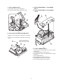
2. Install the PS+CONTROL PWB 6.
Lowering the height of the UP-P16DP
Remove the standard Pole and attach the Base cabinet 4 to the
Ratch 9.
CAUTION: The power supply unit is an important item. Make sure
that the unit code is RDENC 1010RCZZ.
1) Fix the PS+CONTROL PWB 6 with three SCREWs 7 Z, 3
* SCREW 3: Use the screw which was fixing the CLAMP 4
* SCREW Z: fix the screw with earth WIRE.
3. Connect the POWER SUPPLY CABLE 5 to the
PS+CONTROL PWB 6. (No. CN1)
4. Connect the I/F CABLE 8 of the PS+CONTROL
PWB 6 to the UP-3300 MAIN PWB (No.CN20)
15. Built-in Printer: UP-T80BP
1. UP-T80BP INSTALLATION
1. Remove the BOTTOM PLATE 2.
1) Remove the three SCREWs 1.
2) Remove the BOTTOM PLATE 2.
3) Remove the SCREW 3, CABLE CLAMP 4 and POWER SUPPLY CABLE 5.
Fig. 2
2
5. Remove the PRINTER LID 9.
1) Remove the screw F.
2) Remove the PRINTER LID 9.
6. Install the four PAPER ROLLERs G.
9
11
1
4
3
5
Fig. 1
10
Fig. 3
–8–
7. Install the SWITCH UNIT H.
9. Install the PAPER GUIDE M to the PRINTER
UNIT N.
1) Fix the SWITCH UNIT H on the cabinet pawl A.
2) Pass the SWITCH UNIT CABLE I through the hole (B).
10. Install the HEAD CABLE O to the PRINTER
UNIT N.
12
17
12
19
A
13
B
A
Fig. 4
8. Install the AUTO CUTTER RELAY PWB UNIT J.
1) Install the AUTO CUTTER RELAY PWB UNIT J with SCREW
K.
2) Pass the AUTO CUTTER RELAY PWB CABLE L through the
hole C.
15
15 : XEBSD30P08000
16
18
C
14
Fig. 6
11. Install the PRINTER UNIT N.
1) Connect the AUTO CUTTER CABLE P to the AUTO CUTTER
RELAY PWB J.
2) Pass the HEAD CABLE O through the hole (C).
3) Pass the MOTOR CABLE Q and SENSOR CABLE R through
the hole (D).
4) Open the PRINTER UNIT N.
5) Fix the PRINTER UNIT N with four SCREWs S
* Fix the SCREWs S in the order of S-a to S-d.
6) Fix the two EARTH WIREs T with a SCREW U.
Fig. 5
–9–
13. Connect the Printer cables to the CONTROL
PWB.
1) SWITCH UNIT CABLE I: Connect to the CN7.
2) HEAD CABLE O: Connect to the CN5.
Attach the FERRITE CORE V and CABLE
CLAMP 4.
Fix the CABLE CLAMP 4 with a SCREW
X.
3) AUTO CUTTER RELAY PWB CABLE L: Connect to the CN4.
4) MOTOR CABLE Q: Connect to the CN2.
5) SENSOR CABLE R: Connect to the CN6.
6) I/F CABLE 8: Attach the Ferrite core [.
28 : XEBSD30P08000
28
4
26
16
21
19
13
22
Fig. 7
Fig. 8
12. Wiring for each cables as shown below
20
14
16
19
– 10 –
14. Wiring for each cables as shown below
Fig. 9
15. Install the BOTTOM PLATE 2.
16. Install the PRINTER COVER Y.
29
2
1
Fig. 11
Fig. 10
– 11 –
1. LIST FOR SCREWs
No.
K
Z
X
S-a
S-b
S-c
L
S-d
M
PARTS CODE
M [mm]
L [mm]
XEBSD30P08000
3
8
XEBSD26P06000
2.6
6
XEBSD26P08000
2.6
8
XHBSD30P06000
3
8
16. SRN I/F: STANDARD
1)
2)
3)
*
Connect to the SRN cable 1 to the SRN connector 2.
Install the Ferrite core 3 to the SRN cable 1.
Install the Nylon band 4 to the SRN cable 1.
Connect the terminal resistor (50 ohm: QCNCM7145RCZZ) to the
POSs at both ends and in front of the SRN in-line system.
7
L
U
M
2. INSTALLATION OF PAPER NEAR END SENSOR
[PARTS LIST]
No.
PARTS NAME
PARTS CODE
NOTE
1
PAPER NEAR
END SENSOR
DUNTK3819BHZZ
SENSOR UNIT,
FIXING SCREW
2
NEAR END
SENSOR
CONNECTOR
QCNCM6865RC0B
2 pin connector
1. Remove the BOTTOM PLATE .
2. Remove the PS+CONTROL PWB .
3. Solder the CONNECTOR 1 to the PS+CONTROL PWB (No.
CN1)
4. Install the NEAR END SENSOR UNIT 2 to the CABINET , and
fix it with the fixing SCREW 3.
17. RS232 I/F: STANDARD
1) Connect the RS232 cable 1 to the connector.
2) Install the ferrite Core 2 to RS232 cable.
3) Install the ferrite core 3 to the cables.
2
3
1
Fig. 12
– 12 –
q
COPYRIGHT 1999 BY SHARP CORPORATION
All rights reserved.
Printed in Japan.
No part of this publication may be reproduced,
stored in a retrieval system, or transmitted.
In any form or by any means,
electronic, mechanical, photocopying, recording, or otherwise,
without prior written permission of the publisher.
SHARP CORPORATION
Information Systems Group
Quality & Reliability Control Center
Yamatokoriyama, Nara 639-1186, Japan
1999 March Printed in Japan T