1
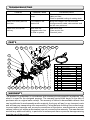
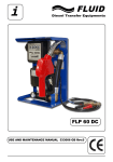
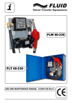
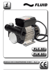
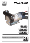
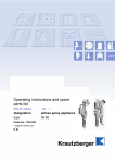
i FLUID FLC 60 FLK 60 USE AND MAINTENANCE MANUAL 533002 GB Rev.0 INDEX Safety Information _________________________________________________ pag. 2 Declaration of Conformity ___________________________________________ pag. 3 Technical Specifications ____________________________________________ pag. 3 Installation _______________________________________________________ pag. 4 Use ____________________________________________________________ pag. 6 Maintenance _____________________________________________________ pag. 6 Troubleshooting __________________________________________________ pag. 7 Parts ___________________________________________________________ pag. 7 Warranty ________________________________________________________ pag. 7 SAFETY INFORMATION The following safety alert symbols are used in this manual. Obey all safety messages that follow this symbol to avoid possible injury or death. indicates an imminently hazardous situation which will result in DANGER! death or serious injury if not avoided. indicates a potentially hazardous situation which will result in WARNING! death or serious injury if not avoided. It is responsibility of the person that use the pump to: -) Know and follow applicable national and local safety rules pertaining to installing and operating electrical equipment for use with petroleum fluids. -) Know and follow adequate safety precautions when handling petroleum fluids. -) Insure that all operators have access to adequate instructions concerning safe operating and maintenance procedures. This pump is designed for automotive Diesel fuel only. The pump is DANGER! not suitable for food substances transferring. The motor of the pump is not explosion proof, do NOT USE the pump in ambient with flammable vapours. Do NOT USE the pump whit gasoline, petrol or other flammable liquids with flash points less than 55°C (131°F), DO NOT use this pump to transfer Diesel fuel when ambient temperature exceeds the Diesel flash point temperature 55°C (131°F). DO NOT operate the pump in the presence of any source of ignition including running or hot engines, lighted cigarettes or gas or electric heaters. For safe operations, the diesel fuel transfer system must be properly grounded, this means a continuous metal to metal contact between components, supply tanks, pump, hose, metal nozzle and receiving tank. Failure to follow the above mentioned instructions may rsult in death or serious injury from fire or explosion. WARNING! This manual is integrating part of the pump. Before starting, in the way to get the best results and the maximum performance from the pump, please read carefully these operating instructions and store the manual in a safe place. Don’t leave the running pump unwatched , when the pump is not in use, store it in a safe place out of reach of children. Insulation Class 1 I- The unit may only be connected to properly earthed power source, into a socket which is protected by a circuit breaker , with respect of national and local safety rules. When the pump is not in use and before of any maintenance, installation or inspection, disconnect the pump from the power supply. To disconnect the plug do not pull the cable, but remove directly the plug/clamps; don’t touch plug/clamps/switches with wet hands.It’s forbidden modify any part of the pump. Prevent any injury observing the basic safety rules. Use the pump for Diesel transferring only: a misuse of the pump can results dangerous for people, wares and/or animals. During the transferring operation, pay attention to avoid 2 any splash of Diesel; Avoid prolonged contact with Diesel fuel. It’s recommendet the use of protective glasses, gloves and aprons in case of splashing or spiling. Before of use, chek always that the pump is in order: if any problem is found don’t use the pump and solve the problem and, if necessary, contact the service. Never point the Diesel jet at electrical equipment, cables, open flames, hot object, persons, animals, wares or other place different from the receiving tank. DECLARATION OF CONFORMITY We: FLUID s.r.l. via G. Fucà, 119 41100 Modena - ITALIA herewith declare that the construction of the pumps FLC 60 - FLK 60 - FLD 60 - FLW 60 - FLT 60 complies with the following relevant regulations: 89/392 - 91/368 - 93/44 - 92/31 - 89/336C - 93/68 - 73/23 complies with the following relevant standards: EN 292/1 EN 50081-1 EN 60335-1 EN 292/2 EN 50081-2 EN 294 EN 55014 complies with the following national standards: DPR 547/55 Modena, lì 15/09/2007 Legal Rappresentative Giovanni Bedoni TECHNICAL SPECIFICATIONS Self- priming rotary vane pump, equipped with by-pass valve and filter integreted in the pump body, driven by a asincronuos motor 230-50/60Hz, in protection class IP 54, designed for the transfer of Diesel fuel. The motor is provided with an automatic thermal protection switch that switch off the pump in overload running conditions. The thermal protection switch on automatically after few minutes and, if the main switch of the pump is still turned ON, the motor will re-start spontaneously: for this reason it’s recommended always switch off the pump after an unexpected stop of the motor and contact immediatly the service. The pump is designed for a continuous use S1. FLC 60: 230V-50/60Hz pump, with supply cable, switch and fixing facility. FLK 60: kit with FLC 60 pump,1“ suction hose, ¾“ antistatic delivery hose and nozzle with swivle connector. Noise level Under normal working conditions, the noise emission pression do not exceed the value of 70 dB at the distance of 1 meter from pump. 3 Type V-Hz (V +/-5% Hz +/-2%) Power max W Current nom. A Thermal protect. Port Weight Kg FLC 60-230 230-50 460 1.5/1.95 ● 1” 6.5 Diesel fuel flow To get the maximun pump flow rate it’s necessary: -) Minimize lenght of suction and discharge lines; -) Avoid, if possible, elbow and throttling along the line; -) Use tubing with diameter equal or grater than 3/4”; -) Keep clean the strainer regularly; -) Use extension cable only if necessary (minimum section 3x2.5 mmq x 5m). Flow (Liters/min) Pistola autom. Pistola autom. + Contalitri Delivery hose lenght (meters) Product identification Serial Number Product Description Dimensions Date of Production FLC 60 Technical Data INSTALLATION If the application is for gasoline, petrol or fluids that require an exploDANGER! sion-proof product, DO NOT INSTALL THIS ELECTRIC PUMP. 4 Preliminary operations: -) Check that the product has not suffered any damage during transport or storage, in case of damages or missing parts, please contact immediately the dealer. -) Remove the protection plugs on inlet and outlet of the pump; -) Attach the pump using screws of adequate diameter for the fixing holes provided in the bracket of he pump. Electrical connections WARNING! It’s responsibility of the installer to perform the electrical connections with respect for the applicable local or national regulations. -) Check that the suppling electrical specifications correspond to those shown on the plate. failure in the electrical specifications respect could damage the electrical pump; Preserve the supply cable from oil, high temperatures and cutDANGER! ting edges. Inspect always the supply cable against damages: in case of damage replace immediatly the supply cable with an original one. Avoid that cables, electrical receptacle, clamps and switches have contact with water or flammable fluids and avoid high moisture ambient for the pump. If necessary, use extension cable 5 meters lenght with minimum section 3x2.5mmq, unwinding completely the extension cable.All metal parts must be always grounded. Tubing connection Before connection make sure that the tubing, the inlet - outlet of the pump and the suction tank are not clogged and free of dirt, rust, etc. that could damage the pump and/or clog the retainer. The threaded connections must be 1” BSP type (do not use conical threaded joints that could damage the threaded pump bores), the pipes connections must be leakage-proof, to avoid air or fuel leakage and pump trouble. When the hoses are not supplied, it is consiled minimize the lenght of both suction and discharge hoses, use hoses with adequate characteristics for diesel fuel, antistatic, with diameter equal or greater than ¾” and working pressure equal or grater than10 bar, in addition the suction hose shall be suitable for functioning under suction pressure. Connect the pump, observing the right fuel flow, like indicated by the arrows on the pump body. The use of tubing unsuitable for use with Diesel fuel can damage WARNING! the pump, injury persons and produce pollution, because of diesel fuel splashing/spilling. The discharge hose and the accessories (nozzle, meter, etc.) WARNING! must be grounded (to dissipate the electrostatic currents), alternatively the hoses can be of antistatic type). It is installer responsability to use tubing with adequate characteristics. USE DANGER! To prevent injury, observe precautions against electrical shock, fire or explosion when dispensing fuel. Do not operate switch with wet handsDo not operate the pump in the presence of any source off ignition including running or hot engines, lighted cigarettes or gas or electric heater. Start the diesel fuel dispensing turning ON the switch on the pump and opening the delivery valve (the lever of the nozzle, if present) solidly grasping the end of the hose; at the end of the diesel fuel dispensing turn OFF the switch on the the pump and disconnect the main power supply. WARNING! Operate the pump in ambient with temperature between -15°C and +40°C. Serious or fatal shock can result from operating electrical equipment in dump or wet locations. 5 WARNING! Avoid prolonged contact with petroleum fuels. Use protective goggles, gloves and aprons in case of splashing or spills. Change saturated clothing and wash skin promptly with soap and water. This pump is designed for the transfer of diesel fuel with flash point at or above 55 °C (131°F). DO NOT USE this pump for other types of fluid. Use of this pump with other types of fluid may damage components and will void the warranty. The pump in not suitable with alimentary or food fluids. Operation without fluid DO NOT LEAVE the pump running without fuel. Dry running WARNING! (even for few minutes only) can damage the pump. Operating in by-pass Pump is equipped with an automatic by-pass valve. Pump wil go into by-pass when the discharge line is close.To prolong the life of the pump, minimize time spent in by-pass. Operation with the discharge line closed -by-pass mode- is alDANGER! lowed for maximum 3 minutes only. Longer pump running in by-pass mode produce abnormal diesel fuel temperature raising, with all the fire or explosion risks connected. MAINTENANCE WARNING! Observe precaution against electrical shock when servicing the pump! Always disconnect power before attempting any service. Never apply electrical power to the pump when any of the cover plates are removed. The pump is designed for minimal maintenance, it is recommended observe the following indications: Daily: Keep the pump exterior clean to help identify leaks, check the connection/joints sealing and repair immediatly any leakage, if necessary. Check the electrical cable conditions: if damages/cuts or other defects are recognized, it is necessary replace the cable with an original one, this operation must be performed by an expert technician. Check the conditions of suction and discharge hoses: if fissures, cuts, bulges or other damages are recognized, it is necessary replace the hose with an original one. Weekly or every 5 hours of work: Inspect and/or clean the strainer integrated in the body pump: a clogged retainer reduce the fuel flow delivery and the pump lifetime; to disassemble the retainer unscrew the plug (2, pag. 7) and remove the strainer from its seat, clean by air -blast spray, then reassemble the strainer and the plug. Every 2 years it’s recommended replace the discharge hose. Transport Switch off the pump, disconnect the electrical wiring, disconnect the lines and flush the pump. Package properly the product and be care to avoid shocks during the transportation. Disposing of contamined materials Don’t disperse contamined parts into the environment. Refer to local regulations for proper disposal of the product. 6 TROUBLESHOOTING Troubles Possible Cause Corrective Action Motor does not run No electrical power to pump Check electrical connections, extension cable and fuse. Chek for possible locking of rotating shaft Motor runs slowly and low fuel flow Low voltage in the electric line Bring the voltage in the corrrcts limits IUsing extension cable, cble sections shall be 2x4 mmq minimum. Motor runs, but no fuel delivery Tank level low Clogged suction line Air leak in system Add fuel to tank Clean suction line Check all joints PARTS FLC 60 PARTS Pos. Q.ty Description. P/N 695005 1 1 Cover + screw 1 695001 Gaskets kit 2 695002 1 Rotor + vanes kit 3 210002 Pump body 60 lt. 1 4 695003 5 1By-pass valve kit 217001 Strainer 6 1 310201 230V-50/60Hz motor 7 1 695006 Electrical box kit 8 1 9 1 425001 Switch 10 1 410001 Cord 3x0.75 Schuko 11 1 Capacitor 12.5 mF 440001 Bearing 6201-12x32x10 310201 2 12 695007 Fan + cover kit 1 13 WARRANTY The product is guaranteed in accordance with statutory/country-specific regulations, only when it is used for the designed purpose. The warranty period shall begin on the date of purchase with an original sales receipt. The warranty is limited to demostrable defects that can be attributed to workmanship and/or material; the buyer will pay for any transport costs and will bear any transporting risks responsibilty. Failure/defects resulting from normal wear, incorrect and/or improper use, erroneus connections of the device, manomissions or modifications (without our written authorization) are not covered by the warranty. The manufacturer exclude any additional liability, in particular for subsequent ware or persons damages arising from the use of the product. 7 Timbro Rivenditore - Dealer’s stamp FLUID s.r.l. via G. Fucà, 119 ZI Torrazzi Sud 41100 Modena (MO) Italy Tel. +39 059 250307 Fax +39 059 250307 e-mail: info@fluiditalia.it www.fluiditalia.it Pictures and descriptions are FLUID srl properties. Technical datas and characteriscs indicated are intended not binding and FLUID srl could change them without any advanced notice. 05/08 Printed in Italy Fuel Transfer Equipment