1
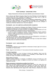
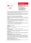
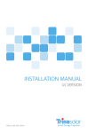
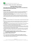
INSTALLATION MANUAL AND SAFETY INSTRUCTIONS Rev.6 HF Energy PHOTOVOLTAIC MODULES FAMILY Installation Manual and Safety Instructions , Table of Contents Table of Contents .............................................................................................................. 1 1. Introduction ................................................................................................................. 1 1.1. Disclaimer of Liability ............................................................................................ 1 1.2. International Electrotechnical Commission (IEC) Listing Information ................... 1 1.3. Limited Warranty .................................................................................................. 1 1.3.1. Limited Product Warranty: Fifteen (10) Year Repair, Replacement or Refund Remedy ...................................................................................................................... 1 1.3.2. Limited Power Warranty ................................................................................. 1 1.3.3. Exclusions and limitations .............................................................................. 2 1.3.4. Limitation of Warranty Scope ......................................................................... 2 1.3.5. Obtaining Warranty Performance ................................................................... 3 2. General Safety............................................................................................................ 4 2.1. Safety Precautions ............................................................................................... 4 2.2. Packing removal and temporary storage .............................................................. 4 3. Installation .................................................................................................................. 5 3.1. General ................................................................................................................. 5 3.2. Notes on Installation ............................................................................................. 5 3.3. Module Mounting .................................................................................................. 5 3.3.1. Site Considerations ........................................................................................ 5 3.3.2. Mounting Configurations ................................................................................ 5 4. Wiring ......................................................................................................................... 8 4.1. General Wiring ...................................................................................................... 8 4.2. Grounding ............................................................................................................. 8 4.3. Series Connection ................................................................................................ 8 4.4. Parallel Connection .............................................................................................. 8 5. Maintenance ............................................................................................................... 9 6. Specifications ........................................................................................................... 10 “HF ENERGY” is a trademark of “HF ENERGY srl”, Italy The content of this manual may be changed without prior notice. Rev. 6 Installation Manual and Safety Instructions , 1. Introduction This manual provides information for “HF ENERGY” photovoltaic (PV) modules. Serial number : 1YYMM00001 (~99999) (Ex. 1130100004) 1 – production site ( factory in Varazdin-Croatia) YYMM : Production year and month 00001~99999 : Production number This document is applicable to the 60 cells polycrystalline and monocrystalline series of solar modules. Important! Read this instruction sheet in its entirety before installing, wiring or using this product in any way. Failure to comply with these instructions will invalidate “HF ENERGY” Limited Warranty for PV module. 1.1. Disclaimer of Liability The installation techniques, handling and use of this product are beyond company control. Therefore, “HF ENERGY” does not assume responsibility for loss, damage or expense resulting from improper installation, handling or use. 1.2. International Electrotechnical Commission (IEC) Listing Information This product meets all requirements listed by IEC 61215 edition 2 for terrestrial PV modules. The IEC standard covers flat-plate PV modules and panels intended for installation on buildings and those intended to be freestanding. This product is not intended for use where artificially concentrated sunlight is applied to the module. 1.3. Limited Warranty 1.3.1. Limited Product Warranty: Fifteen (10) Year Repair, Replacement or Refund Remedy “HF ENERGY srl” , warrants that for ten (10) years from the date of delivery its Photovoltaic modules (PV modules) shall be free from defects in materials and workmanship under normal application, installation, and use and service conditions. If the PV modules fail to conform to this warranty, then for a period ending ten (10) years from date of delivery to the original end-customer (the Customer), “HF ENERGY” will, at its option, either repair or replace the product, or refund the purchase price as paid by the Costumer. The repair, replacement or refund remedy shall be the sole and exclusive remedy provided under the Limited Product Warranty and shall not extended beyond the ten (10) year period set forth herein. This Limited Product Warranty does not warrant a specific power output, which shall be exclusively covered under clause 2 hereinafter (Limited Power Warranty). 1.3.2. Limited Power Warranty “HF ENERGY” additionally warrants: if, within twelve (12) years from date of delivery to the Costumer any PV modules exhibit a power output less than 90% of the Minimum Peak Power as specified in “HF ENERGY” Product datasheet, provided that such loss in power is determined by “HF ENERGY” (at its sole and absolute discretion) to be due to defects in material or workmanship, “HF ENERGY” will replace such loss in power by either providing to the Costumer additional PV modules to make up such loss in HF Energy is a trademark of “HF Energy srl”, Italy The content of this manual may be changed without prior notice. Page 1 of 10 Rev. 6 Installation Manual and Safety Instructions , power or by providing monetary compensation equivalent to the cost of additional PV modules, at the option of “HF ENERGY”. Minimum Peak Power, if not expressed directly in “HF ENERGY” Product Datasheet, is defined as Nominal Power minus Power Tolerance. “HF ENERGY” additionally warrants: if, within twenty five (25) years from date of delivery to the Costumer any PV modules exhibit a power output less than 80% of the Minimum Peak Power as specified at the date of delivery in “HF ENERGY” Product datasheet, provided that such loss in power is determined by “HF ENERGY” (at its sole and absolute discretion) to be due to defects in material or workmanship, “HF ENERGY” will replace such loss in power by either providing to the Costumer additional PV modules to make up such loss in power or by providing monetary compensation equivalent to the cost of additional PV modules, at the option of “HF ENERGY”. Minimum Peak Power, if not expressed directly in “HF ENERGY” Product Datasheet, is defined as Nominal Power minus Power Tolerance. 1.3.3. Exclusions and limitations Warranty claims must in any event be filed within the applicable Warranty period. Warranty claims may only be made by, or on the behalf of, the original end customer or a person to whom title has been transferred for the PV modules. The Limited Warranties do not apply to any of the following: PV modules witch in “HF ENERGY” absolute judgment have been subjected to: misuse, abuse, neglect or accident; alteration, improper installation, application or removal (including but not limited to installation, application or removal by any party other than “HF ENERGY” authorized dealer; nonobservance of “HF ENERGY” installation manual, users and/or maintenance instructions; repair or modifications by someone other than an approved service technician of “HF ENERGY”; power failure surges, lighting, flood, fire, accidental breakage or other events outside “HF ENERGY” control). Cosmetic defects originating from normal wear and tear of PV module materials while in use. PV modules installed in locations, which in “HF ENERGY” absolute judgment may be subject to direct contact with salt water. The Limited Warranties do not cover any transportation costs for return of the PV modules, or for reshipment of any repaired or replaced PV modules, or cost associated with installation, removal or reinstallation of the PV modules. When used on a mobile platform of any type, the Limited Power Warranty, applying to any of the PV modules shall be limited to twelve (12) years as per provisions of clause 1.3.2 hereof. Warranty claims will not apply if the type or serial number of the PV modules is altered, removed or made illegible. 1.3.4. Limitation of Warranty Scope Subject to the limitations under applicable law, the limited warranties set forth herein are expressly in lieu of and exclude all other express or implied warranties, including but not limited to warranties of merchantability and of fitness for particular purpose, use or application, and all other obligations or liabilities on the part of “HF ENERGY”, unless such other warranties, obligations or liabilities are expressly agreed to in writing signed and approved by “HF ENERGY”. “HF ENERGY” shall have no responsibility or liability whatsoever for damage or injury to persons or property or for other loss or injury resulting from any cause whatsoever arising out of or related to the product, including, without limitation, any defects in the module, or form use or installation. Under no circumstances shall “HF ENERGY” be liable for incidental, consequential or special damages, howsoever caused. Loss of use, loss of profits, loss of production, loss of revenues are therefore specifically but without limitation excluded. “HF ENERGY” aggregate liability, if any, in damages or otherwise, shall not exceed the purchase price paid to “HF ENERGY” by the Customer, for the unit of product or service furnished or to be furnished, as the case may be, which gave rise to the warranty claim. HF Energy is a trademark of “HF Energy srl”, Italy The content of this manual may be changed without prior notice. Page 2 of 10 Rev. 6 Installation Manual and Safety Instructions , In jurisdiction not allowing limitations on implied warranties or the exclusion of damages, the above limitations or exclusions may not be applicable. 1.3.5. Obtaining Warranty Performance If you feel you have a justified claim covered by this Limited Warranty, immediately notify the (a) Installer, who sold the PV-modules, or (b) any authorized “HF ENERGY” distributor, of the claim in writing, or (c) send such notification to “HF ENERGY” directly. In addition, please enclose evidence of the date of delivery of the PV module. If applicable, your installer or distributor will give advice on handling the claim. If further assistance is required, please write to “HF ENERGY” for instructions. The return of any PV modules will not be accepted unless prior written authorization has been given by “HF ENERGY”. HF Energy is a trademark of “HF Energy srl”, Italy The content of this manual may be changed without prior notice. Page 3 of 10 Rev. 6 Installation Manual and Safety Instructions , 2. General Safety 2.1. Safety Precautions Danger! PV modules are sources of voltage when exposed to light. Module interconnects pass direct current (DC) when the module is under load. Do not connect or disconnect modules when they are under load! Direct current can arc across gaps and may cause injury or death if improper connection or disconnection is made, or if contact is made with module leads that are frayed or torn. Before installing this device, read all safety instructions in this manual! Cover all modules in the PV array with an opaque material before making or breaking electrical connections. All installations must be performed in compliance with all applicable regional and local codes. Do not attempt to repair any part of the module. Do not try to disassemble the module. Do not use modules that are damaged (e.g.: front glass is broken or back sheet is torn) Do not open the junction box on the back side of the module. Contact your module supplier if maintenance is necessary. Installation should be performed only by authorized personnel. Use only equipment, connectors, wiring and supporting constructions designed for use in photovoltaic systems. Remove all metallic jewelry prior to installing this product to reduce the chance of accidental exposure to live circuits. Use insulated installation tools to reduce risk of electrical shock. Do not stand on, drop, scratch or allow objects to fall on modules. To avoid damage to the backsheet, do not scratch or hit the backsheet. Do not drill holes in the frame, as this can compromise the frame strength and cause corrosion of the frame. Do not scratch the frame as this may remove the anodized coating of the frame and cause corrosion of the frame. Do not use junction box or connecting wires for transportation help or for holding the module. Do not treat the back side of modules with paint, glue or sharp objects. If the front glass is broken or the back sheet is torn, contact with any module surface or module frame can cause electric shock. Do not install or handle the modules when they are wet or during periods of high wind. “HF ENERGY” modules have been qualified for Application Class A Save these instructions for later reference in an easy reachable place. 2.2. Packing removal and temporary storage Modules must be stored in dry and ventilated spaces. Leave modules unpacked in their original packing until you are ready to install them. Carry the modules with both hands. Do not put weight on the modules. Do not remove any identification labels from the modules. If storing uninstalled modules outdoors for any period of time, always cover the modules and ensure that the glass faces down to stop water from collecting inside the module and on top of the glass. HF Energy is a trademark of “HF Energy srl”, Italy The content of this manual may be changed without prior notice. Page 4 of 10 Rev. 6 Installation Manual and Safety Instructions , 3. Installation 3.1. General Before install and operate, this manual must be well understood. 3.2. Notes on Installation A gap between PV module frame and installation object is necessary for cooling air circulation. Do not seal this gap. The recommended standoff height is minimum 10 cm (4 inch). 3.3. Module Mounting “HF ENERGY” Limited Warranty for PV Modules is contingent upon modules being mounted in accordance with the requirements described in this section. 3.3.1. Site Considerations “HF ENERGY” modules should be mounted in locations that meet the following requirements: Operating Temperature: All “HF ENERGY” modules must be mounted in environments that ensure operation within the following maximum and minimum operating temperatures: Maximum Operating Temperature: Minimum Operating Temperature: + 85˚C - 40˚C Care should be taken to provide adequate ventilation behind the modules, especially in hot environments. Design Strength: “HF ENERGY” modules are designed to meet a maximum positive (or upward, e.g. wind) and negative (or downward, e.g. static load) load of 2400 Pa (Pascal; 2400 kg/m2) and snow load of 5400 Pa when mounted in one of the mounting configurations specified in section 3.3.2. When mounting modules in snow prone or high wind environments, special care should be taken to mount the modules in a manner that provides sufficient design strength while meeting local code requirements. Excluded Operating Environments: Certain operating environments are not recommended for specific “HF ENERGY” modules and are excluded from the “HF ENERGY” Limited Warranty for these modules. 3.3.2. Mounting Configurations Modules may be mounted at any angle from horizontal to vertical. Select the appropriate orientation to maximize sunlight exposure. Specific information on module dimension and the location of mounting and grounding holes is provided below (Figure 4). We recommend that PV modules are mounted at a minimum tilt angle of 6° with respect to the horizon, in order to facilitate the self-cleaning of their front glass from dirt during ordinary raining. In order to prevent water from entering the junction box, which could present a safety hazard, modules should not be mounted in manner that the front/top glass faces downward (e.g. on a tracking structure that positions the module with the junction box facing skyward during sleep mode). HF Energy is a trademark of “HF Energy srl”, Italy The content of this manual may be changed without prior notice. Page 5 of 10 Rev. 6 Installation Manual and Safety Instructions , Clearance between the module frames and structure or ground is required to prevent wiring damage and allow air to circulate behind the module. When installed on a roof, the module shall be mounted over a fire-resistant roof covering rated for the application. The module is only IEC listed for use when its factory frame is fully intact. Do not remove or alter the module frame. Creating additional mounting holes may damage the module and reduce the strength of the frame. Modules may be mounted using the following methods only: 1) Frame Holes: Secure the module to the structure using the factory mounting holes. Four M6 (1/4”) stainless steel bolts, with nuts washers, and lock washers are recommended per module (Figure 1.). PV module Aluminum Frame M6 Stainless screw Flat Stainless Washer (Spring Stainless Washer) HEX Stainless Nut with washer Figure 1. Screw fitting (for illustration only) 2) Pressure Clamps or Clips: Mount the module with the clips on the side frame of the module. The side frames are attached to the longer sides of the module. The centerline of the clips should be 1/4 – 1/8 from the end of the module length. Installers should ensure the clamps are of sufficient strength to allow for the maximum design pressure of the module (Figure 2). Clips and clamps are not provided by “HF ENERGY”. Figure 2. Clamp fitting (for illustration only) HF Energy is a trademark of “HF Energy srl”, Italy The content of this manual may be changed without prior notice. Page 6 of 10 Rev. 6 Installation Manual and Safety Instructions , Figure 3. Landscape and portrait orientation installation 3) End Mount: End mounting is the capture mounting of the length of the module’s end frame to a supporting rail. The end frames are on the shorter sides of the module. Refer to Figure 4 for the module dimensions and mounting holes locations. Figure 4. Mounting, grounding and drainage holes positions HF Energy is a trademark of “HF Energy srl”, Italy The content of this manual may be changed without prior notice. Page 7 of 10 Rev. 6 Installation Manual and Safety Instructions , 4. Wiring To achieve the desired electrical output modules can be connected in series and/or parallel as long as certain conditions are met. Use only the same type of modules in combined source circuit. 4.1. General Wiring “HF ENERGY” recommends that all wiring be double insulated with a minimum rating of 90 ˚C. All wiring should use flexible copper (Cu) conductors. Minimum size should be determined by the applicable codes. We recommend a size not less than 4 mm2. The insulation type should be appropriate for the type of installation method used and must meet IEC 61730 and Safety Class II requirements. 4.2. Grounding All module frames and mounting racks must be properly grounded in accordance with appropriate respective national electrical code. Proper grounding is achieved by bonding the module frames and all metallic structural members together continuously using a suitable grounding conductor. Grounding conductor or strap may be copper, copper alloy, or other material acceptable for use as an electrical conductor per respective National Electrical Codes. The grounding conductor must then make a connection to earth using a suitable earth ground electrode. HEX unit Aluminium frame 4 to 16 mm2 cable Wire bolt and slot Mounting wash hex nut Figure 5. Tyco grounding bolt To ensure optimal performance of “HF Energy” modules in combination with galvanically isolated inverters, it is recommended to ground negative (-) polarity of the PV array. While using modules in combination with transformerless inverter, both poles of the PV array (positive(+) and negative(-)) must remain ungrounded, unless specifically allowed by inverter manufacturer. 4.3. Series Connection Modules may be wired in series to produce the desired voltage output. The maximum number of modules connected in series are defined by sum of single module Voc*1,25 up to the maximum system voltage. Overcurrent protection rating is calculated by module Isc*1,56. Do not exceed the maximum system voltage! 4.4. Parallel Connection Modules may be combined in parallel to produce the desired current output. The maximum number of modules in parallel connection depends on inverter’s capacity. Every series string or module must be fused prior to combining with other strings. Bypass diodes are factory installed in the modules. Please refer to applicable regional and local codes and also inverter producer for additional fusing requirements and limitations on the maximum number of modules in parallel. HF Energy is a trademark of “HF Energy srl”, Italy The content of this manual may be changed without prior notice. Page 8 of 10 Rev. 6 Installation Manual and Safety Instructions , 5. Maintenance Inspect all modules annually for safe electrical connections, sound mechanical connection and freedom from corrosion. Glass of PV-modules can be washed with plenty of clean water and Soft paper towels, soft brushes, soft cloths or tissues. Once cleaned, the glass should be rinsed with clean water and carefully wipe with a soft cloth. Before washing the glass with AR coating make sure to remove all residues and particles that could scratch the surface of the glass (grains of sand, glass splinters, iron oxides, etc…) Make sure that cloths, brushes and other tools are clean and in good conditions at all times during cleaning. Abrasive powders, razor blades, scrub sponges and pads must not be used on solar glasses. Use of such materials will invalidate the product warranty. Modules that are mounted flat (0° tilt angle) should be cleaned more often, as they will not self-clean as effectively as modules mounted at a 15°tilt or greater. We recommend that PV modules are mounted at a minimum tilt angle of 6° with respect to the horizon, in order to facilitate the self-cleaning of their front glass from dirt during ordinary raining. HF Energy is a trademark of “HF Energy srl”, Italy The content of this manual may be changed without prior notice. Page 9 of 10 Rev. 6 Installation Manual and Safety Instructions , 6. Specifications Module electrical ratings are measured under Standard Test Conditions (STC) of 1000 W/m2 irradiance with AM 1.5 spectrum and cell temperature of 25 ˚C. Electrical characteristics for specific “HF ENERGY” PV modules are located on the product label and product datasheet. Under normal conditions, a photovoltaic module is likely to experience conditions that produce more current and/or voltage than reported at standard test conditions. Accordingly, the values of Isc and Voc marked on this module should be multiplied by a factor of 1,25 when determining component voltage ratings, conductor current ratings, fuse sizes, and size of controls connected to the PV output A PV module can produce more current and/or voltage than reported at STC. Sunny and cool weather and reflection from snow or water can increase current and power output. List of applicable series of solar modules: Polycrystalline HF-YYY-XP family Monocrystalline HF-YYY-XM family HF Energy is a trademark of “HF Energy srl”, Italy The content of this manual may be changed without prior notice. Page 10 of 10 Rev. 6