1
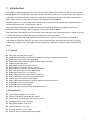
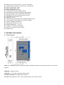
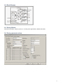
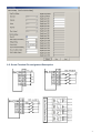
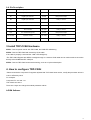
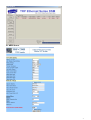
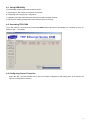
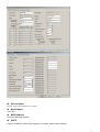
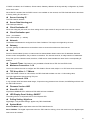
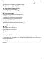
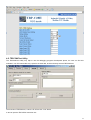
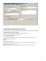
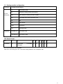
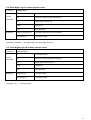
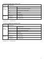
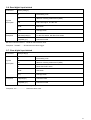
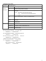
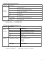
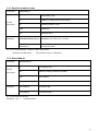
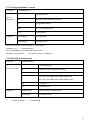
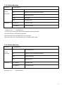
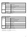
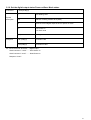
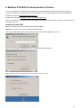
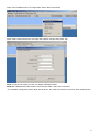
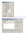
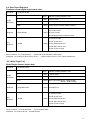
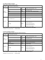
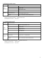
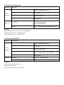
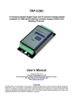
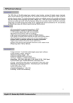
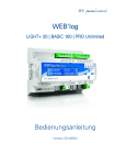
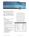
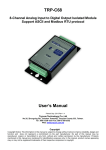
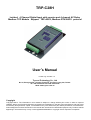
TRP-C28H Isolated 4 Channel Digital Input with counter and 4 channel AC Relay Modbus TCP Module Support TRP-ASCII, Modbus RTU/ASCII protocol User’s Manual Printed Aug. 2013 Rev 1.0 Trycom Technology Co., Ltd No.35, Zhongxing Rd., Guishan Township, Taoyuan County 333, Taiwan. Tel : 886-3-350-3351 Fax: 886-3-350-3352 Web: www.trycom.com.tw Copyright Copyright Notice: The information in this manual is subject to change without prior notice in order to improve reliability, design and function and dosed not represent a commitment on the part of the manufacturer. No part of this manual may be reproduced, copied, or transmitted in any form without the prior written permission of manufacturer. Acknowledgment Products mentioned in this manual are mentioned for identification purpose only. Products manes appearing in this manual may or may not be registered trademarks or copyright of their respective companies. 1. Introduction TRP-C28H an Isolated Digital Input with counter and AC Relay Modbus TCP Module, provides 4 channels optical isolated digital input channels and counter and 4 Channel AC Relay that allow you to input the logic signal from +/- 0 to 30V DC and 5A /250V AC relay on network, it supports 3 communication Protocol, TRP-ASCII, Modbus RTU / ASCII, TRP-C28H can be easy and convenient to use application supports Modbus. Software engineers can use the TRP-ASCII or Modbus RTU command set quickly and easily integrated into the self-development program, such as Microsoft VB, VC... TRP-C28H built-in independent IP, WEB-browsing more convenient to rewrite the configuration and collect information through computers, tablet computers, smart phones, will be available! TRP-C28H built-in watchdog function to ensure the normal operation of the module, and a built-in voltage monitoring to ensure that the boot, excellent and advanced hardware for harsh environment. TRP-C28H with another TRP-C28H remote control directly, do not need to run the software and equipment. TRP-C28H also offers the maximum connection 16 host client to link the network server that is easy to operate in Modscan32 ,Modbus Poll, CAS Modbus Scanner and SCADA ...application uses TCP mode and Virtual-COM mode. 1-1 .Features Wide input range DC power supply. Automatically determine 3 TRP-ASCII and Modbus RTU/ASCII communication protocol. 16 TCP Port can be open at the same time. Heart Beat function ensures a reliable communicating connection. Support Virtual-COM mode. WEB PAGE can be directly read IO status. Easily update the firmware using the Internet. Back to factory configuration by external touch Button. Auto reconnection when power or Ethernet fail. Digital input signal from +/- 0 to 30V DC. Built-in surge absorbers in each relay N.C and N.O. Built-In watchdog function prevents system boot fail. LED for each I/O channels working status. Support Auto-MDIX twisted pair crossover detection and Auto-Correction. Power/Link/8 CH D I/O LED indicator. DIN-Rail and panel mount support. Dual power input select from screw terminal or DC-Jack.. 1-2 .Specification Power Input Voltage DC +10V to +30V. Protocol: TRP-ASCII and Modbus RTU/ASCII. Input channel: 16 digital input channels with counter. Input digital input counter: 0~65535. Input optical isolation: 3750 Vrms. Input logical level 0 +1V (max). Input logical level 1 +4.0V ~ +30V. Output channel: 4 channel power reply outputs. 2 Relay type: 2 Form A (RL1,RL2) , 2 Form C (RL3,RL4). Contact ratting: 5A /30V DC , 5A /120V AC , 5A /250V AC. Relay surge strength: 4000V. Relay operating time: 3mS. Relay operating life: 2 X 10(7). Communication interface: Ethernet RJ45. Configuration mode: Device Manager, WEB settings. Matching remote control: with another TRP-C28H. Heart Beat: TCP Port sent string every 5 seconds. TCP Maximum Connection:1~16. Module ID :1~255. Connection type: Screw terminal for maximum AWG 12 wire. Power supply: Screw terminal, or external DC adapter. Power consumption 320mA/12V. Operating environment: 0 to 50℃. Storage temperature:. -10 to 70℃. Humidity: 10~90% Non-condensing. Dimension: 151mm X 75mm X 26mm . Weight: 395g. 2. Hardware Description 2-1. Panel layout Notice: The Module provides two type power inputs, optional DC-JACK or Screw Terminal input, not to two used together! PWR LED: Blinking is ready. LINK LED: RJ-45 cable connection and data active. D0~D3/R1~R4 LED: Each digital status indication. DC Jack: Power Input DC +10V to +30V, Please use the 5.5*2.1mm DC JACK. 3 2-2. Block Diagram 2-3. Factory Button Hold down the button, and then power on, until the power light flashes, Release the button. 2-4. Factory parameter values 4 2-5. Screw Terminal Pin assignment Description 5 2-6. Pin Description DI3 Digital input Channel 3 R4-COM Relay 4 common DI2 Digital input Channel 2 R4-NC Relay4 Normal Close DI1 Digital input Channel 1 R4-NO Relay4 Normal Open DI0 Digital input Channel 0 R3-COM Relay 3 common IN-COM The isolated side power input MAX.30V R3-NC Relay3 Normal Close N.C Not connected R3-NO Relay3 Normal Open N.C Not connected R2-COM Relay 2 common N.C The isolated side ground R2-NO Relay2 Normal Open DC 10~30V Input DC 10~30V R1-COM Relay 1 common GND Power Ground R1-NO Relay1 Normal Open 3.Install TRP-C28H Hardware STEP1: Connect power source with TRP-C28H, the PWR LED will blinking. STEP2: Connect TRP-C28H with network by RJ45 cable. If the cable is properly connected the “LINK” LED will light up. *The TRP-C28H Support Auto-MDIX, A straight-through or crossover RJ45 cable can be used to make a connection directly to the HUB/Router/PC LAN port. STEP3: Connect TRP-C28H screw terminal wiring, such as 2-5 picture description. 4. How to configure TRP-C28H *Please note that the computer's IP segment adjusted with TRP-C28H same section, modify the parameter values in order to effectively store! For example: Computer IP is 192.168.1.xx TRP-C28H 192.168.1.1 There are 2 ways can change the module parameter values. A.DSM Software 6 B. WEB Server 7 4-1. Using DSM Utility The DSM utility software performs several functions: A: Searching for TRP-C28H connected to the network. B: Displaying and changing the configuration. C: Upgrading the TRP-C28H firmware, Refer the Firmware upgrade help file. D: Saving and Loading Configuration from external log File or memory. 4-2. Searching TRP-C28H Once TRP-C28H is connected to the network the DSM software will search it and display it in a window by name, IP address, Mac….Information. 4-3.Configuring Server Properties Select the “NO.” item and Double click to open the module configuration, after setting then click “Submit” will save the configuration to memory. 8 Device Name: Device server name, Maximum 10 chars. Model Name: TRP-C28H. MAC Address The TRP-C28H MAC address. DHCP If DHCP is disabled, it allows user setting the IP address, Subnet mask, Gateway. 9 If DHCP is enabled, the IP address, Subnet mask, Gateway address will be dynamically configuration by DHCP server such router. When DHCP is enabled, but the DHCP server is not available on the network, the TRP-C28H will timeout then back to factory setting IP=192.168.1.1. Server Listening IP The TRP-C28H IP address. Server Data listening port TRP-C28H port address. Client Destination IP When user using the pair mode, the client setting need to input module IP and port which one need to connect. Client Destination port Client port address. Port: 16 bit number. (1 ~ 65535) Netmask The default LAN Netmask is configured for a Class C address. This maybe reconfigured by the user. Gateway Input the gateway IP address that can be allows users to access the serial server from internet. DNS Short for Domain Name System, an Internet service that translates domain names into IP addresses. Because domain names are alphabetic, they're easier to remember. The Internet however, is really based on IP addresses. Every time you use a domain name, therefore, a DNS service must translate the name into the corresponding IP address. Transmit Timer: This feature is only available to Serial Server TRP-C37 and TRP-C37M. Maximum Connection: 1~16 The function allows the user to configure the TRP-C28H in Server mode, adjust 1~16 TCP client host connections. TCP Keep Alive: 1~7 /Minute When TRP-C28H in Server or Client mode, the TRP-C28H without data over the 1~7 Min setting value, The TRP-C28H will be disconnecting TCP port. New Password: 1234 It only accepts value from1000~9999 integer, if input the wrong password over 5 times, the WEB-Page will lock until the TRP-C28H re-boot. Firmware Version: ABC Slave ID:1~255. ID performs MODBUS RTU / ASCII and TRP-ASCII will use to address. LED Display Panel Setting :ON/OFF The setting will turn on all panels LED or Turn off panel LED. Polling Setting: High/Low. Digital High / Low potential settings, Applies only TRP-C26H/C28H System Mode Power ON Mode: Digital output state when the TRP-C28H Power On. Save ON Mode: The digital output state when the TRP-C28H is working, Once this mode is set, the digital output state cannot be rewritten. 10 Pair Mode: It can be used as a remote manual remote control, when the TRP-C24H 16 DO 和 TRP-C26H 16 CH DI, TRP-C28H 4 D I/O with TRP-C28H 4 D I / O. Without any driver. Trycom Checksum setting: Disable/Enable. TRP-ASCII command used bit checksum. Power On Mode Output: 0000~FFFF. Digital output state when TRP-C28H Boot! Save ON Mode Output:0000~FFFF. Digital output state when watchdog enable! Digital Output Status Display last stored in the memory of the digital output state. Digital Input Status This feature is only available to TRP-C26H and TRP-C28H, Display last stored in the memory of the digital input state. Digital Input CH1~CH16 Display last stored in the memory of the digital input counter value. This feature is only available to TRP-C26H and TRP-C28H. Submit Save the setting value to memory. Save Save the setting value to external log file. Load Load the setting value to external log file. Upgrade Upgrade the TRP-C28H firmware. 4-4.Using the WEB Server mode The Web Server can be used to configure the TRP-C28H from any web browser software (such as I.E). In Internet Explorer type the IP Address of the TRP-C28H into the address field and press the Enter key. The following window will appear: Example: If TRP-C28H’s IP is 192.168.1.1 ,Please Input the 192.168.1.1 then enters at web address, the web-page will appear. 11 4-5. TRPCOM Test Utility The TRPCOM test utility may help to use the debugging program development phase, the user can find this software in our CD internal directory copied to the hard disk, and then directly execute TRPCOM.exe. The execution TRPCOM.exe, enter the IP & Port click "Link" button It can be input the TRP-ASCII instruction set. 12 5. TRP-ASCII Communication Protocol TRP-C28H supports three modes of communication Protocol TRP-ASCII, Modbus RTU, Modbus ASCII. TRP-ASCII Command Protocol Description Command Format :”Leading Code”+”ID Address”+”Command”+”CHK”+(cr) . at :”Leading Code”+”ID Address”+”Data”+”CHK”+(cr) . How to calculate the checksum 1. Calculate all characters of the command string to get the ASCII sum, except the character return. 2. Mask the sum of string with 0FFH. Example: Send the command is “$06M”. Sum of string is “$”+”0”+”6”+”M”=“24H”+”30H”+” 4D“=“A1H”……The checksum and [CHK]=“A1”. Response string with checksum is :” A1“. TRP-ASCII: ease of use TRP-ASCII integration to develop their own software, such as VB, VC . 13 Command List Function Description Paragraph index %IDNNPP00DD(CHK)(cr) Setting module configuration See 5-1 #IDN (CHK)(cr) Read digital input channel counter value See 5-2 #IDCN(CHK)(cr) Clear digital input N channel counter value See 5-3 #IDCW(CHK)(cr) Clear all digital input counters value See 5-4 #IDCS(CHK)(cr) Save all digital input counters value See 5-5 $IDLS(CHK)(cr) Read digital input latched See 5-6 $IDC(CHK)(cr) Clear digital input latched See 5-7 #IDPPDD (CHK)(cr) Digital Output Data See 5-8 $ID6 (CHK)(cr) Read digital input/output status See 5-9 $IDF (CHK)(cr) Read the module’s firmware version See 5-10 $IDM (CHK)(cr) Read the module’s name See 5-11 $01RS(CHK)(cr) Reset Module See 5-12 ~IDONN (CHK)(cr) Change the module’s name See 5-13 ~IDLEDA(CHK)(cr) Set the module’s LED operating mode See 5-14 ~IDWE (CHK)(cr) Enable watchdog See 5-15 ~IDWD (CHK)(cr) Disable watchdog See 5-16 ~IDWR (CHK)(cr) Read watchdog status See 5-17 ~ID4V (CHK)(cr) Read power on/Safe on mode See 5-18 ~ID5V (CHK)(cr) Set the digital output status Power on/Save Mode status See 5-19 14 5-1. Setting module configuration Command %IDNNPP00DD(CHK)(cr) % First leading code ID Address of setting module 00-FF(HEX) NN New address of setting from 00-FF(HEX) PP The Digital I/O module type define to 40 00 00 DD Data format CHK Checksum (cr) Carriage return !ID(CHK) (cr) Command valid ?ID (CHK)(cr) Command Invalid Syntax Description Response DD: Data Format Bit 7 6 Function 0 Checksum 0:Disable 5 4 3 2 1 0 0 0 0 0 0 0 1:Enable EX: Send command:”%0103400000”. New ID is “03”,D I/O type is “40” ,Checksum setting disable is “00”, Response:”!01”. 15 5-2. Read digital input channel counter value Command Syntax #IDN(CHK)(cr) # First leading code ID Address of setting module 00-FF(HEX) N Digital Input channel 0~3 CHK Checksum (cr) Carriage return !IDCCCCC(CHK) (cr) Command valid CCCCC from 0~65535 ?ID (CHK)(cr) Command Invalid description Response Ex:Send command:”#012” Read the TRP-C26H channel 2 counter value Response: ”!0100023”…..The digital input have been trigger 23 times. 5-3. Clear digital input N channel counter value Command Syntax #IDCN(CHK)(cr) # First leading code ID Address of setting module 00-FF(HEX) CN Digital Input channel N=0~F CHK Checksum (cr) Carriage return !ID(CHK) (cr) Command valid ?ID (CHK)(cr) Command Invalid description Response Ex:Send command:”#01C0”…Clear channel 0 counter value. Response: ”!01”…... Command valid. 16 5-4. Clear all digital input counters value Command Syntax #IDCW(CHK)(cr) # First leading code ID Address of setting module 00-FF(HEX) CW Clear all channels counter values CHK Checksum (cr) Carriage return !ID(CHK) (cr) Command valid ?ID (CHK)(cr) Command Invalid description Response Ex:Send command:”#01CW”…Clear all channels counter value. Response: ”!01”…... Command valid 5-5. Save all digital input counters value Command Syntax #IDCS(CHK)(cr) # First leading code ID Address of setting module 00-FF(HEX) CS save all channels counter values CHK Checksum (cr) Carriage return !ID(CHK) (cr) Command valid ?ID (CHK)(cr) Command Invalid description Response Ex:Send command:”#01CS”…Clear all channels counter value. Response: ”!01”…... Command valid 17 5-6. Read digital input latched Command $IDLS(CHK)(cr) $ First leading code ID Address of setting module 00-FF(HEX) LS S=0 Latch logic 0, S=1 No use. CHK Checksum (cr) Carriage return !IDLLHH(CHK)(cr) LL=DI0~DI7 status, HH=DI8~DI15 status. ?ID(CHK) (cr) Command Invalid Syntax description Response Ex:Send command:”#01L0”…Read all channels latch value. Response: ”!01000F”…... All channels have been trigger. 5-7. Clear digital input latched Command Syntax $IDC(CHK)(cr) $ First leading code ID Address of setting module 00-FF(HEX) C Clear CH0~CHF Lactch. CHK Checksum (cr) Carriage return !ID(CHK)(cr) Command vaild ?ID(CHK) (cr) Command Invalid description Response Send command:”$01C”…….Clear digital input latch . Response:”!01 ”…………… Latch have been clear. 18 5-8.Digital Output Data Command Syntax #IDPPDD(CHK)(cr) # First leading code ID Address of setting module 00-FF(HEX) PP D I/O type description :0A/ 00 DO0~DO3 low byte data (Multi-Channel) :1L/ AL: DO0~DO3 low byte data (Single-Channel) L=0~3 Response DD DD:00~FF (Milti-Channel) CHK Checksum (cr) Carriage return >(CHK)(cr) Command valid !ID(CHK) (cr) ?ID (CHK)(cr) DD:00 or 01 (Single-Channel) Parameter invalid (*Command data error!) Command Invalid *Multi-Channel mode (Output control for one BYTE) EX: Send command :”#010A02”…..CH 1 Relay 1 ON. Response:”>”……. Command valid. EX: Send command:”#01000A”…...CH1 nad CH3 Relay ON. Response:”>”……. Command valid. EX: Send command:”#01000G”…Data=“0G”…….Data error!. Response:”?0”…….Parameter error! . *Single-Channel mode( Output control for one BIT) EX: Send command:”#011001”….. CH0 Relay ON. Response:”>”……. Command valid. Send command:”#011201”….. CH2 Relay ON. Response:”>”……. Command valid. 19 5-9.Read digital input/output status Command $ID6(CHK)(cr) $ First leading code ID Address of setting module 00-FF(HEX) 6 Read digital output status CHK Checksum (cr) Carriage return !ID0L0H(CHK)(cr) L=DO0~DO3 status, H=DI0~DI3 status. ?ID(CHK) (cr) Command Invalid Syntax description Response EX: Send command:$016…….Read digital output status . Response:”!010308”…….DO1,DO2,DI3...Enable. 5-10. Read the module’s firmware version Command Syntax $IDF(CHK)(cr) $ First leading code ID Address of setting module 00-FF(HEX) F Command for reading module’s version CHK Checksum (cr) Carriage return !IDMODDDMMYY(CHK)(cr) MOD :The module’s model description Response DD: Date MM: Month YY : Year ?ID(CHK)(cr) Command Invalid EX: Send command:$01F…Read the TRP-C28H’s version. Response:”!01C24H090113”……. The TRP-C28H’s version date is “01/09/2013”. 20 5-11. Read the module’s name Command $IDM(CHK)(cr) $ First leading code ID Address of setting module 00-FF(HEX) M Reading module’s name CHK Checksum (cr) Carriage return !IDNNNNNNNNN(CHK)(cr) NNNNNN :The chars from 1~9 chars ?ID(CHK)(cr) Command Invalid Syntax description Response EX: Send command:$01M…Read the TRP-C28H’s name. Response:”!01TRPC24H”……. The module’s name is “TRPC24H”. 5-12. Reset Module Command $IDRS(CHK)(cr) $ First leading code ID Address of setting module 00-FF(HEX) RS Reset Module (cr) Carriage return !ID (CHK)(cr) Command valid ?ID(CHK)(cr) Command Invalid Syntax description Response EX: Send Command:”$01RS” Response:” !01”……. . Command valid! 21 5-13. Change the Module ‘s name Command ~IDONN(CHK)(cr) ~ First leading code ID Address of setting module 00-FF(HEX) O Change Module Name NN NN : 1~9 characters char (cr) Carriage return !ID (CHK)(cr) Command valid ?ID(CHK)(cr) Command Invalid Syntax description Response EX: Send Command:”~01O123456789”…Change Name. Response:” !01”……. . Command valid! Send command:$01M…Read the TRP-C28H’s name. Response:”!01123456789”……. The module’s name is “TRPC24H”. 5-14. Set LED operating mode Command Syntax description ~IDLEDA(CHK)(cr) ~ First leading code ID Address of setting module 00-FF(HEX) LED Set the module’s LED operating mode A A=1 Turn off all LEDS, when Output Enable= ON. A=0 Turn on all LEDS, when Output Enable= OFF. Response CHK Checksum (cr) Carriage return !IDNN(CHK)(cr) NN=ON or OFF Command valid ?ID(CHK)(cr) Command Invalid EX: Send command:”~01LED1”….. Turn off all LED, when Channel Enable ON. Response:”!01OFF”……. . Command valid. 22 5-15. Enable Watchdog Command Syntax ~IDWE(CHK)(cr) ~ First leading code ID Address of setting module 00-FF(HEX) WE Watchdog function CHK Checksum (cr) Carriage return !ID(CHK)(cr) Command valid ?ID(CHK)(cr) Command Invalid description Response EX: Send Command:”~01WE”……….Enable Watchdog . .. Response:” !01”……. Command valid. *The user can not change the digital output state when watchdog enable, this mode will keep until the watchdog disable. When the watchdog enable digital output into safe mode. There are 3 ways you can set the safe mode, command / WEB / DSM. 5-16. Disable Watchdog Command ~IDWD(CHK)(cr) ~ First leading code ID Address of setting module 00-FF(HEX) WD Disable Watchdog (cr) Carriage return !ID (CHK)(cr) Command valid ?ID(CHK)(cr) Command Invalid Syntax description Response EX: Send Command:”~01WD”…Watchdog Disable. Response:” !01”……. . Command valid! 23 5-17. Read Watchdog State Command ~IDWR(CHK)(cr) ~ First leading code ID Address of setting module 00-FF(HEX) WR Read Watchdog State (cr) Carriage return !IDWN (CHK)(cr) N=E Enable Syntax description Response N=D Disable ?ID(CHK)(cr) Command Invalid EX: Send Command:”~01WR”…Read Watchdog state. Response:” !01WE”……. . Watchdog Enable. 5-18. Read Power on/Safe Mode Command Syntax ~ID4V(CHK)(cr) ~ First leading code ID Address of setting module 00-FF(HEX) 4 Read power on/safe mode status V V=P: Power on description V=S: Safe mode Response CHK Checksum (cr) Carriage return !ID0L (CHK)(cr) L:DO7~DO0 ?ID(CHK)(cr) Command Invalid EX: Send Command:~014P……….Read Power on output status. Response:” !0107”……. . Command valid. EX: Send Command:~014S……….Read save mode output status. Response:” !0108”……. . Command valid. 24 5-19. Set the digital output status Power on/Save Mode status Command ~ID5V(CHK)(cr) ~ First leading code ID Address of setting module 00-FF(HEX) 5 Save the current digital output is save or power on mode V V=P Power on Syntax description V=S Safe mode Response (cr) Carriage return !ID (CHK)(cr) Command valid ?ID(CHK)(cr) Command Invalid EX: Send Command:”#010A07”… Digital output Send Command: “~015P”…….Save Power on. Send Command:”~014P” …….Read Power on Response:”!0107”. 25 6. Modbus RTU/ASCII Communication Protocol * For more modbus RTU / ASCII protocol specification, please download from http://www.modbus.org website. Obtain more modbus TCP instruction test, we recommend user can be downloaded from the following Web site Modbus Poll Test utility http://www.modbustools.com/ Modbusscan Test utility http://www.win-tech.com/html/modbus1.htm. User can use the virtual-com program with TRPCOM.exe for Modbus RTU test; these programs can be found in our directory of the CD! Install the Virtual-COM Step 1. Insert the TRP-Serial CD and find the TRP-C28H folder. Step 2.Click “Vcomm.exe” icon then install Virtual-COM utility. *The Virtual COM utility support multi-language, please select which language do you need. Step3. Click “OK” button and select “VSP run as Client support Server Device”. Step4. Select “Create virtual serial by device scanner”, then press “OK” 26 Step5. Run VCOMM.exe then click right button select “New Virtual COM” Step6. Select “Select Serial Port” and input TRP-C28H IP and port then press “OK”. Step7. If Virtual-Com setting success, the display will appear bellow. Step8.Run TRPCOM utility then select virtual-com port make a TRP-C28H command. *If in VCOMM‘s configuration select “Boot with windows”, the virtual-com will Auto-connection when windows start. 27 * TRP-C28H in use the Virtual com mode, the default data format is 9600, N, 8,1, this mode is not allowed to change. 28 Modbus TCP Command List Command List Function Description C28H Description Index ID 01 00 SS 00 NN Read Coils Read relay output readback value 6-1 ID 02 00 SS 00 NN Read Discrete Inputs Read the current digital input value 6-2 ID 03 00 SS 00 NN Read Holding Registers Read the current relay output readback count value 6-3 ID 04 00 SS 00 NN Read Input Registers Read the current digital input count value 6-4 ID 05 00 SS DD 00 Write Single Coil Write Single channel output data 6-5 ID 0F 00 SS 00 NN BC 0L Write Coils Write multi channel output data 6-6 ID 06 00 SS DD DD Write single register Write single channel counter value 6-7 ID 10 00 SS 00 CN BC DD DD .. Write multiple registers Write multi channel counter value 6-8 ID 10 00 00 00 01 Save multiple registers Save multi channel counter value to memory 6-9 Additional modbus RTU command set Command List Function Description Index ID 46 00 00 Read the module’s name 6-10 ID 46 04 IP 00 00 00 Setting module new ID 6-11 ID 46 07 00 Read the module’s Firmware 6-12 ID 46 0B WS 00 Enable/Disable watchdog. 6-13 ID 46 0C 00 Read watchdog status 6-14 ID 46 0D 0S 00 Set up LED ON/OFF 6-15 6-1. Read Coils Read relay output readback value Command Syntax Description ID 01 00 SS 00 NN ID 1Byte Address of setting module 1~247 01 1 Byte Function Code 00 SS 2 Bytes Start channel number, 0x0000~0x0004 00 NN 2 Bytes Output channel number,0x0001~0x0004 ID=1~247 01:Function Code Response ID 01 BC 0L 4 Bytes BC: Byte counter 0L : Relay output read back value ID=1~247 81 :Function Code Error Response ER=00 Syntax error ID 81 ER 3 Bytes ER=01 Data Format error ER=02 Start channel error ER=03 I/O out of range Example:Send command :” 01 01 00 00 00 04”…..Read RL1~RL4 relay Output read back value. Response:” 01 01 01 08”….. RL4 Enable. 29 6-2. Read Discrete Inputs Read the current digital input value Command Syntax Description ID 02 00 00 00 NN ID 1Byte Address of setting module 1~247 02 1 Byte Function Code 00 SS 2 Bytes Start channel number, 0x0000 00 NN 2 Bytes Input channel number,0x0001~0x0004 ID=1~247 02:Function Code Response ID 02 BC LL 4 Bytes BC: Byte counter LL : Digital current input value ID=1~247 81 :Function Code Error Response ER=00 Syntax error ID 82 ER 3 Bytes ER=01 Data Format error ER=02 Start channel error ER=03 I/O out of range Example: Send command :” 01 02 00 00 00 04”…..Read DI0~DI3 Digital Input readback value. Response:” 01 02 01 08 ”….. DI3=Enable. 6-3. Read Holding Registers Read the current relay output readback count value Command Syntax Description ID 03 00 SS 00 NN ID 1Byte Address of setting module 1~247 03 1 Byte Function Code 00 SS 2 Bytes Start channel number, 0x0000~0x0004 00 NN 2 Bytes Output channel number,0x0001~0x0004 ID=1~247 03:Function Code Response ID 03 BC NN NN 5 Bytes BC: Byte counter NN NN: Digital output read back value ID=1~247 83 :Function Code Error Response ER=00 Syntax error ID 83 ER 3 Bytes ER=01 Data Format error ER=02 Start channel error ER=03 I/O out of range Example: Send command :” 01 03 00 00 00 04 ”…..Read digital RL11~RL4 readback counter value. Response:” 01 03 08 00 03 00 12 00 37 00 12 ”. 30 6-4. Read Input Registers Read the current digital input count value Command Syntax Description ID 04 00 SS 00 NN ID 1Byte Address of setting module 1~247 04 1 Byte Function Code 00 SS 2 Bytes Start channel number, 0x0000~0x0004 00 NN 2 Bytes Output channel number,0x0001~0x0004 ID=1~247 04:Function Code Response ID 0 BC NN NN 5 Bytes BC: Byte counter NN NN: Digital output read back value ID=1~247 84 :Function Code Error Response ER=00 Syntax error ID 84 ER 3 Bytes ER=01 Data Format error ER=02 Start channel error ER=03 I/O out of range Example: Send command :” 01 04 00 00 00 04 ”…..Read CH0~CH3 read back counter value. Response:” 01 04 08 00 01 00 01 03 FC 00 1E ”….. Bytes Counter=8,DI0 =1, DI1=1,DI2=1020,DI3=30. .6-5. Write Single Coil Write Single channel output data Command Syntax Description Response ID 05 00 SS DD 00 ID 1Byte Address of setting module 1~247 05 1 Byte Function Code 00 SS 2 Bytes Start channel number, 0x0000~0x0003 DD 00 2 Bytes ID 05 00 SS DD 00 5 Bytes Command Line Write output data DD=FF.. Relay Enable DD=00 Relay Disable ID=1~247 85 :Function Code Error Response ER=00 Syntax error ID 85 ER 3 Bytes ER=01 Data Format error ER=02 Start channel error ER=03 I/O out of range Example: Send command :” 01 05 00 03 FF 00 ”…..RLY4 Output Enable. Response:” 01 05 00 03 FF 00“…Command Valid. 31 6-6. Write Coils Write multi channel output data Command Syntax Description Response ID 0F 00 SS 00 NN BC 0L ID 1Byte Address of setting module 1~247 0F 1 Byte Function Code 00 SS 2 Bytes Start channel number, 0x0000~0x0003 00 NN 2 Bytes Output channel number=0x0001~0x0004 BC 1 Bytes Byte counter 0L 1 Bytes Write output data L=0~F ID 0F 00 SS 00 NN 6 Bytes Command Line ID=1~247 8F :Function Code Error Response ER=00 Syntax error ID 8F ER 3 Bytes ER=01 Data Format error ER=02 Start channel error ER=03 I/O out of range Example: Send command:”01 0F 00 00 00 04 01 0B”…RL1,RL2,RL4 Enable. Response:”01 0F 00 00 00 04”…Command Valid. 6-7. Write single register Write single channel counter value Command Syntax Description ID 06 00 SS DD DD ID 1Byte Address of setting module 1~247 06 1 Byte Function Code 00 SS 2 Bytes Start channel number, 0x0000~0x0003 DD DD 2 Bytes Write Counter Vaile DDDD=0x0000~0xFFFF ID 06 00 SS DD DD 6 Bytes Command Line Response ID 86 :Function Code ER=00 Syntax error ID 86 ER (CRC) 4 Bytes ER=01 Data Format error ER=02 Start channel error ER=03 I/O out of range Example:Send command :” 01 06 00 03 00 63 ”…..Write DI3 Counter Value=99. Response:”01 06 00 03 00 63 ”….. Command Valid. 32 6-8. Write multiple registers Write multi channel counter value Command Syntax ID 10 00 SS 00 CN BC DD DD .. ID 1Byte Address of setting module 1~247 10 1Byte 10=Function Code 00 SS 2 Bytes Start channel number, 0x0000~0x0003 00 CN 2 Bytes Counter Number =0x0001~0x0004 BC 1 Byte Byte Counter DD DD……. 2~8 Bytes Counter Vaile DDDD=0000~FFFF ID 10 00 SS 00 CN 6 Bytes Command Line Description Response ID 90 :Function Code ER=00 Syntax error ID 90 ER ER=01 Data Format error 3 Bytes ER=02 Start channel error ER=03 I/O out of range Send command:” 01 10 00 00 00 04 08 00 0A 00 14 00 1E 00 28 ”… Write DI0~DI3 Counter Value. Response:”01 10 00 00 00 04”….. Command Valid. 6-9.Save multiple registers Save current multi channel counter value to memory Command ID 10 00 00 00 01 02 00 00 ID 1Byte Address of setting module 1~247 Syntax 10 1 Byte 10=Function Code Description 00 00 2 Bytes Start channel number, 0x0000 00 01 2 Bytes Counter Number =0x0001 02 00 00 3 Bytes Save all counters to memory ID 10 00 00 00 01 6 Bytes Command valid ID 90 :Function Code Response ER=00 Syntax error ID 90 ER 3 Bytes ER=01 Data Format error ER=02 Start channel error ER=03 I/O out of range Send command:” 01 10 00 00 01 02 00 00”… Save all current counters Value to memory. Response:”01 10 00 00 00 01”….. Command Valid. 33 6-10.Read the module’s name Command ID 46 00 00 ID Address of setting module 1~247 Syntax 46 Function code Description 00 Read module’s name 00 Reserved code ID 46 00 00 ….Module command Line Response ID 46 00 00 0C 28 00 ID C6 00 0C 28 :Module’s Name is C28 ID C6 C6:Function Code 00: Reserved code EX: Send Command:”01 46 00 00”…….Read the TRP-C28’s name. Response:”01 46 00 00 0C 28 00 “……Module’s name is C28. Error Response: “01 C6 00”……Error code. 6-11. Setting module new ID Command ID 46 04 IP 00 00 00 ID Address of setting module 1~247 46 Function Code 04 Setting module ID IP New module’s ID 00 00 00 Reserved code ID 46 04 00 00 ID 46 04 00 00 ….Command valid ID C6 00 ID C6 Syntax Description Response C6:Function Code 00: Reserved code EX: Send Command:”01 46 04 08 00 00 00”…….Set up the new ID is “03”. Response:”01 46 04 00 00 “……New ID is 08. Error Response: “01 C6 00”……Error code. 34 6-12.Read the module’s Firmware Command Syntax Description ID 46 07 00 ID Address of setting module 1~247 46 Function Code 07 Read module’s Firmware 00 Reserved code ID 46 07 YY MM DD 00 ID 46 07 ……Module command Line YY:Year MM :Month DD:Date 00 : Reserved code Response ID C6 00 ID C6 C6:Function Code 00: Reserved code Example: Send Command:”01 46 07 00”…….Read Firmware Version. Response:”01 46 07 13 02 28 00“…Firmware Version 02/28/2013. Error Response: “01 C6 00”……Error code. 6-13.Enable/Disable watchdog Command ID 46 0B WS 00 ID Address of setting module 1~247 46 Function Code 0B Setting Watchdog Status Syntax Description WS Response WS=00 Watchdog Disable WS=01 Watchdog Enable 00 Reserved code ID 46 0B 00 00 ID 46 0B 00 ……Command valid ID C6 00 ID C6 C6:Function Code 00: Reserved code Example: Send Command:”01 46 0B 01 00”…….Watchdog Enable. Response:”01 46 0B 00“…Command valid. Error Response: “01 C6 00”……Error code. 35 6-14.Read watchdog status Command Syntax Description ID 46 0C 00 ID Address of setting module 1~247 46 Function Code 0C Read watchdog status 00 Reserved code ID 46 0C ……Module command line Response ID 46 0C WT WT=01 Watchdog enable WT=00 Watchdog Disable ID C6 00 ID C6 C6:Function Code 00: Reserved code Example: Send Command:”01 46 0C 00”…Read watchdog status. Response:”01 46 0C 01 ….Watchdog enable. Error Response: “01 C6 00”…Error code. 6-15.Set up LED ON/OFF Command ID 46 0D 0S 00 ID Address of setting module 1~247 46 Function Code 0D Set Up LED Status Value Syntax Description 0S Response S=0 Turn on all LED when DIO enable off S=1 Turn off all LED when DIO enable on 00 Reserved code ID 46 0D 00 ID 46 0D ……Command valid ID C6 00 ID C6 C6:Function Code 00: Reserved code Example: Send Command:”01 46 0D 01 00. Response:”01 46 0D 00. Error Response: “01 C6 00”…Error code. 36 7. Pair Mode TRP-C28H support pairing mode with the TRP-C28H, Applied to 4 digital channels input and 4 AC relay output with over the network, without any driver with computer hardware. All digital LED flashes in pairing mode until successfully paired will stop blinking; TRP-C28H sustained in connection automatically, regardless of any party the power to re-open or network disconnection to ensure normal transmission. product application are as follows: 37 7-1 Parameter setting example Perform DSM utility to change the parameters TRP-C28H server parameter setting 38 TRP-C28H Client parameter setting 39 8. Application 40