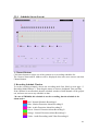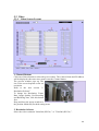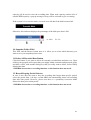
1
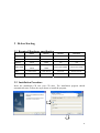
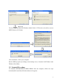
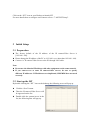
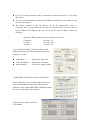
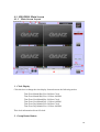
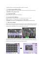
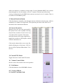
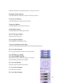
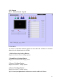
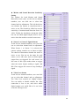
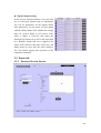
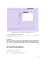
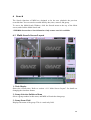
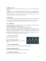
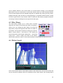
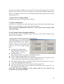
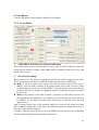
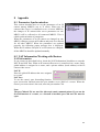
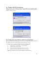
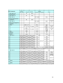
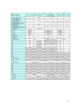
MRS32/18/8/SMS4096
User’s Manual
For Version 1.0.0.1
1
2
3
4
Introduction ............................................................................................................................ 3
1.1
Overview..................................................................................................................... 3
1.2
Example of System Composition ............................................................................... 4
1.3
Warnings and Disclaimer ........................................................................................... 5
Before Starting....................................................................................................................... 6
2.1
Required Hardware specification ............................................................................... 6
2.2
Installation Procedure................................................................................................. 6
2.3
Uninstall Procedure .................................................................................................... 7
2.4
Configuring MRS with IST/MST ................................................................................. 8
Initial Setup ............................................................................................................................ 9
3.1
Preparation ................................................................................................................. 9
3.2
Start up the IST .......................................................................................................... 9
3.3
IST Screen................................................................................................................ 10
3.4
SMS/MRS initial setup ............................................................................................ 12
3.5
MST Screen.............................................................................................................. 14
Starting SMS/MRS.............................................................................................................. 15
4.1
SMS/MRS Main Screen.......................................................................................... 16
4.1.1
5
Main Screen Layout ...................................................................................... 16
4.2
Control Mode ........................................................................................................... 20
4.3
PTZ Mode ................................................................................................................ 21
4.4
PTZ Preset Mode.................................................................................................... 22
Setup.................................................................................................................................... 23
5.1
Channel .................................................................................................................... 23
5.1.1
5.2
Schedule................................................................................................................... 26
5.2.1
5.3
Schedule Screen Layout............................................................................... 27
Video ........................................................................................................................ 29
5.3.1
5.4
Channel Screen Layout ................................................................................ 24
Video Screen Layout..................................................................................... 29
Alarm ........................................................................................................................ 32
1
5.4.1
5.5
6
7
Password.................................................................................................................. 35
5.5.1
Password Screen Layout .............................................................................. 35
5.5.2
Adding and Removing Users ........................................................................ 38
5.5.3
Changing ID and/or Password Button .......................................................... 38
5.5.4
DVR System Mode ....................................................................................... 38
Search.................................................................................................................................. 39
6.1
Multi-Search Screen Layout ..................................................................................... 39
6.2
Playback ................................................................................................................... 42
6.3
Control Menu ............................................................................................................ 43
6.4
Tool Menu................................................................................................................. 43
6.5
Filter Menus.............................................................................................................. 45
6.6
Motion Search .......................................................................................................... 45
6.7
Remote Search ........................................................................................................ 47
MST/IST Setup .................................................................................................................... 48
7.1
Connect to Camera .................................................................................................. 48
7.2
MST/IST Setup Screen............................................................................................ 49
7.3
8
Alarm Screen Layout .................................................................................... 32
7.2.1
MST/IST Setup Screen Layout ..................................................................... 49
7.2.2
Event Mode ................................................................................................... 51
7.2.3
In PTZ Mode ................................................................................................. 52
In Firmware Mode .................................................................................................... 53
Appendix.............................................................................................................................. 54
8.1
Parameter Synchronization ...................................................................................... 54
8.2
NAT Information/Working with Routers.................................................................... 54
8.3
Windows XP SP2 Firewall Alert ............................................................................... 55
8.4
Configuration procedure for remote Search operation............................................. 55
8.5
PTZ Connection List................................................................................................. 57
2
1 Introduction
1.1 Overview
This Monitoring & Recording Station (MRS) and System Monitoring Station (SMS)
software is for real-time monitoring of multiple GANZ IP cameras/servers. Functions
include:
z Simultaneous recording of 32(MRS32), 18(MRS18) or 8(MRS8) channels of audio
and video, with motion, audio, sensor and video-loss detection capability.
z Up to 16(MRS32/SMS4096), 9(MRS18), or 4(MRS8) channels of simultaneous
monitoring of video and/or audio, while recording. (SMS4096 does not have
recording function)
z Up to 16(MRS32), 9(MRS18), or 4(MRS8) channels of simultaneous playback,
while recording
z SMS4096, MRS32 can access to the other MRS32, MRS18, MRS8 PC in the
network, and remotely play back the recording data. MRS18 can access to the other
MRS18, MRS8 PC in the network, and remotely play back the recording data.
MRS8 can access to the other MRS8 PC in the network, and play back the recording
data.
z Event log Search, fast motion detection Search, Remote Search
z Support for external digital input and output signals.
z Easy configuration of the cameras in LAN or WAN
Display Format
Number of Group
MRS8
MRS18
MRS32
SMS4096
1,4
1,4,9
1,4,9,16
1,4,9,16
2
2
2
256
8
18
32
NO
Yes
Yes
Yes
Yes
Max. Recording
Channels
Alarm Notification
3
Function
Bidirectional Audio
Yes
Remote Playback
MRS8
Yes
Yes
MRS8/18 MRS8/18/32
Yes
MRS8/18/32
1.2 Example of System Composition
This scalable surveillance system is made up of four primary parts:
z System Monitoring Station(SMS4096): A main monitoring station for monitoring
the total system up to 4096 channels(16CH×256Groups), but without recording
4
capability.
z Monitoring and Recording Station(MRS32/18/8): A station for monitoring and
recording up to 32 channels simultaneously.
z MPEG-4 Network IP Camera/Video Server: Units designed to transmit video, audio,
and PTZ Control data over Ethernet cables with MPEG-4 compression.
z Install Support Tool(IST): An offline tool for supporting easy installation for other
programs in the system.
1.3 Warnings and Disclaimer
Please be sure to read the following warnings and disclaimers before installing MS4.
z We are not responsible for any damage (loss of profits or data and others) caused by
the use of this software.
z We are not responsible for troubles, malfunctions or failures caused by using this
software together with other software.
z We are not responsible for any damage caused by illegal use of this software.
Note:
You can not simultaneously log in to one IP camera/video server from two or more
MRS32s as administrators. If either of the following conditions is met, you cannot
log in as an administrator:
z When you log in from another MRS32 as an Administrator and the MST/IST screen
is displayed.
z When you are using a microphone on another MRS32.
z When video is displayed by pressing [Channel] in the channel setup screen while
another MRS32 is running.
z When you are modifying the setting by pressing [Video] in the video server setup
screen while another MRS32 is running.
In the cases above, you can log in as an administrator after the above operations are
finished.
5
2 Before Starting
2.1 Required Hardware specification
MRS8
MRS18
MRS32
SMS4096
OS
WindowsXP SP2
WindowsXP SP2
WindowsXP SP2
WindowsXP SP2
CPU
Pentium4 1.9GHz
Pentium4 1.9GHz
Pentium4 3GHz
Pentium4 3GHz
768MB
768MB
1GB
1GB
Geforce4 440
Geforce 6600
128MB
128MB
Geforce 6600 256MB
Geforce 6600 128MB
U-ATA 100/133
U-ATA 100/133
S-ATA 150
UltraATA 100/133
SXGA
SXGA
SXGA
SXGA
Memory
Video Card
HDD
Resolution
* Specify 16 bit color for the color mode display.
2.2 Installation Procedure
Insert the installation CD into your CD drive. The installation program should
automatically start. Follow the steps shown to install the program.
6
Next Page
You need to install Microsoft Windows Media Video 9 VCM codec to be able to convert
MPEG4 data to AVI format.
After installation, reboot your computer.
Run the MRS program by clicking on the desktop icon, or from the GANZ folder in the
Windows Start Menu.
2.3 Uninstall Procedure
To uninstall SMS4096/MRS32/MRS18/MRS8 from the computer, follow the steps
belowStartÆControl PanelÆ Add or Remove Programs.
7
Select
“SMS4096/MRS32/MRS18/MRS8”
and
click
the
Next Page
“Remove” button. Select “Remove”.
2.4 Configuring MRS with IST/MST
IST is software that helps you to configure each camera for SMS/MRS.
8
Click on the “IST” icon on your Desktop to launch IST.
For more details how to configure each camera refer to “7. MST/IST Setup”.
3 Initial Setup
3.1 Preparation
z The factory default of the IP address of the IP camera/Video Server is
[192.168.1.100].
z Please change the IP address of the PC to 192.168.1.xxx (other than 192.168.1.100).
z Connect 1 x IP camera/Video Server to the PC through LAN cable.
Note:
z Do not use the identical IP address with other equipment on the same network.
z If you connect two or more IP cameras/video servers, be sure to specify
different IP addresses. If IP addresses are duplicated, SMS/MRS does not work
correctly.
3.2 Start up the IST
By double-clicking the “IST” icon on the desktop, the following screen will pop up.
z
z
z
Click the “Scan” button.
Then the IP camera/Video Server will
be appeared on the list.
Double-click the camera/server in the
list, the following Box will pop up.
9
z
z
Enter Admin ID and Admin Password for the
camera/server to log in. The default value is
“root/root”.
Then IST screen will be displayed.
3.3 IST Screen
1. Enter a camera name in [Camera Name] and an IP
address in [IP] on the [Network/CCIF] panel. Enter a
gateway address in [Gateway] and a subnet mask to
[Subnet Mask] if necessary.
10
z Up to 30 one-byte characters can be entered as a camera name (up to 15 two-byte
characters).
z The network related items including an IP address should be set according to your
system requirements.
z The factory default of the IP address of the IP camera/video server is
[192.168.1.100]. If you connect two or more IP cameras/video servers, be sure to
specify different IP addresses. Be sure not to use the same IP address with your
computer.
(Example) When connecting 2 IP cameras/video servers
Computer :
192.168.1.10
1st unit :
192.168.1.100
2nd unit :
192.168.1.101
2. Specify [Frame Rate], [Video Resolution] and
[Image Quality] on the [Video Parameter] panel in
images per second.
z
z
z
Frame Rate................ Specify the frame rate
Video Resolution........Specify the resolution
Image Quality ............Specify the image quality
3. SMS/MRS’s IP Address for Alarm Notification
These fields allow you to send automatic notices to
up to four IP addresses when the cameras detect
motion or audio. Other MRS, SMS, and MS4 systems
can receive and display these notices.
4. Download to Camera and Save
CCIF Button
11
You can modify the user ID and password of the administrator or a user on this screen.
Proceed with the following steps to modify them.
(1) Check [Change Admin ID/PW] or [Change User ID/PW].
(2) Enter the current user name and password in [Current Admin ID/PW] or [Current
User ID/PW] panel.
(3) Enter a new user name and password in [New Admin ID/PW] or [New User ID/PW].
Settings immediately after the installation of MS4 are as follows:
*Admin ID and password : "root"
*User ID and password : "guest"
If you modify the user ID and password of the administrator or a user later, refer to
"7.2.1-7. Download to Camera and Save CCIF Button".
*Note:
For more details of IST, please refer to Chapter 7. MST/IST Setup.
3.4 SMS/MRS initial setup
By double-clicking SMS/MRS icon on the desktop, the following box will pop up.
z Enter the User name and user password into the Log-in dialog. Default User
name/Password is “admin/admin”.
z The main screen of SMS/MRS will be
displayed.
z
By clicking the “setup→channel” menu, the
“Channel” setup screen will be displayed.
12
z
z
z
z
Click “Initial” button of designated
channel. Then the IP camera/Video
Server will be appeared on the list.
Double-click the camera/server in the
list, the following Box will pop up.
Enter Admin ID and Admin Password for the
camera/server to log in. The default value is
“root/root”.
Then MST screen will be displayed.
13
3.5 MST Screen
z
Click the “Download to Camera
and Save CCIF” Button.
z Then the Channel has been
allocated.
*Note:
For more details of MST, please refer to Chapter 7. MST/IST Setup.
14
4 Starting SMS/MRS
By double-clicking SMS/MRS icon on the
desktop, the following box will pop up.
To start using SMS/MRS you need to enter the
User name and user password into the Log-in
dialog.
Default User name/Password is “admin/admin”.
15
4.1 SMS/MRS Main Screen
4.1.1 Main Screen Layout
1. Clock Display
Click this box to change the time display format between the following modes:
Time Zone Month/Day/Year 24-Hour Clock
Time Zone Month/Day/Year 12-Hour AM/PM
Time Zone Year/Month/Day 24-Hour Clock
Time Zone Year/Month Day 12-Hour AM/PM
Time Zone Day/Month/Year 24-Hour Clock
Time Zone Day/Month/Year 12-Hour AM/PM
This clock information divert OS clock.
2. Group Rotate Button
16
Click this button to rotate through different groups of cameras.
3. Group Selection Pulldown Menu
Click a group number (1 or 2) in this menu to switch to a specific group of cameras.
*SMS4096 has 256 groups in total.
4. Group Name Field
Displays the given name of the current group.
5. Overwrite Mode Indicator
Displays whether “Overwrite Mode” or “Non Overwrite mode” is used.
Refer to section “5.3.1 Video Screen Layout” for further details.
*SMS4096 does not have recording function, so this indicator does not work.
6. Main Video Window
Displays the video being transmitted from the given camera. Right clicking on an active
camera display will show statistics for that camera: frames per second, video data rate,
audio data rate, and number of users connected to that camera.
You can also click on the “Set Spot Monitor” function after right clicking. This mode
will keep the camera in its same position even if the cameras on-screen are rotated to a
different Group. The window is bordered with the red line.
17
Double-click on the screen to view the
selected channel in real size. Double-clicking
one more time will enlarge it to the full screen.
To return to the normal view, double-click on
the screen again.
7. Camera Taskbar
A. Schedule Recording Indicator
Displays the schedule recording type.
Refer to “5.2.1 Schedule Screen Layout” for Schedule Setting.
*In case of SMS4096, this part displays the type of alarm notice schedule.
B. Connect Button
Click this button to connect or disconnect from the camera. Camera can NOT be
disconnected if it is in the schedule recording mode.
C. Snapshot Button
Click this button to take a snapshot of the current image in JPEG format.
* Saving Snapshots
When you click on the Snapshot icon on a camera’s toolbar, it loads up a copy of the
image, and gives you an option to save it.
To save this snapshot intothe directory specified
under Snapshot Folder, click the “Save” button.
Otherwise, click the “Close” button to close the
window without saving. Refer to “5.3 Video” for
the details of setup the snapshot folder.
The saved image will include the timestamp,
18
group number, channel number, and camera name, as shown.
Depending on the video resolution, QVGA (320x240) or HVGA (640x240), the size of
a picture will differ.
D. Camera Name
Displays the name of the given camera. This is a read-only field.
By placing the cursor on the Camera Name, tool tip box would be popped up and
display all the charactors of the Camera Name.
E. Record Button
Displays the recording status of the camera. The three letters, M, N, and A stand for
Manual Recording, Normal Recording by Schedule and Alarm recording by Schedule,
respectedly.
*SMS4096 does not have recording function, so this button does not work.
F. Microphone Button
Click this button to enable audio from the local microphone to the remote speakers.
G. Speaker Button
Click this button to enable audio from the remote microphone to the local speakers.
H. I/O Signal Buttons
Displays the status of the input/output signal lines. The upper 2 buttons are input and the
lower 3 buttons are output. The outputs can be manually set high/low by clicking on
them.
8. 4-/9-/16-Channel Tabs
These tabs toggle display between showing 4 cameras, 9 cameras, and 16 cameras on
the screen at once. SMS4096/MRS32 can select all of these displays, MRS18 can select
all but 16, and MRS8 can only select 4.
9. Channel Rotate Time Slider Control
This control sets the dwell time of the Channel Rotation, to activate it, press Automation
Rotation buttons.
10. Automatic Rotation Button
Click this button to toggle automatic rotation through cameras within the selected group,
19
while in 4-channel or 9-channel viewing modes. For the SMS4096/MRS32, the cameras
rotate through in a 4-4-4-4 rotation, or in a 9-7 rotation. This does not effect when
viewing 16 channels. For the MRS18, the cameras can only do a 4-4-1 rotation. There is
no rotation for the MRS8 system.
11. Manual Rotation Button
Click this button to manually rotate through cameras within the selected group, while in
4-channel or 9-channel viewing modes. The operation procedure is the same as it is
described in the Automation Rotation.
12. Current Event List
Displays up to last 100 events generated by
the system. If an event is rapidly occurring,
only the first occurance of each event every
5 seconds will be reported. Click on the
maximize button on the upper right side to
magnify the window to full-height or shrink
it back to minimum size.
Click on the column title to sort events. By
double clicking one of the items, 1CH Live
Screen will be displayed.(Maximum 5 Live
Screen)
13. Control/PTZ Modes
Toggles between Control and PTZ modes.
14. Volume Control Slider
Sets the volue of the audio for the local speakers.
15. Exit Button
Click this button to close SMS/MRS software.
4.2 Control Mode
A. Current Username Field
20
Displays the currently logged-in username. This is a read-only field.
B. Log Out/Log In Button
To change a user, log out and log in as a different user. When logging in, SMS/MRS
will ask for a username and password before allowing access. Nobody can control
SMS/MRS software until the administrator or registered user logs in.
C. All Microphone Button
By clicking the All Mic button, user can turn on all the microphone of current 16
channels concurrently. In the case that All Mic is occupied by the other user(s), a
warning message will appear when user clicks this button. In the case that some
channels has already been occupied by the other user(s), the rest channels' Mic also will
be turned on after user click the All Mic Button.
D. Current Bandwidth Graph
Displays the cumulative bandwidth of transmitted video and audio form the all cameras
to the SMS/MRS.
4.3 PTZ Mode
PTZ mode refers to remotely control the PTZ Camera through
TCP/IP network.
*Note
Depending on the PTZ Camera, available functions are
different. Functions that are not available will be grayed out.
A. Zoom Controls
Click these buttons to control the camera zoom in or out.
B. Focus Controls
Click these buttons to control the camera focus far or near.
C. Iris Controls
21
Click these buttons to control the camera’s iris open or close.
D. Home Position Button
Click this button to return the camera to its home position.
E. Auto Focus Button
Click this button to activate the Auto Focus.
F. Auto Iris Button
Click this button to activate the Auto Iris.
G. Pan/Tilt Controls
Click this button to control the Pan/Tilt.
H. Pan Tilt Speed Slider
Adjust the Pan/Tilt speed
I. Power/Reboot Button
Turn ON/OFF or reboot the camera.
J. Auto-Scan Button (Auto-Pan)
Camera automatically pans and tilts to the predetermined positions
K. Preset Mode Button
Set of positions that the camera can move through.
4.4 PTZ Preset Mode
A. Preset Number Selector
Select the preset No. When the number is selected,
Set/Clear/Move functions are enabled.
B. Preset Set Button
Assign a position with the present No.
C. Preset Clear Button
Clear the preset position
D. Preset Move Button
22
Move to the preset position
E. Back to PTZ Menu Button
Back to the previous PTZ menu
5 Setup
To access a setup window, click the Setup button in the menu bar at the top of the Main
Screen, and click on one of the menu items.
5.1 Channel
When access to the Channel setup screen at the first time, you will get the Windows
Firewall alarm messages. Click the “Unblock” button, so that SMS/MRS can connect to
each channel. For more details refer to “8.3 Windows XP SP2 Firewall Alert”.
23
5.1.1 Channel Screen Layout
1. Clock Display
Shows the current time. Refer to section “4.1.1 Main Screen Layout” for details on
changing the time/date format.
2. Group Selection Pulldown Menu
Click a group number in this menu to switch to other group.
3. Overwrite Mode Indicator
Displays whether “Overwrite Mode” or “Non Overwrite mode” is used.
Refer to section “5.3.1 Video Screen Layout” for further details.
*SMS4096 does not have recording function, so this indicator does not work.
4. Close Button
Click this button to close Setup Mode and return to the main screen.
5. Group Name Field
Type in this box to set a given name for the current camera group.
6. Group Rotation Dwell Time
Select the dwell time of Group to Group switching.
24
7. Channel Button
Click this button to select a channel, and the current camera’s video will be displayed in
the window at the bottom of the screen. If the connection could not succeed within 25
seconds, it will be time out.
8. Camera Name
Display the camera name. You can change it by MST/IST.
Refer to “7. MST/IST Setup”.
9. Camera IP Address
Display the camera IP address. You can change it by MST/IST.
Refer to “7. MST/IST Setup”.
10. Camera Port Number
Display the camera port number. You can change it by MST/IST.
Refer to “7. MST/IST Setup”.
11. PTZ Driver
Display the camera PTZ driver name. You can change it by MST/IST.
Refer to “7. MST/IST Setup”.
12. Microphone Check Box
Check this box to enable local microphone access to the camera speakers. User has to
have authrity to use a microphone.
13. Speaker Check Box
Check this box to enable local speaker access to the camera microphone. User has to
have authrity to use speakers.
14. Initial/Advanced
Click this button to either initialize a new camera(if the line for that slot is empty) or to
modify advanced settings for the camera(if it is not empty). Refer to section “7.
MST/IST Setup” for further details.
15. Selected Video Window
Displays the video of the currently selected camera, if available.
16. Message Window
Displays system messages.
17. Assign Groups/Channel Button
25
Click this button to assign
cameras to each channels and
each groups.
By clicking the Assign
Group/CH button, a list of
cameras which is set by
MST/IST would be displayed.
Double-click on any camera
to load up the window shown
here.
The “In Use” checkbox sets
whether the camera is active
or not. Set the Group and
Channel you want the camera
to be in, and click the OK button to save.
18. Setup Mode Tabs
These tabs toggle display between the five setup
modes: Channel, Schedule, Video, Alarm, and
Password. Refer to the appropriate sections for
further details on each of these modes.
5.2 Schedule
Important!!!
In case if no alarm recording is selected in a certain period of
schedule, even when the alarm happens, the notification will not be
transferred to SMS/MRS in that period.
26
5.2.1 Schedule Screen Layout
1. Channel Buttons
Click these buttons to select one of the cameras to set recording schedules for.
The Camera Name and IP Address will be displayed when user move mouse onto that
Channel button.
2. Recording Schedule Timebar
To set the recording schedule, choose the recording mode first, (Refer to next page “3.
Recording Mode Buttons”). Then drag the mouse to choose designated Time and Day.
If the Channel is not allocated, then the schedule window of that channel will be grayed
out, and user can not set any schedule on that.
*In case of SMS4096, this schedule is not for recording, but the schedule is for
alarm notice.
Red : Normal Schedule Recording*1
Blue : Motion Detection Alarm Recording*2
Pink : Audio Detection Alarm Recording*2
Green : Sensor1 Detection Alarm Recording*2
Orange : Sensor2 Detection Alarm Recording*2
Violet : Audio Recording (with Video Recording)*1
27
*1: Not available for SMS4096.
*2: For SMS4096, these are not alarm recording, but alarm notification.
3. Recording Mode Buttons
Click these buttons to select the recording modes. The explanation of six modes are:
z
z
z
z
z
z
Normal: Scheduled Recording.*1
Motion: Motion Detection Alarm Recording*2
Sound: Sound Detection Alarm Recording*2
Sensor1: Sensor 1 Alarm Recording*2
Sensor2: Sensor 2 Alarm Recording*2
Audio Rec: Audio Recording (with Video Recording) *1
*1: Not available for SMS4096.
*2: For SMS4096, these are not alarm recording, but alarm notification.
To cancel the selection, click the button again.
To clear the recording schedule, cancel the selection of all those buttons, then drag the
mouse to choose designated Time and Day.
4. Re-booting
This function allows you to set the schedule of automatic OS rebooting. Select the day
of the week or everyday from the check boxes, then select a time. If no days are selected,
automatic rebooting is disabled.
28
5.3 Video
5.3.1 Video Screen Layout
1. Channel Buttons
Click one of these buttons to select the given camera. The Camera Name and IP Address
will be displayed when user move mouse onto the Channel button.
The preview window pops up. The
size of the screen depends on the set
resolution.
Refer to the next section “2.
Resolution Selector”
To change the Resolution, Frame
Rate, Image Quality, Pre-Recording
and Buffering time, click this button
first.
Drag and drop the popup window to
the position which may not hide setting items.
2. Resolution Selector
Select the video resolution ”640×240 (HVGA) ” or ”320×240 (HVGA) ”.
29
3. Frame Rate Slider
Choose designated Frame Rate. Higher frame rate require higher bandwidth of the
network. The frame rate of current setting will be displayed at the right side of the slider.
4. Image Quality Slider
Choose designated Image Quality. Higher image qualities require higher bandwidth of
the network. The estimated traffic (bandwidth) would be displayed at the right side of
the slider.
5. Pre-alarm Recording Selector
Select Pre-Alarm Recording On/Off. In case of Internet connection or the traffic is
unstable, switch off the Pre-Alarm recording will be recommended.
*SMS4096 does not have recording function, so this selector does not work.
6. Buffering Selector
Buffering means to store the transmitted data temporarily to the buffer for a smoother
transmission and display when an unstable network connection such as the Internet is
used.
The buffering time can be set between 0 to 5 seconds. The longer the buffering time is
set, the greater the delay for a video display becomes. However, it is recommended to
set it longer when you use a narrow network with an unstable band. If you use LAN or a
broadband network with stable traffic, the buffering can be minimized.
7. Alarm Record Time Slider
Sets the Post-Alarm Recording time.
*SMS4096 does not have recording function, so this slider does not work.
8. Recording Drive Selection Boxes
Sets which drive(s) will be used for recording data storage. MRS will save the
Recording Data in the root directory of the each drive(s). For Network Drives, the name
would be displayed as "N(logical Drive)". For instance, if Drive Z: is the network drive,
then it will be displayed as "N(Z:)" in Video menu.
*SMS4096 does not have recording function, so this function does not work.
9. Overwrite Mode Selector
Note: MRS utilize 90% of Disk Space for Recording Area.
*SMS4096 does not have recording function, so this function does not work.
Select “Overwrite Mode” or “Non Overwrite Mode”.
In Overwrite Mode, when the disk space runs out, existing old recording data will be
overwritten so that recording can continue. In Non-Overwrite mode, only 90% of HDD
30
capacity will be used to store the recording data. When used capacity reaches 90% of
useable HDD capacity, a pop-up message or beep will be activated to give a warning.
If the system is in overwrite mode; overwrite over old data if the disk becomes full.
Otherwise, this indicator displays the percentage of the disk space that is full.
A : 90%
B : 3%
10. Snapshot Folder Field
This field, and the Browse button next to it, allow you to select which directory you
want to save your snapshot pictures into.
11. Delete All Recorded Data Button
Click this button if you want to delete all currently recorded data and start over. Upon
clicking, the program will request that you supply admin username and password again,
and then verifies, with another dialog box, that you really want to delete, before finally
deleting the data.
*SMS4096 does not have recording function, so this function does not work.
12. Record Keeping Period Selector
In case if user does not want to keep the recording data longer than specific period,
select the period from 1-99 days, so that MRS can automatically delete old recording
data after that period. However, please note there is a possibility Overwrite Mode
deletes the data prior to that period.
*SMS4096 does not have recording function, so this function does not work.
31
5.4 Alarm
5.4.1 Alarm Screen Layout
0. Checkbox
To activate each alarm function, please be sure that this checkbox is checked.
Otherwise, the alarm function is disable.
1. Motion Detection Settings Button
Displays the Motion Detect settings options.
2. Sound Detect Settings Button
Displays the Sound Detect settings options.
3. Sensor 1 Settings Button
Displays the Sensor 1 settings options.
4. Sensor 2 Settings Button
Displays the Sensor 2 settings options.
Up to 24 one-byte alphanumerical characters can be used for all Sensor .
32
5. Video Loss Settings Button
Displays the Video Loss settings options.
6. Digital Output 1 Settings Button
Displays the Digital Output 1 settings options. The email notification fields are not
available for this version.
7. Digital Output 2 Settings Button
Displays the Digital Output 2 settings options. The email notification fields are not
available for this version.
8. Digital Output 3 Settings Button
Displays the Digital Output 3 settings options. The email notification fields are not
available for this version.
Up to 24 one-byte alphanumerical characters can be used for all Digital Output.
9. Video Display Screen
Displays video of the selected channel.
z Motion Detection Grid Setting
As with the motion detection grid in video display
screen is set up in a grid format when the Motion
Detection button is clicked. The red areas are those
parts of the picture that are being checked for motion.
Motion occuring outside of those flagged boxes is not
caught as a Motion Detect event. To select or deselect
which areas are flagged, click and drag the mouse
over the grid. User can make the grid in active status by clicking on that box, and also
can turn that grid to inactive mode by clicking that box again.
10. Email Notification Fields
This function is not available in this version.
11. Alarm Parameters Setting
This area contains various controls for setting alarm options. The controls are including
the Motion Detect, Sound Detect, Sensor 1, Sensor 2, Video Loss, Digital Output 1,
Digital Output 2, or Digital Output 3. Further details can be found in sections 4.4.2 and
4.4.3.
33
z Motion and Sound Detection Sensitivity
Setting
The options for both Motion and Sound
Detection are the same. At the left are channel
numbers; user can click one to select that
channel and set adjustment. The left check box
sets whether the motion or sound detection is
active or not. The Sensitivity slider bar sets the
sensitivity of motion/sound detection from 1%100%. Finally, the checkboxes beside the slider
bar can set which digital outputs will be set to
active when the motion or sound event occurs.
z Sensor 1 or Sensor 2 Signal Alarms
At the left are channel numbers; user can click
one to select that channel and set adjustment.
When Sensor 1 or Sensor 2 is selected, the
camera settings controls are as shown at right.
The check box determines whether the sensor is
active or not. You can set the name for each
sensor, set its idle state, and set which digital
output lines are triggered for each sensor. An
idle state of Idle Open makes them to trigger
when the sensor begins sending a signal, and
Idle Close triggers the sensor to stop sending a
signal.
z Video Loss Alarms
At the left are channel numbers; user can click
one to select that channel and set adjustment.
The Video Loss controls are slightly simpler.
You can enable or disable whether the video
connection is lost or not, and select which
digital outputs you would like to be set in the
event the video goes out.
34
z Digital Output Setting
At the left are channel numbers; user can click
one to select that channel and set adjustment.
You can set parameters for the digital output
lines themselves. Set the name of each output
with the GPOut Name field, whether the voltage
turns on (Active High) or off (Active Low)
when a signal is received, and judge the
duration will remain on or off. In this Operation
box, Bistable means that once triggered, the
sensor will remain in that state until reset, and
Mono means to reset after the given duration.
The Test button triggers the operation of the
output line manually.
5.5 Password
5.5.1 Password Screen Layout
35
1. Username Field
In this field, username would display after User Logged in, or administrator can input a
new username.
2. Password Field
In this field, password would display as “******” after User Logged in, or
administrator can input a new password.
Up to 15 one-byte alphanumerical characters can be used for both the username
and password.
3. OK Button
This button has the function of creating a new user, and after administrator input the
username and password and clicked this button, a new account will be created.
4. User Permissions
Administrator can assign permissions to a user by means of checking the following
boxes. These checkboxes will be in read-only status when a normal user logs in MRS.
Here is the list of the assignable permissions:
z Password Protection: a user must enter their username and password every time to
access other screen or function.
z Setup: Click this box to enable or disable all Setup function.
- Channel: Allows user to access the Channel Setup screen.
- Schedule: Allows user to access the Schedule Setup screen.
- Video: Allows user to access the Video Setup screen.
- Alarm: Allows user to access the Alarm Setup screen.
- Password: Allows user to access the Password Setup screen.
z PTZ: Allows user to access PTZ functions.
z GPIO: Allows user to access digital input and output signals.
z Exit Program: Allows user to shutdown the program.
z Speaker: Allows user to use speakers.
z Mic: Allows user to send audio.
36
< Password Setting Screen Layout when logged in as a user >
5. Username/Password Change Button
Administrator can change any username or password, but user only can change his/her
password by using this button.
6. User List
Displays a list of users for current system. Administrator can view all usernames and
their passwords in plaintext, but users can only see their own username and status in
User List. An “O” means permission is granted, and an “X” means permission is denied.
7. Delete User Button
Deletes the selected user from the above list.
Only available while logged in as administrator.
8. DVR System Mode Checkbox
Toggles DVR System Mode on /off.
Refer to section “5.5.4 DVR System Mode” for details.
Only available while logged in as administrator.
37
5.5.2 Adding and Removing Users
Only the administrator can add or remove user accounts. To add an account, enter the
username and password, check the checkbox of the authorities to be given, and click the
OK button to add the user finally.
To delete a user account, click its name in the user list firstly, and click the Delete User
button.
5.5.3 Changing ID and/or Password Button
Any user or administrator can change their own ID and/or password. Simply click the
ID/Pass Change button, enter username, password, and two copies of new password.
Normal user can not create a new account.
<Change Administrator ID/PW Window>
<Change User Password Window>
5.5.4 DVR System Mode
DVR System Mode is a mode that can make the system can operate as a pure DVR
device. In this mode, Windows will reboot after MRS is shutdown and will start
automatically when Windows is started. Other Windows applications cannot run in this
mode, or any function keys, just like the Ctrl-Alt-Del.
38
6 Search
The Search functions of MRS are designed to let the user playback the previous
recorded data. You can search recorded data by date, time, camera, and group.
To access the Multi-Search Window, click the Search menu at the top of the Main
screen, and click the Multi Search tab.
*SMS4096 does not have Search function. Only remote search is available.
6.1 Multi-Search Screen Layout
1. Clock Display
Shows the current time. Refer to section “4.1.1 Main Screen Layout” for details on
changing the time/date format.
2. Group Selection Pulldown Menu
Select a group number in this menu, and MRS will switch to that group.
3. Group Name Field
Displays the name of the group. This is a read-only field.
39
4. Overwrite Mode Indicator
Displays whether “Overwrite Mode” or “Non Overwrite Mode” is used.
Refer to section “5.3.1 Video Screen Layout” for further details.
5. Close Button
Click this button to close Search Mode and return to the main screen.
6. Video Display Window
Displays the video of the selected channel.
7. Channel Name
Displays the name of camera. This is a read-only field.
8. Channel Number
Displays the channel’s number.
9. Time Display
Displays the time for the current-displayed image.
10. Snapshot Button
Click this button to take a snapshot of the currently-displayed image.
Press “STOP/PAUSE” button, before snapshot.
11. Speaker Button
Click this button to turn on or off the sound of that channel, when the audio recording is
on.
12. Calendar Display
Display the calendar date in months and the date which contains the recording data will
be circled..
13. Control/Tool/Filter Tabs
These tabs include the Control, Tool, and Filter tabs.
Refer to section “6.3 ~ 6.5”
14. Playback Control Buttons
These buttons control various navigation- and playback-related functions. Refer to
section “6.2 Playback” for further details.
15. Channel Selection Buttons
Click these buttons to select or deselect one or more cameras. The upper-left button
selects or deselects all cameras simultaneously.
40
16. Timebar Display
The timebar display bar is at the bottom of the screen. The recording status is shown by
color-coded bars as in the Schedule Setup window (Refer to section “5.2.1 Schedule
Screen Layout”). Additional items in this display are:
A. Channel Number Indicators
Shows which camera each timebar is for.
B. Time Pointer
Shows the time of data to playback MRS is playing. This can be manually clicked and
dragged side to side to jump to specific times.
After user moves the pointer, the loading of data will start. The pointer can not be
moved again until the loading procedure is finished.
C. Zoom In Button
Zoom in the timebar, focusing in on a smaller segment of time.
D. Zoom Out Button
Zoom out the timeline, focusing in on a larger segment of time.
E. View All Button
Enlarges the timebar to display all channels, click the down arrow (Direction Arrow
Button) for the instead. Click the “CLOSE” button to return to normal timebar.
F. Direction Arrow Buttons
Allows you to move your view around the timebar. The left and right arrows move the
time back and forth, while the up and down arrows scroll up or down.
17. Motion Search
Click this button to enter Motion Search mode. Refer to section “6.6 Motion Search” for
details.
41
18. Remote Search
Click this button to enter Remote Search mode. Refer to section “6.7 Remote Search”
for details.
Regarding the access permission, WindowsXP has the function of setting the number of
permitted access. User can set this function in "Share" setting in WindowsXP. But
besides the local user, at least one remote user would be permitted to access the
recording data when the share function is being used.
19. Event Log
Click this button to bring up a full-height log showing all recieved events in the day. If
an event is rapidly occurring, only the first occurance of each event every 5 seconds will
be reported. Click the X button on the upper-right corner to return to search mode.
6.2
Playback
By double clicking the event log item, the 1CH player will show up and start to play the
recording data from the event that is clicked.
Note: Up to 5 1CH player could be popped up at the same time.
If there is recorded data for one or more cameras, and the Current Time Slider is set to a
time where there is data available, then you can playback the recorded data of the
currently shown group and cameras. If you want to change the camera group, use the
Group Selection Pulldown Menu at the top of the screen. Other navigation tools are in
the control box on the right side of the screen, as follows:
A. 4 Channel Display Mode
Displays 4 channels on-screen.
B. 9 Channel Display Mode
Displays 9 channels on-screen. Not available for
MRS8.
C. 16 Channel Display Mode
Displays 16 channels on-screen. Not available for MRS8 or MRS18.
D. Manual Channel Rotation
Rotates the channels through cameras within the current group.
E. Fast Backward Playback
Plays through the recorded data at high reverse speed.
42
F. Play
Plays through the recorded data at normal forward speed.
G. Fast Forward Playback
Plays through the recorded data at high forward speed.
H. -1 minute
Skips backwards one minute.
I. Stop/Pause
Stops the playback.
J. +1 minute
Skips forward one minute.
6.3
Control Menu
The Control Menu has one function that sets the sound
volume of any video channels.
6.4 Tool Menu
The Tool Menu has three functions, labeled here with
A(System Log), B(CD Backup), and C(Panorama
Mode)
A. System Log
Click this button to display a log file in a standard text editor.
Only one log file will be created in a day.
B. Backup
43
Click this button to make backups of
recorded data, in .MIV or .AVI format that
can be exported to other programs. When
you click it, the following dialog box will be
displayed.
First, select the group and channel you want
to save, and then click the down arrow to
move focus to the next section. Then, select
the starting and ending times for the file.
The maximum time of backup is one hour.
Finally, click the second down arrow to
move focus to the last box, and select a
filename and format type. The MIV format is
faster to save as, but is not as portable as
the AVI format. However, selecting the AVI
format launches an external MIV-to-AVI
converter, which takes a longer time to
process.
C. Panorama Mode
Note: User should select one channel firstly, and start the panorama mode.
This mode is designed for user to view multiple sequential frames from the same channel
44
across multiple windows. User should select one channel before clicking on the Panorama
Mode button, and you will be able to access that channel unless you leave Panorama Mode.
Fast Forward Playback and Fast Reward Playback are disabled. By clicking the Play button,
playback will begin, with one frame at a time appearing on a separate channel window, moving
from left to right, and from top to bottom. When it reaches the last window, playback continues,
overwriting old frames starting from the upper-left window again.
6.5 Filter Menus
The Filter Menu enables you to select which recorded
segments are visible in the timebar. By default, everything is
shown, but if you change the filter options and clicks the
START
Apply button, only those segments that shown are visible on
the timebar. The top buttons indicate recording type: Normal,
END
Motion, Sound, Sensor 1, and Sensor 2. The middle pull
down boxes give the time ranges, starting hour: minute and
ending hour:
minute. Finally, the boxes at the bottom
define which channels to search. The A button activates or deactivates all channels at once.
6.6 Motion Search
Click motion search button to enter Motion Search mode. Before this, User should confirm that
only one channel is selected. After User clicked the motion search button, the recording data of
45
above selected channel will be played automatically in a regular video window, with the
following controls:
A. To The First
Moves the current position to the first position of
the recorded data.
B. Previous Frame
Skips backwards one frame, and stop the play
after this action.
C. Reverse Play
Plays backwards at normal speed.
D. Stop: Stops playback
The play will stop after user click the button.
<QVGA Size Motion Search Window>
E. Play
Plays forward at normal speed.
F. Next Frame
Moves the current position to the last recorded data of the day.
G. To The Last
Move to the last position of the recorded data.
H. Capture
Captures a snapshot of the current picture
I. Set Grid (Search Mode)
Attention:
The play will start automatically after user click the motion search button, and the
set grid function could not be started unless user stop the play.
Click this button to activate a grid as shown above. This is the main feature of Motion
Search Mode. By default, all the boxes are inactive. However, if you click one or more
of the boxes, the grid will turn to blue and be active for motion search.
If all boxes are inactive, then playback will be in normal mode. However, if one or more
46
boxes are active, then playback will play only those times where motion occurs inside
above activated box. If no motion occurs, the Play and Reverse Play functions will skip
ahead/skip back to the next/last parts of the video file where motion occurs in the
activated box.
J. Volume
Sets the volume of speaker.
K. Player Close
Returns to regular Search Mode.
6.7 Remote Search
Click this button to search MRS data files
stored on a remote MRS that is installed on
a PC that has a static IP address. First, the
remote MRS needs to have Windows file
sharing enabled, and have the data folder(s)
shared for others to use. Then you can click
the Remote Search button, enter the IP
address of the remote MRS, and a username
and password with permission to access the remote folder(s). After successfully
connecting, you can browse the remote MRS’s stored video data in regular Search
Mode, just as if it was locally stored.
47
7 MST/IST Setup
7.1 Connect to Camera
For each camera slot, there is an Initial or Advanced button. The button shows Initial if the slot
is empty, and it shows Advanced if the slot has a camera in it.
When the button is Initial, clicking it sets up
a new camera for that slot, as shown at right.
There are two ways to add a camera; you
can Scan for all the cameras currently
available on the LAN to the local system, or
you can click WAN to specify the details of a
remote
internet-connected
camera
to
connect to.
After selecting a camera with the Scan mode, double-click
the camera in the list, and then enter username and
password for the camera to log in. The default username
and password are “root/root”.
The advanced setup window will show up after user login
successfully.
If selecting a camera with the WAN mode, enter the
camera’s IP address and port number, along with a
username and password that can access the camera. The
default username and password are “root/root”.
The advanced setup window will show up after user login
successfully.
If a camera is already in the slot, the button will show as
Advanced, and clicking will prompt for a username and
password to login to the camera.
After logging in, the same Advanced setup window show up.
48
7.2 MST/IST Setup Screen
7.2.1 MST/IST Setup Screen Layout
The Advanced Setup window includes several fields, as well as a set of tabs that switch
between Event, PTZ, and Firmware windows, each with their own fields.
1. Video Window
Displays the currently transmitted video from the camera.
2. Network/CCIF
Network details for the camera: MAC address, camera name, IP address, default
gateway, and subnet mask.
If you connect as described below, check the [NAT Information] checkbox to setup the
NAT IP and NAT Port. When an IP camera/video server is connected via a router, and a
global address is assigned to a router, and a private address (local address) to the IP
camera/video server.
3. Video Parameters
This box contains video quality information. You can select between QVGA(320 by 240
pixels) and HVGA(640 by 240 pixels), and choose the level of image quality you want
49
the camera to transmit. Higher levels can provide a better picture than lower levels but
transmit more frames per second, and require more network bandwidth. Beside these
options is a display of the frame rate and estimated bandwidth required for the selected
image quality level.
4. Event / PTZ / Firmware Mode
Toggel between Event, PTZ and Firmware Modes
5. Camera Information
In this box are read-only text fields showing the camera information for product name,
firmware version, hardware version, and vendor ID number.
Up to 30 one-byte alphanumerical characters can be used for both Camera Name
and Group Name.
6. Get Current Camera Parameters Button
By clicking this button, all modified fields will not be saved, and the setting will be
back to previous settings.
7. Download to Camera and Save CCIF Button
Click this button to save all modified
fields in the MST/IST to the camera’s
memory. You will also be given a
choice to change your username and
password, as in the window shown
here.
z To change the administrator
ID/password,check the [Change
Admin ID/PW] checkbox.
z To change the user
ID/password,check the [Change User ID/PW] checkbox.
z Set the following items and then click on [OK].
z Current Admin ID/PW: Enter the current administrator ID and password. The
factory default of the administrator ID and password are "root.
z New Admin ID/ PW: Enter a new administrator ID and a password to be set. (up to
15 one-byte alphanumerical characters)
z Current User ID/ PW: Enter the current user ID and a password.
z New User ID/ PW: Enter a new user ID and a password to be set. (up to 15 onebyte alphanumerical characters)
Note: This only affects logging in to the camera itself; it is not related to the
usernames or passwords for MRS.
50
8. Close Button
Close the Advanced Setup window without saving changes.
7.2.2 Event Mode
1.
SMS/MRS’s IP Address for Alarm Notification
These fields allow you to send automatic notices to up to four IP addresses when the
cameras detect motion or audio. Other MRS, SMS, and MS4 systems can receive and
display these notices.
2.
Pre-Post Recording
When alarms occur, Pre-Alarm recording data will be sent with the regularly-sent video.
These options determine how to handle the buffered Pre-Alarm recording data.
z Mode 1: when an alarm event occurs, then the Pre-Alarm data will be sent to
MRS32 from the buffer memory of IP camera/Video Server. But if the Pre-Alarm
recording data can not be received by MRS32 for some special reason, like network
problem, then the Pre-Alarm recording data will be overwritten when the next alarm
event occurs.
z Mode 2: the principle is the same as mode 1, but there is a time limit in mode 2. In
this adjustable time limit(from 1 to 30 minutes), even if the data can not be received
by MRS32, the Pre-Alarm recording data will not be overwritten when the next
alarm occurs.
And IP camera/Video Server will continue retrying to send the Pre-Alarm recording
data to MRS32 during above time limit. The other Pre-alarm recording data occurs in
above time limit will be disposed.
Certainly, if the Pre-Alarm data is received by MRS32 in time, the new Pre-Alarm data
will be written to buffer when new alarm event occurs.
51
3.
Event Source
In this section, you can specify details for event
detection and handling. The Motion Detect and Audio
Detect buttons will light up when motion or audio at the
camera exceeds threshold levels.. After check the Show
Motion Mask checkbox, a grid in the video window
will show the specific areas where motion is detected.
Only those areas that are marked with red grid will
trigger motion detection. Click and drag in this window
to select or deselect which areas will be highlighted.
The DOut checkboxes have the function of setting which digital output lines will be
triggered upon to alarm detection. For example, in the window shown above, motion
detection is linked to DOut1 and audio detection is linked to DOut2.
There are controls for digital inputs such as external sensors. There are 2 inputs, Sensor
1 and Sensor 2. You can set the name for each sensor, set its idle state, and set which
digital output lines are triggered for sensor. The idle state of Idle Open causes them to
trigger when the sensor begins sending a signal, while Idle Close triggers them once the
sensor stops sending a signal.
Next are Video Loss checkboxes, where you can set digital outputs to turn on if the
camera loses its video signal.
Lastly, you can set parameters for the digital output lines themselves. Set the name of
each output with the DO Name field, whether the voltage turns on(Active High) or
off(Active Low) when a signal is received, and the duration that it will remain on or off.
In this Operation box, Bistable means that once triggered, the sensor will remain in that
state until reset, and adjustable Monostable (0.5-60 seconds) causes it to reset after the
given duration. The Test button triggers the operation of the output line manually.
7.2.3 In PTZ Mode
52
1. RS232 Channel
These boxes allow you to specify settings for the camera’s RS232 channel. Set the bit
rate value, data bit value, stop bit value, and parity value as needed.
2. RS485 Channel
These boxes allow you to specify settings for the camera’s RS485 channel. Set the byte
rate, data bit value, stop bit value, and parity value as needed.
3. PTZ
This window lets you set up the PTZ settings. You can select a PTZ driver from the pull
down list. The arrows allow manual Pan/Tilt (if it is available), with the H button
returning the camera to the home position. Next to these are Zoom, Focus, and Iris
controls, as well as an A button for auto focus.
The Speed slider bar sets the speed of Pan/Tilt. Finally, the Preset window allows you to
save preset positions for quick recall later on. User can save the current position to a
selected numeral preset by clicking the set button. And if user clicks the move button,
then the camera will move to the position which is saved in the selected number.
And the saved preset could be released by clicking the clear button. Quick Move
Buttons are a kind of preset. It can let user use first 10 presets more easily.
7.3 In Firmware Mode
z
Firmware Download
This window is for upgrading firmware to the camera. To install a new firmware update,
click the Load FW File button, then select the .cod file using the file navigation box that
opens. After loading, click on the Download FW button to tell the camera to download
it. After downloading, the camera will reset automatically and close the Advanced setup
window.
53
8 Appendix
8.1 Parameter Synchronization
This section describes how to set the parameters of an IP
camera among MRS32s (up to 32 units). When one IP
camera/video server is connected to two or more MRS32s,
the changes of IP camera/video server parameters on one
MRS32 will be reflected to all connected MRS32. This is
called synchronization of parameters.
When the parameters of an IP camera are changed on one
MRS32, changes (except an IP address and port) are reflected
for all other MRS32. When the parameters are updated
properly, the following popup message box is displayed.
When the IP address and port of an IP camera are changed,
all the MRS32s should be updated manually.
8.2 NAT Information/Working with Routers
NAT Information
If you connect as described below, check the [NAT Information] checkbox to setup the
NAT IP and NAT Port. When an IP camera/video server is connected via a router, and a
global address is assigned to a router, and a private address (local address) to the IP
camera/video server.
NAT IP
Enter the global IP address that was assigned
to a router.
NAT Port
To use the router's port forwarding function
(port conversion function),enter the port number set to WAN of a router. When the
router's port conversion is not used, enter the port number 700.
Note:
The port 700 and 701 are used for video and sound communications. If you use the
firewall function of a router, or a firewall is installed, port 700 and 701 must be
open.
54
8.3 Windows XP SP2 Firewall Alert
MRS needs that “HVGA Manager Support Tool for MRS” and “EventServer MFC”
programs will be able to access the network. When you get the following messages
click the “Unblock” button
8.4 Configuration procedure for remote Search operation
If you are using Remote Search, you will need to perform the following procedure on
the computer that stores recording data (named as Remote PC below).
1. Create a user account for Remote Search on Remote PC
I.
II.
III.
IV.
Click on Start > Control Panel > User Accounts.
Click on Create a new account.
Enter the desired account name and click on Next.
Select an account type and click on Create Account.
Note: The account type does not affect the Remote Search function.
55
2. Set the account password for Remote Search
I.
II.
III.
Select the account created in “1. Create a user account for Remote Search” in
User Account screen, click on Create a password.
Enter the desired password and click on Create Password.
After setting the password, click on X to close the User Accounts screen.
3. Change Folder Options
I.
II.
Click on My Computer > Tools > Folder Options.
Click on “View” tab, and Uncheck the “Use Simple File Sharing” checkbox,
click on Apply and then click on OK.
4. Specify settings for sharing data folders
I.
II.
III.
IV.
V.
VI.
VII.
Start Explorer, right-click on the relevant “data” folder( in the root directory
of drive you selected in MRS32 ), and select “Sharing and Security”.
Click on the “Share” tab, and select “Share this folder”.
Enter the given name for the folder that contain the recording data (eg.
data1) in the Share name field and click on the Access Permissions button.
Remove `Everyone’ from the permitted users’ list by clicking the delete
button after select the everyone selection, and add the newly created account
for Remote Search by executing from step 5 to step 7.
Click on “add” button, and then click on Advanced > Find now.
Select the registered account from the search result list and click on OK.
Click on OK to finish Access Permission setting.
Note:
Once the connection has been established by entering the user ID and password,
it becomes enabled and not necessary to be entered again. (However, when the
system reboots or logs off, you will need to re-enter the ID/password.)
56
8.5 PTZ Connection List
57
To be continued…
58
59
To be continued…
60
61
62