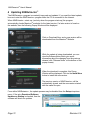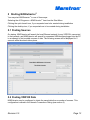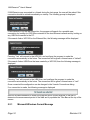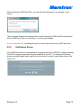
1
N2KExtractor™ Vessel Data Recorder (VDR100) Extraction Software User’s Manual Revision 2.0 Copyright © 2013 Maretron, LLP All Rights Reserved Maretron, LLP 9014 N. 23rd Ave #10 Phoenix, AZ 85021-7850 http://www.maretron.com Maretron Manual Part #: M003026 Revision 2.0 Page 1 N2KExtractor® User’s Manual Table of Contents 1 Introduction......................................................................................................................... 4 2 System Requirements ........................................................................................................ 4 3 Installing N2KExtractor™..................................................................................................... 5 3.1 Install Adobe AIR .......................................................................................................... 5 3.2 Continue Installing N2KExtractor .................................................................................. 5 3.3 Install Ext2 Device Drivers ............................................................................................ 7 3.4 Complete Install of N2KExtractor................................................................................ 11 4 Updating N2KExtractor™ .................................................................................................. 12 5 Starting N2KExtractor™ .................................................................................................... 13 5.1 Finding Sources.......................................................................................................... 13 5.2 Finding VDR100 Data................................................................................................. 13 6 6.1 6.2 5.2.1 Microsoft Windows Format Message ................................................................... 14 5.2.2 Ext2 Device Drivers ............................................................................................. 15 Screen Layout .................................................................................................................. 16 Timeline Area ............................................................................................................. 17 6.1.1 Timeline Bars ....................................................................................................... 17 6.1.2 Timeline Data Entry Fields ................................................................................... 18 6.1.3 Timeline Buttons .................................................................................................. 18 Control Area ............................................................................................................... 19 6.2.1 6.3 Control Area Buttons ............................................................................................ 19 Parameter Area .......................................................................................................... 20 6.3.1 Parameter Table .................................................................................................. 20 6.3.2 Parameter Manipulation ....................................................................................... 21 6.3.3 Select Parameter Tree ......................................................................................... 22 6.3.4 Parameter Editor .................................................................................................. 23 6.4 Map Area .................................................................................................................... 23 6.5 Graph Area ................................................................................................................. 25 6.6 Exporting to a .csv File ............................................................................................... 26 6.7 Long Running Operations ........................................................................................... 27 7 Menus............................................................................................................................... 28 7.1 File Menu .................................................................................................................... 28 7.2 Setup Menu ................................................................................................................ 28 Page 2 Revision 2.0 7.3 8 Help Menu .................................................................................................................. 29 Vessels Connections Dialog ............................................................................................. 30 8.1 Vessel Table ............................................................................................................... 30 8.2 Vessel Table Buttons.................................................................................................. 30 9 Connections Settings Dialog ............................................................................................ 32 10 Units Setup Dialog ...................................................................................................... 34 11 Technical Support....................................................................................................... 35 Revision 2.0 Page 3 N2KExtractor® User’s Manual 1 Introduction N2KExtractor™ software is a powerful and free PC-based tool for extracting data from USB Flash Drives created by Maretron’s Vessel Data Recorder (VDR100). Data can be extracted into a Comma Separated Values (.csv) file or data can be graphed and the route plotted on a map directly inside the N2KExtractor™ program. The PC running N2KExtractor™ software can access the data stored on the VDR100 USB flash drive by connecting the PC together with the VDR100 over a LAN or WAN using Ethernet, or for faster operation the USB Flash drive can be removed from the VDR100 and plugged directly into a USB port on the PC. This version of the manual applies to version 2.0 of N2KExtractor. Features: User selectable parameters User selectable units for each parameter User selects time over which parameters are extracted. o Timeline shows user selected period Data can be quickly displayed within the program o MapQuest maps show route o Up to 4 parameters map be displayed on a graph Data can be extracted to a .csv file for detailed analysis in a spreadsheet. o User selectable sample interval for extraction to .csv file. 2 System Requirements Personal Computer running Microsoft Windows 2000, XP, Vista, Windows 7, or Windows 8 1GB RAM 30 MB Hard Disk Space Internet connection (Optional for Upgrades and Viewing Routes on MapQuest maps) Page 4 Revision 2.0 3 Installing N2KExtractor™ N2KExtractor™ may be obtained free of charge from the Maretron website. http://www.maretron.com/support/downloads.php Running the installer program will take you through the following steps. Please note that N2KExtractor™ requires additional software to be installed on your PC. This other software is downloaded from the Internet so an Internet connection is mandatory when installing N2KExtractor™. 3.1 Install Adobe AIR N2KExtactor™ requires another software program called Adobe® Integrated Runtime (AIR™) from Adobe® Systems.™ If Adobe® AIR™ is not already installed on your PC, then the installer will automatically open your web browser and take you to the Adobe website. Follow the Adobe instructions to download and install Adobe® AIR™. Once you have successfully installed Adobe® AIR™, continue on with the N2KExtractor™ installer as described in Paragraph 3.2. 3.2 Continue Installing N2KExtractor Press Next. Revision 2.0 Page 5 N2KExtractor® User’s Manual After you have read and accepted the agreement, press Next. After you have selected the folder in which the installer will be installed, press Next. Page 6 Revision 2.0 After you have selected the Start Menu folder, press Next. Press Install to continue the Installation. 3.3 Install Ext2 Device Drivers The file system on the USB Flash Drive is different from the FAT file system supported by Windows. A special driver is required to access the USB Flash Drive. The N2KExtractor™ installation program will check if these drivers have been installed, and if not, the N2KExtractor™ installer will start a program to install the drivers. The EXT2FSD Disk Driver may also be downloaded from the Maretron website at <www.maretron.com/files/N2KExtractor/Ext2Fsd.exe>, and executed as a stand-alone installer. Follow the following screens. Press Next >. Revision 2.0 Page 7 N2KExtractor® User’s Manual Press Next >. Press Next >. Page 8 Revision 2.0 Press Next >. Ensure that all three check boxes contain checkmarks and press Next >. Revision 2.0 Page 9 N2KExtractor® User’s Manual Ensure that the check box contains a checkmark and press Finish. The above dialog is a monitor that shows the storage volumes on your computer. The monitor is not required to be running for the Disk Driver to function, so you can close it by clicking of the red X at the top right after confirming that the drivers have been installed correctly. To confirm that the Ext2 File System drivers have been installed correctly: Insert the USB Flash Drive created by the VDR100. In the Ext2 Volume Manager you should be able to see the EXT3 file system. (F: in the screenshot above). Using the Windows file system Browser (Windows Start Computer) , check that you can see the drive and that its contents are visible. If the drive and its contents are not visible, a restart of your computer may be required. Page 10 Revision 2.0 3.4 Complete Install of N2KExtractor The following Popup Window will be shown. Click on Install to continue with the installation. Select your installation preferences and location, and then click on Continue. When the installation of N2KExtractor™ is complete, it will start automatically. If you selected to add a Shortcut icon to your desktop, you will see this icon your desktop. Revision 2.0 Page 11 N2KExtractor® User’s Manual 4 Updating N2KExtractor™ The N2KExtractor™ program is constantly improved and updated. If you want the latest update, be sure to start the N2KExtractor™ program while the PC is connected to the Internet. When N2KExtractor™ starts up, (and only when the program starts up) the program automatically checks Maretron®’s website for the latest version. If a later version is found on the website, then the following Popup Window will be displayed. Click on Download Now, and a new version will be downloaded from the Maretron® Website. While the update is being downloaded, you can view the Release Notes which give some information about the changes from the previous release (click “Release Notes” at the bottom of the popup screen). When the download is complete, this Popup Window will be displayed. Click on the Install Now button to install the new version. The previous version of N2KExtractor™ will be automatically closed, and the new version started with the same file open. From within N2KExtractor™, the update process may be disabled from the Setup drop down menu. If the entry Download Software Updates on Startup is checked, then the software will check for updates. Page 12 Revision 2.0 5 Starting N2KExtractor™ You may start N2KExtractor™ in one of three ways: Selecting the All Programs N2KExtractor™ item from the Start Menu Clicking the quick launch icon, if you requested one to be created during installation Clicking the desktop icon, if you requested one to be created during installation 5.1 Finding Sources On startup, N2KExtractor will search the local Ethernet network for any VDR100’s connected to that network, and N2KExtractor will search for connected USB devices plugged into the PC in an attempt to find possible sources of data. The following screen will be displayed for 5 seconds while the search takes place. 5.2 Finding VDR100 Data N2KExtractor may be configured to obtain the saved data from a number of sources. This configuration is saved in the Vessels Connections Dialog (see section 8). Revision 2.0 Page 13 N2KExtractor® User’s Manual If N2KExtractor was connected to a Vessel during the last usage, the user will be asked if this connection should be retried immediately on startup. The following prompt is displayed. If user declines to try the last connection, the program will search for a possible new connection, by looking for VDR100s connected to the local Ethernet network and by looking on any USB Drive inserted in the PC. If the search finds a VDR100 on the Ethernet Bus, the following message will be displayed Pressing “Yes” will connect to that VDR100, and configure the program to make the connection automatically in the future. The connection will be given a Vessel name of “default”. If the search finds a USB Drive that was created by a VDR100, then the following message is displayed: Pressing “Yes” will connect to the USB Drive, and configure the program to make the connection automatically in the future. The connection will be given a Vessel name of “usb”. Once connected the configuration can be changed in the Vessels Connections dialog. If no connection is made, the following message is displayed As soon as valid connection is made, the program will do a quick analysis of the disk to determine the measurement period of the data and it populates the Time Bars at the top of the screen. 5.2.1 Page 14 Microsoft Windows Format Message Revision 2.0 When inserting the USB Flash Drive, you may see the following pop-up message on your screen. This is because Windows has detected the unusual format of the USB Flash Drive and thinks that the USB Flash Drive is un-formatted. You must press Cancel Do not Format the disk. Formatting will wipe out all the data saved on the USB Flash Drive. 5.2.2 Ext2 Device Drivers If the USB Flash Drive is not recognized as containing data from a VDR100, it may be because the Ext2 File system drivers have not been installed on your PC. You will see the following prompt; pressing Yes will open a pdf file with instructions on how to install these drivers. (see section 3.3) Revision 2.0 Page 15 N2KExtractor® User’s Manual 6 Screen Layout The N2KExtractor screen is divided into 4 areas, shown here after a connection has been established. The division (indicated in yellow) between the Parameters / Map Area and the Graph Area may be dragged up and down to customize the height of the respective windows. Page 16 Revision 2.0 6.1 Timeline Area This area is used to select the time interval over which the data will be extracted. 6.1.1 Timeline Bars The Timeline Area consists of two timeline bars, each with highlight areas, and a yellow cursor with a display of the date and time. When a connection is made, the program will quickly analyze the data and show in the upper bar (the Overall Context bar) the time period covered by the data. The times represented by the ends of the top Time Bar are fixed by the data on the Flash Drive. Each highlight area may be dragged left or right by “grabbing” near the center of the highlight area, and the ends may be moved by “grabbing” on the small boxes (handles) at either end of the highlight. By moving the ends, the period of time represented by the highlight may be changed. Initially the highlights are set to cover about one third of the full extent of the Time Bar. Pressing the Zoom All button will expand them to cover the entire time span. The yellow cursor may be dragged by grabbing the yellow box containing the date and time and dragging it left or right. Dragging the yellow cursor on one Time Bar will move the yellow cursor on the other Time Bar to keep them synchronized in time. Right-clicking with the mouse on the yellow cursor will bring up the following menu: Clicking on Set as start of period will move the start of the user selected extraction period to the position of the yellow cursor. Clicking on Set as end of period will move the end of the user selected extraction period to the position of the yellow cursor. Top Time Bar: The top Time Bar has a double highlighted area. The light blue area corresponds to the extents of the time shown in the bottom bar. By dragging the left and right handles of this highlighted area, changes the total period represented by the bottom Time Bar. This enables you to “zoom in” for more accurate time interval selection. The lower turquoise area corresponds to the time selected from which the data will be extracted. In a similar way, the Lower Time Bar (the Zoomed Context bar) just contains the light blue area and the turquoise area. This means that the lower Time Bar is a zoomed in view of the top Time Bar. The turquoise area of the bottom Time Bar corresponds to the turquoise area of the Top Time Bar; either can be used to define the time period from which the data will be Revision 2.0 Page 17 N2KExtractor® User’s Manual extracted. The dates and times of the turquoise area are displayed just under the bar as the Period. 6.1.2 Timeline Data Entry Fields The data entry fields are positioned just below the timelines. Period: The start and end date and time are shown here. These values are synchronized with the highlight area of the lower time bar. You may type specific values in these fields to define the start and end times, and the bars above will follow. When the backgrounds of these fields are red, the contents are invalid (e.g. a month may be spelled incorrectly). When the text is red, the time period represented by previously extracted data does not match the values in the Period boxes. The format of the dates may be changed in the Units Dialog. 6.1.3 Timeline Buttons There is one button on the right of this area. Zoom All: This sets the highlight bars so that they cover the full period of the Flash Drive Page 18 Revision 2.0 6.2 Control Area This area is used to display messages to the user (on the left), and is home to the buttons used to instruct the program (on the right). The control area buttons change depending on whether the Parameter or Map is active within the Parameter/Map Area. The following are available if the Parameters tab is active. The following buttons are available if the Map tab is active. If the text on the buttons is red, then the displayed data is out of sync with the timeline and should be refreshed by pressing that button. 6.2.1 Control Area Buttons The definition of the four buttons found within the Control Area are as follows. Find Params: Pressing this button will extract recorded parameters for all the recording period chosen in the Timeline Area, and populate the Parameters Area. This can be a very long operation if the network is extensive and the period is long. A suggestion is to choose a small period (1 to 2 days) when you know that all devices are active on the bus, and find the parameters in this period only. Unless you are changing devices on the bus frequently, this set of parameters will apply over the entire recording. Once you have established a good set of parameters, save them to disk (see section 6.3.2). Whenever the recording period is changed, the text in the button will be made red, indicating that the data displayed is not synchronized with the Period shown in the timeline. Update Route: Pressing this button will extract GPS data for the chosen recording period, and display the route on a Map. The maps are downloaded from MapQuest, and require an Internet connection. Whenever the recording period is changed, the text in button will be made red, indicating that the data displayed is not synchronized with the Period shown in the timeline. Graph Params: This extracts data and creates graphs in the graph area. The parameters that are extracted must be selected in the Parameters are before this button is pressed. Only the top four selected parameters will be graphed. Whenever the recording period is changed, the text in button will be made red, indicating that the data displayed is not synchronized with the Period shown in the timeline. Export Params: This extracts the data for all the selected parameters to a csv file (see section 6.6). Revision 2.0 Page 19 N2KExtractor® User’s Manual Whenever the recording period is changed, the text in button will be made red, indicating that the data displayed is not synchronized with the Period shown in the timeline. 6.3 Parameter Area The Parameter Area is shared with the Map Area. Select the Parameters tab to display the Parameters Area. The Parameter Area may be populated in a number of ways. If you know the parameters that are stored by the VDR100 and the respective instance numbers, you may add them manually to the table using the “Add” button. Remove them from the table using the “Delete” button. The “Find Parameters” button in the Control Area (see section 6.2.1) will search and populate the table with all the possible parameters that are stored. Once the table is populated, it may be saved, and then loaded later. 6.3.1 Parameter Table Parameter selection is done in a table. The table may be sorted on any column by double clicking the header of that column. The column widths may be changed by dragging the lines between headers. The table has the following columns: Use: Only parameters with the checkbox selected will be used for data extraction. If the data is displayed in the Graph Area, the check mark will be black; if not displayed then it will be red. Title: The title that will be shown on the graph for the parameter Label: The label of the parameter (if present on the NMEA2000 bus). Parameter: The category and name of the parameter Page 20 Revision 2.0 Unique Instance: The instance number of the parameter. If we have recorded a label for this instance from the device, then the label is appended to the instance number in parenthesis. Source / Indicator: Where the parameter requires extra source or indicator values to fully define it, these are displayed in this column (e.g. a number of Circuit Breakers will be reported from the same instance, and each has a specific indicator number, or tank levels have different fluid types). Units: The units in which the data will be displayed. The Search box may be used to search for values in the Title, Label and Parameter columns. 6.3.2 Parameter Manipulation Buttons under the table allow the data in the table to be manipulated. Unselect All: This removes the Use checkmarks from all the entries in the table. Clear: The parameter table will be cleared. Add: Press this to manually add a parameter to the table. This will display a tree structure (similar to N2KView) from which you can choose the parameter to add to the list. If a row in the table has been selected, then the new parameter is added immediately following the selected row, otherwise it is added at the end of the table. (See 6.3.3) Edit: If a row in the table has been selected, pressing this button will display an editor in which the parameter details maybe edited. (See 6.3.4) Move Up: The highlighted row is moved up in the table. Because only the top 4 selected rows will be graphed, this can be used to move a desired parameter above other parameters Move Down: The highlighted row is moved down in the table. Load: The contents of the Parameter table may be loaded from disk. Save: The contents of the Parameter table may be saved to an .n2e file on disk. Revision 2.0 Page 21 N2KExtractor® User’s Manual 6.3.3 Select Parameter Tree Adding a parameter by pressing the Add button displays the Select Parameter Tree similar to that used to select parameters in N2KView. The yellow folders represent the different categories of data, and within each category is the list of parameters. Clicking on a yellow folder will either open or close the folder. Clicking on a parameter will open the Parameter Editor (see 6.3.4) for that parameter. Page 22 Revision 2.0 6.3.4 Parameter Editor This is similar to the parameter editor in N2KView. Title: The title of the parameter on the graph. This is user defined. Use Label: If selected, the graphs will be created using the label field for the series name; if not selected, the Title will be used. Units: The units in which the data will be displayed. This is populated from a list of default units, set in the Units Dialog (see section 10). Instance: The unique instance number of the parameter Indicator: If applicable, this is used to identify the indicator within the instance number. Save: Pressing this button enters the new data in the table or overwrites the old data. Cancel: Pressing this button exits the editor without saving any data. 6.4 Map Area The Map area is shared with the Parameter Area. It displays a map showing the vessels route over the data extraction period. Select the Map tab to display the Map Area. Revision 2.0 Page 23 N2KExtractor® User’s Manual This area displays a simple map from MapQuest showing the position of the vessel at the yellow cursor position of the Timeline Bars, and the route of the vessel over the extraction period in yellow. The marker for the vessel may be dragged on the route, and the cursor position on the Timeline Bars and Graph will follow. Clicking on the map with the left button of the mouse will position the marker for the vessel at the closest route position to the cursor. The yellow cursor positions will synchronize to this time. Clicking on the map with the right button of the mouse will allow the map to be printed. The map is annotated with the position of the vessel in Latitude and Longitude, plus any parameters that have already been extracted to the Graph Area. An internet connection is required to display the map. The map may be zoomed, moved or scrolled using the controls provided on the map. Page 24 Revision 2.0 6.5 Graph Area Up to four parameters may be graphed at once. The graph is populated by selecting parameters (see section 6.3.1) and pressing the Extract button (see section 6.2.1). Once the graph has been drawn, more detail can be seen by hovering over a point on the graph with the mouse. The horizontal axis of the graph represents time. Where the timeline extends over multiple days, the date will be added to the time. Vertical axes are minimized wherever possible by combining axes of the same data type (e.g. two temperature values will be combined on the same axis at the same scale). Different data types will create different axes, alternating in placement between the left and right of the graph. The yellow, vertical line may be dragged over the graph. The markers on the Timelines and vessel position on the map will be moved to stay in sync with the yellow line. Clicking on the graph with the left button of the mouse will position the markers at the mouse position. Clicking on the yellow line with the right button of the mouse will display the following menu: Clicking on Set as start of period will move the start of the user selected extraction period to the position of the yellow cursor. Clicking on Set as end of period will move the end of the user selected extraction period to the position of the yellow cursor Clicking on one of the labels just able the graph will cause that parameter to be drawn on top of the other parameters of the graph. Revision 2.0 Page 25 N2KExtractor® User’s Manual 6.6 Exporting to a .csv File A CSV file is a comma separated values file suitable for importing into a spreadsheet program such as Microsoft Excel. The file has a .csv extension. Because Excel has a limit of 32000 records per file, the data may be broken up into more than one csv file. These will be numbered sequentially. Pressing the Export Params button will show the Export to CSV File Dialog. Extraction Interval: Over long periods, if every single data point was extracted, the graphs or extracted data would result in long processing times and excessively large files. From the period selected by the timeline bars or Period fields, the Extraction Interval is pre-populated to give about 1000 entries. This may be changed by the user to increase or decrease the number of points in the files. Decreasing the interval will increase the processing time. Setting a value of zero (0) will cause every point to be extracted. Note that the time taken to fetch and process the data will increase as the number of sample points increases. Setting a very small sample interval may cause the program to run very slowly. Filename: The data will be stored in this file. Select the filename by typing, or by pressing the Browse button. Extract button. The data extraction will take place when this button is pressed. Cancel button. This returns you to the main screen without doing the extraction. Page 26 Revision 2.0 6.7 Long Running Operations Long running operations will display the following dialog while they are executing. If it is possible to estimate the time remaining in the current operation, this estimate will be displayed as part of the message. Note that this is an estimate; gaps in the data and other factors in the VDR100 will cause errors in the value displayed. Press the Cancel Button to cancel the operation. If the operation has requested data from the VDR100, the operation cannot be cancelled until the data is returned. You will be informed that your request to cancel has been noted, and the dialog will be removed when the VDR100 responds. Revision 2.0 Page 27 N2KExtractor® User’s Manual 7 Menus Drop down menus are accessed from the menu bar at the top of the screen 7.1 File Menu The first three entries manage databases produced by the VDR100. Open VDR100 Database (Flash Drive/Hard Disk): This opens a dialog from which the user can choose to open a database from a VDR100 Flash drive plugged into the PC running the N2KExtractor program, or the user can select a database previously saved to the hard drive. Open Demo Database: This opens the database containing demonstration data. Save VDR100 Database As: This saves the currently opened VDR100 database to the hard drive. The user will be prompted to enter a filename for the database. Erase USB Flash Drive: The USB Flash Drive will be marked for erase by the VDR100 when it is next inserted into the VDR100. The user will be prompted to confirm this operation. This entry will only be displayed when connected to a USB Drive. Connect to a Vessel: This opens the Vessels Dialog, which is explained in section 8. Create CSV File: This extracts the parameters defined in the current configuration and creates a CSV (Comma Separated Values) file with the extension .csv containing the data extracted. This file can be imported into a spreadsheet program such as Excel for further analysis. Because Excel has a limit of 32000 records per file, the data may be broken up into more than one csv file. These will be numbered sequentially. Exit: Exit the program. 7.2 Setup Menu Set Default Units: This opens a dialog in which the default units and date format can be set (see section 10). Vessels: This button opens the Vessels Connections Dialog, which is described in section 8. Download Software Updates on Startup: When checked, the N2KExtractor program will look for program updates on the Maretron web page every time it is started. If an update is detected, then the user will be asked if the updates should be downloaded and installed (see section ). Page 28 Revision 2.0 7.3 Help Menu How to Install USB Flash Drive Driver: Displays a pdf file containing instructions on how to install the drivers for the Ext2 File System used by the USB Flash Drive. Open User’s Manual: Opens the N2KExtractor User’s Manual in a separate window. About N2KExtractor: Displays the About Dialog. This shows the software version number of the program. Revision 2.0 Page 29 N2KExtractor® User’s Manual 8 Vessels Connections Dialog In version 2.0 of N2KExtractor, Maretron introduces the concept of Vessel Connections. For fleet managers using N2KExtractor, each vessel in the fleet is given an entry in the Vessels Connections table, and named. This information is stored so that it is always available to make connecting to different vessels as simple as possible. For each vessel, up to two different ways of connecting may be specified, to allow for on-board or remote connections without having to reconfigure. 8.1 Vessel Table The Vessel Table has three columns Vessel Name: This is the user supplied name of the vessel. Connected: This column shows which of the vessels are currently connected to N2KExtractor. Only one vessel may be connected at a time. The status of the VDR100 will be displayed for the connected VDR100. Parameter File: If the parameter configuration file has been saved while connected to a vessel, the filename is recorded in this column. 8.2 Vessel Table Buttons New: Press this button to create a new entry in the Vessel Table. The Connections Settings Dialog will be opened (see section 9). Page 30 Revision 2.0 Edit: If a vessel has been selected in the table, it may be edited by pressing the Edit button. The Connections Settings Dialog will be opened (see section 9). Delete: If a vessel has been selected in the table, it may be deleted by pressing the Delete button. A confirmation dialog will be displayed to prevent accidental deletions. Connect / Disconnect: If a vessel is selected in the table, and that vessel is connected to N2KExtractor, the Disconnect button can be used to disconnect from the vessel. If no vessels are connected, then the Connect button can be used to attempt to make a connection. Close: This button closes the Vessels Connections dialog box. Revision 2.0 Page 31 N2KExtractor® User’s Manual 9 Connections Settings Dialog The Connections Settings Dialog is used to manage the connections to a single vessel. In the following diagram, the connections settings dialog is shown in the disconnected state. Most changes to the connections may only be made while disconnected. The dialog is divided into four areas: Vessel Name: The name by which this vessel is identified in the Vessels Connections dialog. Available Connections: N2KExtractor will attempt to identify all the VDR100 devices on the Ethernet, and list them here to help make connecting to a VDR100 as easy as possible. If a valid USB drive has been plugged into the PC it will also be listed. Select an entry in the table and press one of the “Use Selected” buttons to transfer this data to the Connection area. Connection Area: This area contains two identical lines, to allow two options to connect to the same vessel. If the option is to be considered as a way to connect to the vessel, the checkbox on the left must be checked. If it is not checked, the line will be ignored. If the VDR100 has been set up with a password, then the password must be entered in the Password field before the VDR100 will supply data. The contents of each line will change based on the method of connection. Page 32 Revision 2.0 LAN: If the VDR100 is on the same network as the PC running N2KExtractor, it is best to identify the VDR100 by its Serial number. This way, if the network controller assigns a new IP address to the VDR100, N2KExtractor can still find it on the network and connect to it. WAN: If the VDR100 is on a different network to the PC, it may be accessed via a bridge with port forwarding. The WAN option allows the entry of the IP address and port number required by the bridge. This method may also be used to access a VDR100 on the same network using its IP address. USB Drive: If the data is to be read off a USB Drive plugged in to the PC, this option should be chosen. When connecting to the vessel and both lines are selected, N2KExtractor will attempt to make one connection after the other until a connection is successfully made. Connection State: This is a display area containing messages about the state of the connections, and buttons to enable the connection to be made (Connect) and broken (Disconnect). This is an example of the connection state to a VDR100, when connected using the LAN method. The VDR100 is busy recording. Revision 2.0 Page 33 N2KExtractor® User’s Manual 10 Units Setup Dialog While it is possible to customize units for each parameter in which the data is presented (see section 6.3.4), this dialog provides a way to set common units that will be used as defaults. Note that changing the defaults after the Parameter Table is populated does not change anything already in the table. Language – for now, the language is restricted to English Date Format – This controls how the dates are presented on all the dialogs and graph X axis. Options include showing the month as two digits (MM) or three characters (MMM) (e.g. “Jan”), and having the month before or after the date. Time Format – This controls how the times are presented on all the dialogs and graph X axis. Options are to show the time in a 12 hour format with “am” or “pm”, or to show time in a 24 hour format. Page 34 Revision 2.0 11 Technical Support If you require technical support for Maretron products, you can reach us in any of the following ways: Telephone: 1-866-550-9100 Fax: 1-602-861-1777 E-mail: [email protected] World Wide Web: http://www.maretron.com Mail: Maretron, LLP Attn: Technical Support 9014 N. 23rd Ave Suite 10 Phoenix, AZ 85021 USA Revision 2.0 Page 35