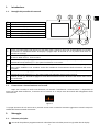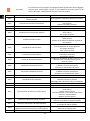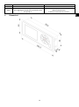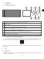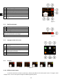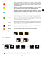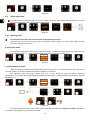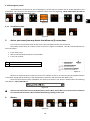
1
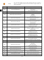
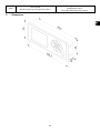
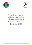
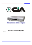
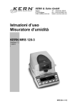
Manuale di istruzioni. User manual. UNE EN 14785 1 VI CONSIGLIAMO DI LEGGERE L'INTERO MANUALE DI ISTRUZIONI PRIMA DI INSTALLARLO E USARE IL VOSTRO STUFA A PELLET (BIOMASSA). WE ADVISE TO READ THE WHOLE INSTRUCTION MANUAL BEFORE TO INSTALL IT AND USE YOUR PELLET (BIOMASS) STOVE. 2 Pagina 4. Page 13. 25/6/2.015 3 ÍNDICE 1.- Introduzione. Pagina 6 2.- Maneggio. Pagine 6-10 3.- Collegarsi da un sistema wi-fi (cellulare, tablet, computer, ecc). Pagina 10 4.- Allarmi. Pagine 10-12 5.- Dimensioni (mm). Pagina 12 INDEX 1.- Introduction. Pages 14 2.- Use. Page 14-18 3.- Connect from a wi-fi system (phone, tablet, computer, etc.). Pages 18 4.- Alarms. Pages 18-20 5.- Dimensions (mm). Page 20 4 Manuale dell'utente. Questo apparecchio può essere utilizzato dai bambini a partire dagli 8 anni di età e da persone con capacità fisiche, sensoriali o mentali ridotte o che non abbiano esperienza o conoscenza, sempre sotto la supervisione o con la formazione adeguata riguardo all’utilizzo sicuro dell’apparecchio e con la corretta comprensione dei pericoli che può comportare. I bambini non devono giocare con l’apparecchio. La pulizia e la manutenzione da effettuare da parte dell’utente non devono essere effettuate dai bambini senza supervisione. Il vetro della porta e alcune superfici dell’apparecchio possono raggiungere alte temperature. ATTENZIONE!: non dell’apparecchio. aprire la porta durante il funzionamento Legga attentamente il presente manuale di istruzioni prima di utilizzare l’apparecchio. Solamente in questo modo potrà ottenere le migliori prestazioni e la massima sicurezza durante il suo impiego. 5 1. Introduzione. 1.1. Dettaglio del pannello dei comandi. Display. Pulsante indietro / movimiento sinistra. Pulsante aumento / sopra. Pulsante Avanti / movimento destra. Pulsante diminuzione / giù. Pulsante on-off / conferma. Ricevitore IR. (Disabled). Figura 1 1.2 Display a cristalli liquidi (LCD). Riporta lo stato della stufa e riflette le azioni che intraprendiamo sul pannello di controllo. La retroilluminazione del display si spegne dopo 30 secondi se non si preme alcun tasto sul pannello di controllo. Pulsante indietro (). Permette di accedere a la visualizzazione dei dati o fa il movimento verso la sinistra all'interno delle icone o i diverse menu. Pulsante aumento / sopra. (). Aumenta il valore di potenza desiderato e / o la temperatura, secondo la modalità di funzionamento (P, T o E) e sposta la selezione su nei menu. Pulsante Avanti (). Permette di accedere al menu Impostazioni e tornare alla schermata principale del menu senza modifiche. Puo accedere anche alla modalità di funzionamento dalla schermata del menu principale. Pulsante diminuzione/giù (). Diminuisce il valore di potenza desiderato e / o la temperatura secondo la modalità di funzionamento (P, T o E) e sposta la barra di selezione verso il basso nei menu. Pulsante on-off (). Accende e spegne la stufa dalla schermata iniziale. All'interno dei diversi menu serve per confermare. Ricevitore IR. Riceve il segnale inviato dal telecomando. (disabile). Connessione e sincronizzazione con la stufa. Dopo aver installato la stufa come descritto nel manuale "Installazione e manutenzione" * disponibile sul nostro sito web www.netflame.it, la tastiera sarà in funzione in un tempo sotto 40 secondi dal collegamento della stufa alla rete. Figura 2 * Si prega di notare che sul nostro sito si possono trovare tutti i manuali di istruzioni aggiornati. Prevarrà sempre la validità dell'ultimo manuale di istruzioni. 2. Managgio. 2.1. Schermo principale. Si ricorda che qualsiasi programmazione di calendario fatta sul tablet prevarrà su gli ordini dati al display. 6 Barra di lettura dei messaggi. Modo P, T o E. Stato (Vedere diversi stati). Livello di potenza / Temperatura desiderata. Tastiera bloccata. Schermo principale. Temperatura interna letta dalla sonda camera. Figura 3 2.2 Barra lectura de mensajes. Messaggio di sicurezza. (N o Axx).* Modo di funzionamento (P, M o E).** Stato di funzionamiento. *** *Alarmas (Axx) (punto 4). **Potenza, temperatura o emergenza, puntos 2.10.1, 2.10.2 y 2.10.3 rispettivamente. *** Diversi stati nei punti 2.4.1. 2.3. Figura 4 Schermata di selezione della lingua, modo, carburante, ecc. Selezione di lingua. Spagnolo (predefinito) (6 disponibli) Modo di funzionamiento (P, M o E) Test motori (per il S.A.T.) Selezione di combustibile. Pellet (predefinito) nocciolino di oliva o gusci di mandorle. Impostazioni dei diverse ‘offset’. Ritorno alla schermata principale Figura 5 2.4. Avviare. Figura 6 2.4.1. Diferentes estados de la estufa. Per realizzare l’accensione dobbiamo premere il pulsante (pulsante on-off ) sul panello di controllo. Il ponto della figura 4 il suo colore cambierà a misura che passa per le diverse fasi di accensione. 7 In prima istanza e quando la stufa è spenta e pronta per essere accesa Rosso 2.5. visualizzeremo la menzionata icona di colore rosso. Se premiamo la tecla , l’elettronica farà una breve verifica di motori e depressione di aria e procederà a realizzare l’accensione, cambiando l’icona da bianco a giallo. Giallo Quando l’icona passa a colore giallo ci indica che la stufa sta realizzando una accensione con l’estrattore, caduta di combustibile e resistenza di accensione funzionando per conseguire la combustione iniziale. Azzurro celeste Una volta che otteniamo una differenza di temperatura rispetto a quella registrata nel momento dell’accensione, l’icona cambierà a un colore azzurro celeste indicando che si trova in processo di preriscaldamento, spegnerà la resistenza di accensione e si realizzerà un processo totalmente automatizzato per conseguire una combustione adeguata per il successivo funzionamento. Verde Quando la temperatura nell’uscita di gas raggiunge i 100°C e trascorrono 6 minuti dall’accensione, l’icona cambierà a un colore verde il che ci indica che si è concluso il processo di accensione e avremo accesso alla regolazione di caduta di combustibile o alla regolazione della temperatura. Nel caso in cui non si raggiunga la suddetta temperatura in 15 minuti passerà a indicare l’allarme 99 (A099). Vedere tabella degli allarmi (punto 4). Bianco Quando si esegue lo spegnimento della stufa, l'icona diventerà successivamente bianca e dopo rossa. L’icona diventerà blu se la stufa si spegne per temperatura e arancione se è emerso un allarme. Blu Indica che è in attesa della programmazione. Leggere il punto 2.5, 2.6 e 3 del “Manuale di utente tablet”. Arancione Questa icona è accompagnata da una segnalazione del messaggio di sicurezza. Vedere punto 4 allarmi. Spegnimento. Figura 7 2.6. Attivare o disattivare il blocco della tastiera. Figura 8 2.7. Selezione di lingua. Figura 9 2.8 Sostituzione del combustibile. 8 Dovrebbe tenere a mente che potrebbe essere necessario aggiungere un accessorio per utilizzare un altro combustibile. Prima di procedere a tale cambiamento consultare il vostro distributore. Figura 10 2.9. Impostazione offsets. Queste regolazioni devono essere puntuali, perché la stufa viene regolata automaticamente, nel caso di dover effettuare una regolazione contattare il distributore. Figura 11 2.10. Modo di funzionamento. Per accedere a questo menu, la estufa deve essere spenta e non mostrare nessun allarme. L’elettronica ha tre modalità: potenza, temperatura e emergenza. Per selezionare un modo o l'altro, si accede dalla schermata iniziale: 2.10.1.Modo potenza. Il campo di regolazione va dal livello 1 al 9, 9 è il più alto livello di caduta del combustibile. Per aumentare il livello premere la freccia () e per abbassare la freccia verso il basso (). Figura 12 2.10.2.Modo temperatura. Se si imposta la modalità di funzionamento a temperatura, P sarà sostituito da un T. Solo dobbiammo impostare questa modalità se si è collegata la sonda camera o il termostato libero di tensione e con il adattatore correspondente. Il campo di regolazione della sonda è compreso tra 12 ° C e 35 ° C, quest'ultima essendo la temperatura massima regolabile. Per aumentare la temperatura premere la freccia () e per abbassare premere la freccia verso il basso (). Figura 13 Figura 14 9 Per una regolazione più precisa di questo modo, fare riferimento ai paragrafi 2.5 e 2.6 del "manuale tablet per l'utente", a disposizione sul nostro sito web www.netflame.it, o contattare il vostro distributore. 2.10.3.Modo de emergenza. Questo modo si deve utilizzare solo in caso di emergenza, giacché non memorizza la depressione di entrata di aria, modulazione del combustibile, il convettore funzionerà alla massima potenza dall’inizio.. USARE SOLO IN CASO DI EMERGENZA E COME INDICATO DAL S.A.T. Figura 15 2.11. Visualizzazione di dati. Figura 16 3. Collegamento alla stufa da qualsiasi dispositivo che permette il collegamento wireless. La prima cosa che serve è sapere l'identificazione della rete wireless della stufa (SSID) e la password per la rete. La può trovare su un adesivo (sticker) simile all’esempio in figura 5, con la password per la connessione Wi-Fi della stufa in 3 posti: • • • CPU della estufa. Accanto al adesivo con il numero di serie della macchina. Nel manuale di utente. Identificazione rete Wi-Fi stufa (SSID). Password rete Wi-Fi stufa (PWD). Figura 17 Dobbiamo trovare e connettersi alla rete senza fili dalla stufa, quindi dobbiamo inserire la password indicata sull'adesivo, rispettando tutti i caratteri alfanumerici della password ed è case sensitive. Una volta la connessione è stabilita, immettere sul browser Web del vostro dispositivo, l'URL: http://192.168.3.1 Figura 18 Se il dispositivo è utilizzato con più reti (stufa, wifi di casa, wifi lavoro, ecc) si deve garantire che quando facciamo qualcosa sulla stufa , questa deve essere collegata alla stessa rete wifi. 4. Allarmi. Figura 19 10 Arancione Allarme A000 ILe menzionate icone vengono accompagnate dalla segnalazione del messaggio di sicurezza Axxx, vedere figura 4 punto . Può indicare un'avaria dei sensori o dei motori della stufa. Vedere tabella che viene inclusa di seguito. Descrizione Si visualizzerà in caso di spegnimento con un allarme attivato. A001 Depressione di entrata di aria bassa A002 A003 Depressione di entrata di aria alta Temperatura di uscita di gas minima. A004 Temperatura di uscita di gas massima. A005 Temperatura NTC minima. A006 Temperatura NTC massima. A007 Pressione di acqua minima. A008 Pressione dell’acqua massima. A009 Temperatura ambiente minima. A010 Temperatura ambiente massima. A011 Temperatura CPU minima. A012 Temperatura CPU massima. A013 A014 Corrente dei motori al di sotto del minimo. Corrente dei motori al di sopra del massimo. A015 Depressione di entrata d’aria molto bassa. A016 Allerta per temperatura di gas massima. A017 Allerta per temperatura di acqua massima. A018 A019 L’estrattore arriva al 100% e non raggiunge la depressione minima di lavoro in modo continuo. Estrattore dell’uscita dei gas al 100% 11 Soluzione NON spegnere, utilizzare il bottone di sicurezza. Pulire stufa. Porta aperta. Tubo di uscita dei gas sporco. Eccesso di aria nell’istallazione La stufa è rimasta senza pellet. È ecceduta la temperatura massima di lavoro. Stufa sporca. Uso troppo intensivo. Installazione della caldaia non correttamente dimensionata. Caldaia che funziona a livelli bassi di potenza. NTC avariata. Aria nel circuito. Poca dissipazione di energia generata Uso troppo intensivo. NTC in cortocircuito. Riempia il circuito di riscaldamento. Pressostato sconnesso. Pressostato avariato. Scendere la pressione di lavoro tra 1.2 e 1.5 bar Montare vaso di espansione più grande. Aria nel circuito. C’è poca temperatura nella stanza. Inabilitare la sonda di ambiente. Diminuire la temperatura di lavoro. C’è troppa temperatura nella stanza. Inabilitare la sonda di ambiente. Aumentare la temperatura di lavoro. Temperatura della CPU al di sotto del minimo. Sporcizia nella stufa. Convettore sporco o avariato. Montaggio del tubo di uscita di gas inadeguato. Revisionare le connessioni dei motori. Revisionare il cortocircuito nei motori. Depressione minima per il funzionamento. Stufa sporca. Tubo di scarico sporco. Porta del focolare o cassonetto porta-cenere chiusi non correttamente Registro di pulizia aperto. Ha raggiunto la temperatura di uscita di gas di sicurezza e scenderà la caduta dei pellet. Ha raggiunto la temperatura di acqua di sicurezza e scenderà la caduta di pellet. Stufa/caldaia sporca. Effettuare la manutenzione. Stufa/caldaia sporca. A020 A099 5. Errore nei sensori. Mancanza di pellet. Non raggiunge la temperatura minima di uscita dei gas 80 °C. Dimensioni. 12 Effettuare la manutenzione. Possibile interscambio di sensori. Riempire la tolva. Motore ridotto fermo. È saltato il termostato di sicurezza. User Manual. This appliance can be used by children aged from 8 years and above and people with reduced physical, sensory or mental capabilities or lack of experience and knowledge if they have been given supervision or instruction concerning the use of the appliance in a safe way and if they understand the hazards involved. Children shall not play with the appliance. Cleaning and user maintenance shall not be made by children without any supervision. The glass door and some other surface areas of the appliance may reach high temperatures. WARNING: Do not open the door while the appliance is operating. Read carefully this manual before using the appliance. Only that way, the best performance and maximum safety will be got during its use. 13 1. Introduction. 1.1. Details of the control panel. Display. Back button / leftwards Increase button / upwards Forward button / rightwards Decrease button / downwards ON - Off button/ confirm Infrared receptor. Figure 1 1.2 LCD screen. It shows the stove status and reflects the actions taken on the control panel. The sreen’s backlight goes off after 30 seconds of inactivity on the control panel. Back button (). It allows access to the menu, data viewing or leftward movement among the icons or the different menus. Increase button / upwards (). Increases the desired power /temperature value according to the operating mode (P, T or E) and moves the selection upwards in the menus. Forward button / rightwards (). It allows acces to the adjustments menu and returns to the main screen from the menus without modifications. It also accesses the working menu without making any changes and goes to the “working mode” menu from the main screen. Decrease button / downwards (). Decreases the desired power /temperature value according to the operating mode (P, T or E) and moves the selection downwards in the menus. ON - Off button/ confirm (). Turns the stove on and off from the main screen. It allows confirming the actions taken, within the different menus. Infrared detector. Receives the signal sent by the remote control. Disabled. Connecting to and synchronizing with the stove. After installing the stove as described in the "Installation and maintenance manual" available in our website www.netflame.it*, keyboard is operating for under 40 seconds from the connection of the stove to the mains. Figure 2 * Please note that all updated user manuals are available in our website.. Siempre The last versión of the manual will always prevail. 2. Use. 2.1. Main screen. Please, remember that any calendar programming done with the tablet will prevail over the instructions given to the LCD display. 14 Message Reading bar. P, T or E modes Status (see list) Target power/temp. level Keyboard blocked Main screen. Inhouse temperatura read by the room probe. Figure 3 2.2. Reading messages. Safety message. (N or Axx)*. Operating mode (P, M o E). ** Working status. *** * Alarms (Axx) (point 4). ** Power, temperature or emergency, 2.10.1, 2.10.2 and 2.10.3 points accordingly. ***Different status in point 2.4.1. 2.3. Figure 4 Language/ mode/ fuel screen. Language selection (spanish by default) 6 available. Working mode(P, M or E) Engine tests (meant for T.S.)(Technical Serv.) Fuel selection. (pellet, olive pits or almond shells (pellet by default) Different ‘offsets’ adjustments. Return to main screen. Figure 5 2.4 Turn On. Figure 6 2.4.1. Different stove status. To turn the stove on we have to push the button (On-Off) on the control panel. Point of figure 4 will change colour, as trhe stove goes through the different ignition phases. 15 Red At first, when the stove is off and ready to be turned on, we will see the above mentioned icon in white. If we press the key, the electronics will Shortly Verify the engines and air depression and will start the device, turning the icon color from white into yellow. Yellow When the icon is yellow it means the stove is being turning on with the extractor, fuel drop and ignition resistance in order to obtain the initial combustion. Sky blue Once there is a difference of temperature regarding the temperatures registered at the time of turning on the device, the icon will turn into sky blue, indicating the heating process has started, the ignition resistance will be turned off and a totally automated process will start in order to obtain the appropriate combustion for the subsequent operation. Green When temperature reaches 100°C in the gas output, and after 6 minutes from having turned the device on, the icon will turn into Green, indicating the ignition process is over and we will have access to the fuel drop setting or temperatures adjustment. In case such temperature is not reached within 15 minutes, it will indicate alarm 99 (A099). See alarm table (point 4). White When turning the stove off, the on/off icon will go white and then red. Navy blue will show if the stove has gone off after reaching the desired temperature and orange will show if an alarm has appeared. Navy blue It indicates it is waiting to be programmed. Read sections 2.5, 2.6 and 3 of the “Tablet User’s guide”.available at www.netflame.it. Orange 2.5. Such icon comes with the safety message signal. See section 4 alarms. Switching-off phase. Figure 7 2.6. Keyboard lock. Figure 8 2.7. Language selection. Figure 9 2.8. Fuel change. It must be taken into account the fact that a new part may be needed to use the stove with other fuels, different to pellets. Please contact your dealer before applying any changes. 16 Figure 10 2.9. Offset adjustment. Such adjustments should be made only once in a while, since the stove adjusts itself automatically. In case you need to change an offset, please contact your dealer. Figure 11 2.10. Working mode. To Access this menú the stove must be turned off and showing no alarm. The electronics work in three modes: Power, temperatura and emergency. To select either mode we must get Access from the main screen. 2.10.1.Power mode. The regulation range goes from level 1 to level 9 (mínimum to máximum pellet drop.) To increase the level we’ll use the upwards arrow () while the downwards arrow will be used to decrease (). Figure 12 2.10.2.Temperature mode. When choosing the temperature working mode, the P will turn into a T. We should choose this mode, only if the room probe or a tension free thermostat with its adapter is connected. The regulation with room probe ranges from 12°C to 35°C, being the latter the highest regulating temperature. To increase the temperatura we’ll push the up arrow () and the down arrow will be used to decrease (). Figure 13 Figure 14 For a finer adjustment of this mode, please check points 2.5 and 2.6 of the “Tablet user manual” available in our website www.netflame.it, or contact your dealer. 17 2.10.3.Emergency mode. This mode shall only be used in case of emergency, since it does not monitor the air intake depression, fuel modulation. The convector will operate at a maximum power from the beginning. TO BE USED ONLY IN CASE OF EMERGENCY OR WHEN INDICATED BY S.A.T. Figure 15 2.11. Visualisation data. Figure 16 3. Access your stove from any device that allows wi-fi connections. First of all we need to know the ID of the stove’s Wi-fi net (SSID) and the net’s password. These data can be found on a label, similar to the one in figure 5 herebelow. The Wi-fi network details are found as follows: • • • In the stove’s CPU. Next to the label with the stove’s serial number. In the user manual. ID of the stove’s Wi-fi net (SSID) Stove’s Wi-fi net password (PWD). Figure 17 We have to seek and connect with the stove’s wi-fi network.To do so, we need to type the password shown in the label, paying special attention to the alphanumeric characters and the lower and upper cases. Once the connection has been stablished, we need to introduce in our device’s web browser the following URL address: http://192.168.3.1 Figure 18 If we use the device with several networks (stove, home’s Wi-fi, work’s Wi-fi, et.c) we must ensure that we are connected to the stove’s Wi-fi network before doing anything in the stove. 4. Alarms. Figure 19 18 Orange This icon comes together with the safety message signal Axxx, see figure 4 section . It may indicate a failure of the stove sensors or engines. Please, see table included below Alarm A000 Description Will appear if it is unplugged by an active alarm. A001 Low air intake depression. A002 A003 High air intake depression. Minimum gas output temperature. A004 Maximum gas output temperature. A005 Minimum NTC temperature. A006 Maximum NTC temperature. A007 Minimum water pressure. A008 Maximum water pressure. A009 Minimum room temperature. A010 Maximum room temperature. A011 Minimum CPU Temperature. A012 Maximum CPU Temperature. A013 A014 Motor currents below the minimum. Motor currents above the maximum. A015 Depression air level too low. A016 Maximum gas temperature alert A017 Maximum NTC temperature alert. A018 The extractor is set at 100% and doesn’t reach the minimum working depression continuously. A019 Exhaust gases exit to 100% A020 Error in probes 19 Solution Don´t unplug, use the safety button. Cleaning the stove. Puerta abierta. Tubo de salida de gases sucio. Excess of air during the installation. The stove run out of pellet. Maximum operating temperature has been reached. Dirty stove. Too intensive use. Badly planned installation in terms of space. Boiler working at low power levels. Disconnected NTC. Air in the circuit. Little dissipation of the energy generated. Too heavily used. Shortcut in NTC. Filling the heating circuit. Disconnected Pressure switch. Broken Pressure switch Lowering operating pressure between 1.2 and 1.5 bar Installing a bigger expansion vessel. Air in the circuit. Low temperature in the room. Disabling the room sensor. Lowering operating pressure. Too much temperature in the room Disabling the room sensor. Increasing operating pressure. CPU Temperature below the minimum. Dirty stove. Dirty or broken convector. Inadequate installation of the gas output pipe. Reviewing motor connections. Reviewing motor short circuits. Minimum depression operating conditions. Dirty stove. Dirty exhaust pipe. Housing door or ash box incorrectly closed. Cleaning outlet left open. It has reached the gas output safety temperature and the pellet will drop. It has reached the safety water temperature and the pellet will drop. Stove/heater dirty. Need to perform maintenance work. Stove/heater dirty. Need to perform maintenance work Possible sensor exchange. A099 5. Lack of pellet. Minimum gas output temperature <80 °C. Dimensions. 20 Filling the hopper. Stopped gear motor. The safety thermostat has tripped. Annotazioni|Notes__________________________________________ __________________________________________________________ __________________________________________________________ __________________________________________________________ __________________________________________________________ __________________________________________________________ __________________________________________________________ __________________________________________________________ __________________________________________________________ __________________________________________________________ __________________________________________________________ __________________________________________________________ __________________________________________________________ __________________________________________________________ __________________________________________________________ __________________________________________________________ __________________________________________________________ __________________________________________________________ __________________________________________________________ __________________________________________________________ __________________________________________________________ __________________________________________________________ __________________________________________________________ __________________________________________________________ __________________________________________________________ __________________________________________________________ __________________________________________________________ __________________________________________________________ __________________________________________________________ __________________________________________________________ __________________________________________________________ __________________________________________________________ __________________________________________________________ __________________________________________________________ 21 Annotazioni|Notes__________________________________________ __________________________________________________________ __________________________________________________________ __________________________________________________________ __________________________________________________________ __________________________________________________________ __________________________________________________________ __________________________________________________________ __________________________________________________________ __________________________________________________________ __________________________________________________________ __________________________________________________________ __________________________________________________________ __________________________________________________________ __________________________________________________________ __________________________________________________________ __________________________________________________________ __________________________________________________________ __________________________________________________________ __________________________________________________________ __________________________________________________________ __________________________________________________________ __________________________________________________________ __________________________________________________________ __________________________________________________________ __________________________________________________________ __________________________________________________________ __________________________________________________________ __________________________________________________________ __________________________________________________________ __________________________________________________________ __________________________________________________________ __________________________________________________________ __________________________________________________________ 22 SI PREGA DI CONSERVARE QUESTE ISTRUZIONI PER UNA FUTURA CONSULTAZIONE L’installazione e il servizio d’assistenza tecnica devono essere eseguiti da un tecnico qualificato. Tutti i diritti sono riservati. Si vieta la riproduzione totale o parziale di questo manuale se non autorizzato da NETFLAME. NETFLAME si riserva la facoltà di modificare questo manuale senza previo avviso. L’unico manuale valido d’istruzioni è il manuale fornito da NETFLAME. Nonostante NETFLAME si sia impegnata per assicurare la precisione del contenuto di questo manuale, potrebbero verificarsi errori di stampa. Si prega di comunicare eventuali errori riscontrati. NETFLAME non si assume alcuna responsabilità per eventuali errori riscontrati in questo manuale. Tutti i manuali di istruzioni sono disponibili e aggiornate sul nostro sito. PLEASE KEEP THIS INSTRUCTIONS FOR FUTURE CONSULTATION Installation and technical operations must be carried out by approved technicians. NETFLAME reserves all rights. The partial or complete reproduction of this manual, by all means, without prior written consent given by NETFLAME is forbidden. The content of this manual is subject to changes without prior notice. The unique valid manual is the one provided by NETFLAME. In spite of the efforts made to make this manual as precise as possible, errors might occur during printing. In this case, please do not hesitate to communicate them to NETFLAME. Despite, NETFLAME cannot be held responsible for the mistakes that might appear in this manual. All instruction manuals are available and updated on our website. B-13.505.508 Avda. Herencia Km 2.8 13600 – Alcázar de San Juan – Ciudad Real 902 102 179 www.netflame.it [email protected] 23