1
ICC
Instruction Manual
INDUSTRIAL CONTROL COMMUNICATIONS, INC.
XLTR-1000
Multiprotocol RS-485 Gateway
January 15, 2012
ICC #10756
© 2012 Industrial Control Communications, Inc.
ICC
XLTR-1000
User's Manual
Part Number 10756
Printed in U.S.A.
©2012 Industrial Control Communications, Inc.
All rights reserved
NOTICE TO USERS
Industrial Control Communications, Inc. reserves the right to make changes and
improvements to its products without providing notice.
Industrial Control Communications, Inc. shall not be liable for technical or editorial
omissions or mistakes in this manual, nor shall it be liable for incidental or
consequential damages resulting from the use of information contained in this
manual.
INDUSTRIAL CONTROL COMMUNICATIONS, INC.’S PRODUCTS ARE NOT
AUTHORIZED FOR USE AS CRITICAL COMPONENTS IN LIFE-SUPPORT
DEVICES OR SYSTEMS. Life-support devices or systems are devices or
systems intended to sustain life, and whose failure to perform, when properly
used in accordance with instructions for use provided in the labeling and user's
manual, can be reasonably expected to result in significant injury.
No complex software or hardware system is perfect. Bugs may always be present
in a system of any size. In order to prevent danger to life or property, it is the
responsibility of the system designer to incorporate redundant protective
mechanisms appropriate to the risk involved.
This user’s manual may not cover all of the variations of interface applications,
nor may it provide information on every possible contingency concerning
installation, programming, operation, or maintenance.
The contents of this user’s manual shall not become a part of or modify any prior
agreement, commitment, or relationship between the customer and Industrial
Control Communications, Inc. The sales contract contains the entire obligation of
Industrial Control Communications, Inc. The warranty contained in the contract
between the parties is the sole warranty of Industrial Control Communications,
Inc., and any statements contained herein do not create new warranties or modify
the existing warranty.
Any electrical or mechanical modifications to this equipment without prior written
consent of Industrial Control Communications, Inc. will void all warranties and
may void any UL/cUL listing or other safety certifications. Unauthorized
modifications may also result in equipment damage or personal injury.
1
ICC
APPLICABLE FIRMWARE
Modbus – BACnet Firmware Version 2.300
Modbus – Metasys Firmware Version 2.300
Modbus – Toshiba Firmware Version 2.300
Modbus – Sullair Firmware Version 2.300
Modbus – Chillgard Firmware Version 2.400
Modbus – FLN Firmware Version 2.300
Modbus – Basys Firmware Version 2.300
Modbus – DMX-512 Firmware Version 2.300
Modbus – M-Bus Firmware Version 2.300
Modbus – AIN Firmware Version 2.300
Modbus – PDNP Firmware Version 2.300
BACnet – Metasys Firmware Version 2.200
BACnet – Toshiba Firmware Version 2.200
BACnet – Sullair Firmware Version 2.200
BACnet – Chillgard Firmware Version 2.400
BACnet – FLN Firmware Version 2.200
BACnet – Basys Firmware Version 2.200
BACnet – DMX-512 Firmware Version 2.300
BACnet – M-Bus Firmware Version 2.300
BACnet – AIN Firmware Version 2.300
BACnet – PDNP Firmware Version 2.300
Metasys – Toshiba Firmware Version 2.200
Metasys – Sullair Firmware Version 2.200
Metasys – Chillgard Firmware Version 2.400
Metasys – FLN Firmware Version 2.200
Metasys – Basys Firmware Version 2.200
Metasys – DMX-512 Firmware Version 2.300
Metasys – M-Bus Firmware Version 2.300
Metasys – AIN Firmware Version 2.300
Metasys – PDNP Firmware Version 2.300
Toshiba – FLN Firmware Version 2.200
Toshiba – DMX-512 Firmware Version 2.300
Sullair – FLN Firmware Version 2.200
Sullair – DMX-512 Firmware Version 2.300
Chillgard – FLN Firmware Version 2.400
Chillgard – DMX-512 Firmware Version 2.400
FLN – Basys Firmware Version 2.200
FLN – M-Bus Firmware Version 2.300
FLN – AIN Firmware Version 2.300
FLN – PDNP Firmware Version 2.300
Basys – DMX-512 Firmware Version 2.300
DMX-512 – M-Bus Firmware Version 2.300
DMX-512 – AIN Firmware Version 2.300
DMX-512 – PDNP Firmware Version 2.300
AIN – PDNP Firmware Version 2.300
2
ICC
Usage Precautions
Operating Environment
•
Please use the interface only when the ambient temperature of the
environment into which the unit is installed is within the following
specified temperature limits:
Operation: -10 ∼ +50°C (+14 ∼ +122°F)
Storage:
-40 ∼ +85°C (-40 ∼ +185°F)
•
Avoid installation locations that may be subjected to large shocks or
vibrations.
Avoid installation locations that may be subjected to rapid changes in
temperature or humidity.
•
Installation and Wiring
•
•
Proper ground connections are vital for both safety and signal reliability
reasons. Ensure that all electrical equipment is properly grounded.
Route all communication cables separate from high-voltage or noiseemitting cabling (such as ASD input/output power wiring).
3
ICC
TABLE OF CONTENTS
1.
Introduction .................................................................................. 7
2.
Features ........................................................................................ 8
3.
Gateway Concepts ..................................................................... 10
4.
Precautions and Specifications ................................................ 12
4.1
4.2
4.3
4.4
4.5
4.6
4.7
4.8
5.
5.1
5.2
6.
Installation Precautions .......................................................................12
Maintenance Precautions ....................................................................13
Inspection ............................................................................................13
Maintenance and Inspection Procedure ..............................................13
Storage ................................................................................................14
Warranty ..............................................................................................14
Disposal ..............................................................................................14
Environmental Specifications ..............................................................14
Gateway Overview ..................................................................... 15
Power Supply Electrical Interface ........................................................16
RS-485 Port Electrical Interface ..........................................................16
Installation .................................................................................. 18
6.1
Mounting the Gateway.........................................................................18
6.1.1 Panel / Wall Mounting .....................................................................18
6.1.2 DIN Rail Mounting ...........................................................................19
6.2
Wiring Connections .............................................................................20
6.3
Grounding............................................................................................20
7.
7.1
7.2
8.
LED Indicators ............................................................................ 21
Gateway Status ...................................................................................21
RS-485 Network Status LEDs .............................................................21
Configuration Concepts ............................................................ 22
8.1
USB Configuration Utility .....................................................................22
8.2
Timeout Configuration Tab ..................................................................23
8.2.1 Timeout Time ..................................................................................24
8.2.2 Timeout Object Configuration .........................................................24
8.3
Port Configuration Tabs Protocol Selection Group ..............................25
8.4
Service Object Configuration ...............................................................26
8.4.1 Description of Common Fields ........................................................26
8.4.2 Viewing the Status of a Service Object ...........................................27
8.5
General Object Editing Options ...........................................................28
4
ICC
8.6
Protocol Configuration .........................................................................29
8.6.1 A.O. Smith AIN Slave ......................................................................29
8.6.2 A.O. Smith PDNP Master ................................................................34
8.6.3 BACnet MS/TP Client .....................................................................38
8.6.4 BACnet MS/TP Server ....................................................................45
8.6.5 TCS Basys Master ..........................................................................52
8.6.6 DMX-512 Master .............................................................................58
8.6.7 DMX-512 Slave ...............................................................................61
8.6.8 M-Bus Master..................................................................................63
8.6.9 Metasys N2 Master .........................................................................69
8.6.10
Metasys N2 Slave .......................................................................74
8.6.11
Modbus RTU Master ..................................................................80
8.6.12
Modbus RTU Slave ....................................................................86
8.6.13
Modbus RTU Sniffer ...................................................................92
8.6.14
Siemens FLN Slave ....................................................................96
8.6.15
Sullair Supervisor Master............................................................97
8.6.16
Toshiba ASD Master ................................................................101
9.
Protocol-Specific Information ................................................. 106
9.1
A.O. Smith AIN Slave ........................................................................106
9.1.1 Overview .......................................................................................106
9.1.2 AIN Service Objects ......................................................................106
9.2
A.O. Smith PDNP Master ..................................................................107
9.2.1 Overview .......................................................................................107
9.2.2 PDNP Service Objects ..................................................................107
9.3
BACnet MS/TP ..................................................................................108
9.3.1 Protocol Implementation Conformance Statement ........................108
9.3.2 BACnet MS/TP Client ...................................................................112
9.3.3 BACnet MS/TP Server ..................................................................114
9.4
TCS Basys Master ............................................................................116
9.4.1 Overview .......................................................................................116
9.4.2 Basys Service Objects ..................................................................116
9.4.3 Read-Only Monitoring Variables ...................................................116
9.4.4 Holiday Scheduling Parameters ....................................................116
9.4.5 Parameter Scaling ........................................................................116
9.5
Chillgard Monitor ...............................................................................118
9.5.1 Overview .......................................................................................118
9.5.2 Data Mapping................................................................................119
9.6
DMX-512 ...........................................................................................124
9.6.1 DMX-512 Master ...........................................................................124
9.6.2 DMX-512 Slave .............................................................................125
9.7
M-Bus Master ....................................................................................126
9.7.1 Overview .......................................................................................126
5
ICC
9.7.2 M-Bus Service Objects .................................................................126
9.8
Metasys N2 .......................................................................................127
9.8.1 Metasys N2 Master .......................................................................127
9.8.2 Metasys N2 Slave .........................................................................129
9.9
Modbus RTU .....................................................................................131
9.9.1 Modbus RTU Master .....................................................................131
9.9.2 Modbus RTU Slave .......................................................................132
9.9.3 Modbus RTU Sniffer .....................................................................135
9.10
Sullair Supervisor Master ..................................................................136
9.10.1
Sullair Service Objects..............................................................137
9.10.2
Parameter Mapping ..................................................................137
9.11
Toshiba ASD Master .........................................................................138
9.11.1
Overview...................................................................................138
9.11.2
Toshiba Service Objects ...........................................................139
9.11.3
Parameter Mapping ..................................................................139
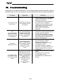
10.
Troubleshooting ................................................................... 140
11.
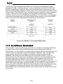
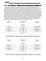
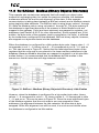
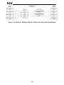
Appendix A: Database Endianness.................................... 141
11.1
11.2
11.3
11.4
11.5
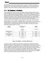
Ex: Modbus - Profibus .......................................................................143
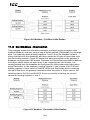
Ex: Modbus - DeviceNet ....................................................................144
Ex: BACnet - DeviceNet ....................................................................145
Ex: BACnet - Modbus (Analog Objects-Registers) ............................147
Ex: BACnet - Modbus (Binary Objects-Discretes) .............................148
12.
Appendix B: Status Information ......................................... 150
6
ICC
1. Introduction
Congratulations on your purchase of the ICC XLTR-1000 Multiprotocol RS-485
Communications Gateway. This gateway allows information to be transferred
seamlessly between various RS-485-based networks. In addition to the
supported fieldbus protocols, the gateway hosts a USB interface for configuring
the gateway via a PC.
Before using the gateway, please familiarize yourself with the product and be
sure to thoroughly read the instructions and precautions contained in this manual.
In addition, please make sure that this instruction manual is delivered to the end
user of the gateway, and keep this instruction manual in a safe place for future
reference or unit inspection.
For the latest information, support software and firmware releases, please visit
http://www.iccdesigns.com.
Before continuing, please take a moment to ensure that you have received all
materials shipped with your kit. These items are:
•
•
•
•
XLTR-1000 gateway in plastic housing
Documentation CD-ROM
DIN rail adapter with two pre-mounted screws
Four black rubber feet
Note that different gateway firmware versions may provide varying levels of
support for the various protocols. When using this manual, therefore, always
keep in mind that the firmware version indicated on your unit must be listed on
page 2 for all documented aspects to apply.
This manual will primarily be concerned with the gateway’s hardware
specifications, installation, wiring, configuration and operational characteristics.
To maximize the abilities of your new gateway, a working familiarity with this
manual will be required. This manual has been prepared for the gateway installer,
user, and maintenance personnel. With this in mind, use this manual to develop a
system familiarity before attempting to install or operate the gateway.
7
ICC
2. Features
Supported Protocols
The gateway currently provides support for the following fieldbus protocols:
•
A.O. Smith AIN Slave
•
A.O. Smith PDNP Master
•
BACnet MS/TP Client
•
BACnet MS/TP Server
•
TCS Basys Master
•
MSA Chillgard Monitor
•
DMX-512 Master
•
DMX-512 Slave
•
M-Bus (“Meter-Bus”) Master
•
Johnson Controls Metasys N2 Master
•
Johnson Controls Metasys N2 Slave
•
Modbus RTU Master
•
Modbus RTU Slave
•
Modbus RTU Sniffer
•
Siemens FLN Slave
•
Sullair Supervisor Network Master
•
Toshiba ASD Protocol Master
Note that any combination of these protocols may be configured on the gateway’s
“RS-485 A” and “RS-485 B” ports.
Supported Baud Rates
The gateway currently provides support for the following baud rates:
•
•
•
•
•
•
300
600
1200
2400
4800
9600
•
•
•
•
•
19200
38400
57600
76800
115200
Note that not all protocols support every baud rate listed above. Refer to section
9 for more information.
Field-Upgradeable
As new firmware becomes available, the gateway can be upgraded in the field by
the end-user. Refer to section 8.1 for more information.
USB Interface
The gateway can be connected to a PC via a USB mini type-B cable. This
simultaneously supplies power while providing the ability to configure the
8
ICC
gateway, monitor data, and update firmware on the device using the ICC
Gateway Configuration Utility. Refer to section 8.1 for more information.
Flexible Mounting Capabilities
The gateway includes all hardware for desktop, panel/wall and DIN-rail mounting
capabilities. Refer to section 6.1 for more information.
9
ICC
3. Gateway Concepts
The XLTR-1000 is a member of the Millennium Series communication gateways.
Members of this family are designed to provide a uniform interface, configuration
and application experience. This commonality reduces the user’s learning curve,
reducing commissioning time while simplifying support. All Millennium Series
gateways are configured using the ICC Gateway Configuration Utility. The XLTR1000 provides simultaneous support for two different communication protocols,
allowing complex interchanges of data between otherwise incompatible networks.
The heart of the Millennium Series concept is its internal database. The database
is a 4 KB, byte-wise addressable data array. The database allows data to be
routed from any supported network to any other supported network. Data may be
stored into the database in either big-endian style (meaning that if a 16-bit or 32bit value is stored in the database, the most significant byte will start at the lowest
address) or little-endian style (meaning that if a 16-bit or 32-bit value is stored in
the database, the least significant byte will start at the lowest address).
The other fundamental aspect of the Millennium Series is the concept of a
configurable “service object”. A service object is used for any master/client
protocol to describe what service (read or write) is to be requested on the
network. The gateway will cycle through the defined service objects in a roundrobin fashion; however, the gateway does implement a “write first” approach. This
means that the gateway will perform any outstanding write services before
resuming its round-robin, read request cycle.
Additionally, the database and service objects provide the added benefit of “data
mirroring”, whereby current copies of data values (populated by a service object)
are maintained locally within the gateway itself. This greatly reduces the requestto-response latency times on the various networks, as requests (read or write)
can be entirely serviced locally, thereby eliminating the time required to execute a
secondary transaction on a different network.
Regardless of their network representation, all data values are stored in the
gateway’s internal database as integer values (either 8-, 16- or 32-bits in length,
depending on the protocol and/or object configuration). This means that even if a
network variable is accessed by the gateway as a 32-bit floating-point number,
this native representation will always be converted to an equivalent integer
representation prior to being stored in the database. Once in the database, this
value will then be accessible to the network operating on the other port of the
gateway, which may then impose its own conversion process on the data. A
port’s conversion may be implicit (e.g. all Modbus holding registers are
interpreted by the protocol as 16-bit unsigned integers) or explicit (as configured
in a BACnet service object).
In order to facilitate the free scaling and conversion of native data values, a userconfigurable “multiplier” and “data type” exist for some network configurations. All
network values are scaled by a multiplier prior to being stored into the database
or after being retrieved from the database. The data type is used to determine
10
ICC
how many bytes are allocated for the value in the database and whether or not to
interpret the number as signed or unsigned upon retrieval from the database.
A typical use of the multiplier feature is to preserve the fractional components of
a network value for insertion into the database. For example, if the floating-point
value “3.19” is read by the gateway from a remote BACnet device, then we could
use a multiplier value of 0.01 to preserve all of the significant digits of this value:
the network representation (3.19) will be divided by the multiplier value (0.01) to
obtain a resultant value of 319, which will then be inserted into the database.
Similarly, when a value in the database corresponding to a specific service object
is changed (which therefore requires that this updated value be written to the
associated remote device on the network), the service object’s multiplier value
will first be multiplied by the database value in order to obtain the resultant
network value. For example, if 3000 is written to the database at a location
corresponding to a certain service object on the other port, and that service
object’s multiplier value is 0.1, then the database value (3000) will be multiplied
by the multiplier value (0.1) to obtain the resultant network value of 300.0, which
will then be written to the network as a native floating point value.
An appropriate data type should be selected based on the range of the network
data values. For example, if the value of an Analog Output on a remote BACnet
device can vary from –500 to 500, a 16-bit signed data type should be used. If
the value can only vary from 0 to 150, for example, an 8-bit unsigned data type
may be used. Care must be taken so that a signed data type is selected if
network data values can be negative. For example, if 0xFF is written to the
database at a location corresponding to a service object with an 8-bit unsigned
data type, the resultant network value will be 25510 (assuming a multiplier of 1).
However, if 0xFF is written to the database at a location corresponding to a
service object with an 8-bit signed data type, the resultant network value will be
−110 (again, assuming a multiplier of 1). It is also important to select a data type
large enough to represent the network data values. For example, if a value of 257
is read by the gateway from a remote device and the data type corresponding to
that service object is 8-bit unsigned, the value that actually will be stored is 1
(assuming a multiplier of 1). This is because the maximum value that can be
stored in 8-bits is 255. Any value higher than this therefore results in overflow.
The Millennium Series gateways also provide a powerful data-monitoring feature
that allows the user to view and edit the database in real time, as well as view the
status of service objects via the ICC Gateway Configuration Utility’s Monitor tab
when connected via USB to a PC.
When properly configured, the gateway will become essentially “transparent” on
the networks, and the various network devices can engage in seamless dialogs
with each other.
11
ICC
4. Precautions and Specifications
Rotating shafts and electrical equipment can be hazardous.
Installation, operation, and maintenance of the gateway shall be
performed by Qualified Personnel only.
Qualified Personnel shall be:
• Familiar with the construction and function of the gateway, the
equipment being driven, and the hazards involved.
• Trained and authorized to safely clear faults, ground and tag
circuits, energize and de-energize circuits in accordance with
established safety practices.
• Trained in the proper care and use of protective equipment in
accordance with established safety practices.
Installation of the gateway should conform to all applicable National
Electrical Code (NEC) Requirements For Electrical Installations, all
regulations of the Occupational Safety and Health
Administration, and any other applicable national, regional, or
industry codes and standards.
DO NOT install, operate, perform maintenance, or dispose of this
equipment until you have read and understood all of the following
product warnings and user directions. Failure to do so may result in
equipment damage, operator injury, or death.
4.1 Installation Precautions
•
Avoid installation in areas where vibration, heat, humidity, dust,
metal particles, or high levels of electrical noise (EMI) are
present.
• Do not install the gateway where it may be exposed to
flammable chemicals or gasses, water, solvents, or other fluids.
• Where applicable, always ground the gateway to prevent
electrical shock to personnel and to help reduce electrical noise.
Note: Conduit is not an acceptable ground.
• Follow all warnings and precautions and do not exceed
equipment ratings.
12
ICC
4.2 Maintenance Precautions
• Do Not attempt to disassemble, modify, or repair the gateway.
Contact your ICC sales representative for repair or service
information.
• If the gateway should emit smoke or an unusual odor or sound,
turn the power off immediately.
• The system should be inspected periodically for damaged or
improperly functioning parts, cleanliness, and to determine that
all connectors are tightened securely.
4.3 Inspection
Upon receipt, perform the following checks:
•
Inspect the unit for shipping damage.
•
Check for loose, broken, damaged or missing parts.
Report any discrepancies to your ICC sales representative.
4.4 Maintenance and Inspection Procedure
Preventive maintenance and inspection is required to maintain the gateway in its
optimal condition, and to ensure a long operational lifetime. Depending on usage
and operating conditions, perform a periodic inspection once every three to six
months.
Inspection Points
•
Check that there are no defects in any attached wire terminal crimp points.
Visually check that the crimp points are not scarred by overheating.
•
Visually check all wiring and cables for damage. Replace as necessary.
•
Clean off any accumulated dust and dirt.
•
If use of the interface is discontinued for extended periods of time, apply
power at least once every two years and confirm that the unit still functions
properly.
•
Do not perform hi-pot tests on the interface, as they may damage the unit.
Please pay close attention to all periodic inspection points and maintain a good
operating environment.
13
ICC
4.5 Storage
•
Store the device in a well-ventilated location (in its shipping carton, if
possible).
•
Avoid storage locations with extreme temperatures, high humidity, dust, or
metal particles.
4.6 Warranty
This gateway is covered under warranty by ICC, Inc. for a period of 12 months
from the date of installation, but not to exceed 18 months from the date of
shipment from the factory. For further warranty or service information, please
contact Industrial Control Communications, Inc. or your local distributor.
4.7 Disposal
•
Contact the local or state environmental agency in your area for details on
the proper disposal of electrical components and packaging.
•
Do not dispose of the unit via incineration.
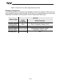
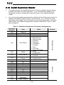
4.8 Environmental Specifications
Item
Specification
Operating Environment
Indoors, less than 1000m above sea level, do not
expose to direct sunlight or corrosive / explosive
gasses
Operating Temperature
-10 ∼ +50°C (+14 ∼ +122°F)
Storage Temperature
-40 ∼ +85°C (-40 ∼ +185°F)
Relative Humidity
20% ∼ 90% (without condensation)
Vibration
5.9m/s2 {0.6G} or less (10 ∼ 55Hz)
Grounding
Cooling Method
Non-isolated, referenced to power ground
Self-cooled
This device is lead-free / RoHS-compliant.
14
ICC
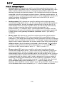
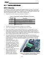
5. Gateway Overview
USB connector
“RS-485 A” terminal
block
“RS-485 A”
TX and RX LEDs
“RS-485 B”
TX and RX LEDs
Gateway status LED
Gateway Overview (Front)
Power terminals
“RS-485 B” terminals
Shield terminal
Gateway Overview (Back)
15
ICC
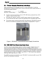
5.1 Power Supply Electrical Interface
When the gateway is not plugged into a PC via the USB cable, it must be
powered by an external power source. Ensure that the power supply adheres to
the following specifications:
Voltage rating ......................... 7 – 24VDC
Minimum Current rating .......... 50mA (@24VDC)
•
Typical current consumption of the XLTR-1000 when powered from a 24V
supply is approximately 15mA.
•
ICC offers an optional 120VAC/12VDC power supply (ICC part number
10755) that can be used to power the gateway from a standard wall outlet.
•
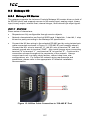
The power supply must be connected to the gateway’s “RS-485 B” terminal
block at terminals #5 (POWER) and #6 (GND) as highlighted in Figure 1.
Figure 1: “RS-485 B” Terminal Block Power Supply Connections
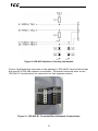
5.2 RS-485 Port Electrical Interface
In order to ensure appropriate network conditions (signal voltage levels, etc.)
when using the gateway’s RS-485 ports, some knowledge of the network
interface circuitry is required. Refer to Figure 2 for a simplified network schematic
of the RS-485 interface circuitry. Both the “RS-485 A” and “RS-485 B” ports have
4 terminals for four-wire communication. For two-wire communication, connect a
jumper wire between TB:1 (A / RXD+) and TB:3 (Y / TXD+) and a wire between
TB:2 (B / RXD-) and TB:4 (Z / TXD-).
The GND terminals (terminal #5 on port “RS-485 A” and terminal #6 on port “RS485 B”) are internally connected.
16
ICC
Figure 2: RS-485 Interface Circuitry Schematic
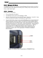
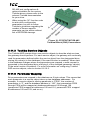
Figure 3 highlights the terminals on the gateway’s “RS-485 B” terminal block that
are specific to RS-485 network connections. Equivalent terminals exist on the
“RS-485 A” terminal block for connection to that separate subnet.
Figure 3: “RS-485 B” Terminal Block Network Connections
17
ICC
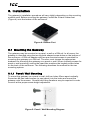
6. Installation
The gateway’s installation procedure will vary slightly depending on the mounting
method used. Before mounting the gateway, install the 4 black rubber feet
(Figure 4) onto the bottom of the enclosure.
Figure 4: Rubber Feet
6.1 Mounting the Gateway
The gateway may be mounted on a panel, a wall or a DIN rail. In all cases, the
gateway is mounted using the two keyhole-shaped screw holes on the bottom of
the enclosure. A DIN rail adapter with two pre-mounted screws is provided for
mounting the gateway on a DIN rail. The user must choose the appropriate
hardware for mounting the gateway on a panel or wall. When choosing screws for
panel or wall mounting, ensure the head size matches the keyhole screw holes
on the back of the enclosure. The following describes the method for the two
mounting options.
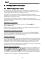
6.1.1 Panel / Wall Mounting
To mount the gateway on a panel or wall, drill two holes 25mm apart vertically.
Screw two #6 pan head screws (or equivalent) into the holes and mount the
gateway onto the screws. Several test-fitting iterations may be required in order
to arrive at the proper screw height adjustment.
Figure 5: Panel / Wall Mounting Diagram
18
ICC
6.1.2 DIN Rail Mounting
The DIN rail adapter (Figure 6) can clip onto 35mm and G-type rails. To mount
the gateway to a DIN rail, clip the DIN rail adapter onto the DIN rail and mount
the gateway on the screws (the screws should already be seated into the adapter
at the proper height). Refer to Figure 7, Figure 8, and Figure 9.
Figure 6: DIN Rail Adapter
Figure 7: DIN Rail Adapter Attachment
Figure 9: Example Installation
Figure 8: Unit with Attached
DIN Rail Adapter
19
ICC
6.2 Wiring Connections
Note that in order to power the unit, a power supply must also be installed. Refer
to section 5.1 for more information.
1.
Mount the unit via the desired method (refer to section 6.1).
2.
Connect the various networks to their respective plugs/terminal blocks.
Ensure that any wires are fully seated into their respective terminal blocks,
and route the network cables such that they are located well away from any
electrical noise sources, such as adjustable-speed drive input power or
motor wiring. Also take care to route all cables away from any sharp edges
or positions where they may be pinched.
3.
Take a moment to verify that the gateway and all network cables have
sufficient clearance from electrical noise sources such as drives, motors, or
power-carrying electrical wiring.
4.
Connect the power supply to the gateway’s “RS-485 B” terminal block on the
terminals labeled POWER and GND. Pay particular attention to the proper
polarity.
6.3 Grounding
Grounding is of particular importance for reliable, stable operation.
Communication system characteristics may vary from system to system,
depending on the system environment and grounding method used. The
gateway has two logic ground terminals (terminal #5 on port “RS-485 A” and
terminal #6 on port “RS-485 B”) that are internally connected. These ground
terminals serve as the ground reference for both power and RS-485
communication signals.
The gateway is also provided with a “Shield” terminal adjacent to the “RS-485 B”
terminal block. This shield terminal has no internal connection: its purpose is
simply to provide a cable shield chaining location between devices. The shield is
then typically connected to ground at one location only.
Please be sure to consider the following general points for making proper ground
connections:
Grounding method checkpoints
1. Make all ground connections such that no ground current flows through the
case or heatsink of a connected electrical device.
2. Do not connect the Shield terminal to a power ground or any other potential
noise-producing ground connection (such as a drive’s “E” terminal).
3. Do not make connections to unstable grounds (paint-coated screw heads,
grounds that are subjected to inductive noise, etc.)
20
ICC
7. LED Indicators
The gateway contains several different LED indicators, each of which conveys
important information about the status of the unit and connected networks. These
LEDs and their functions are summarized here.
7.1 Gateway Status
The gateway has one dichromatic LED to indicate the status of the device. On
startup, the LED blinks a startup sequence: Green, Red, Green, Red. Always
confirm this sequence upon powering the gateway to ensure the device is
functioning properly.
Solid green ............. The status LED lights solid green when the gateway has
power and is functioning normally.
Flashing green ........ The status LED flashes green when the gateway is
connected to a PC via a USB cable.
Flashing red ............ If a fatal error occurs, the status LED will flash a red error
code. The number of sequential blinks (followed by 2
seconds of OFF time) indicates the error code.
7.2 RS-485 Network Status LEDs
The gateway has one red and one green LED for each of the two RS-485 ports to
indicate the status of that RS-485 network.
Green (TX) LED ..... Lights when the gateway is transmitting data on that RS-485
port.
Red (RX) LED ........ Lights when the gateway is receiving data on that RS-485
port. Note that this does not indicate the validity of the data
with respect to a particular protocol: only that data exists and
is being detected. Also note that if a 2-wire RS-485 network
is in use, that the corresponding RX LED will light in
conjunction with the TX LED (as transmitting devices on 2wire RS-485 networks also receive their own transmissions).
21
ICC
8. Configuration Concepts
8.1 USB Configuration Utility
The gateway can be configured by a PC via a USB mini type-B cable. This
connection provides power to the device, so there is no need for any external
power supply while the gateway is attached to the PC.
The gateway is configured by the ICC Gateway Configuration Utility PC
application. For information on how to install the utility, refer to the ICC Gateway
Configuration Utility User’s Manual.
The following will briefly describe how to configure the gateway using the
configuration utility. For more information, refer to the ICC Gateway Configuration
Utility User’s Manual.
Manually Selecting a Device
Select the XLTR-1000 from the device menu: click Device→Select
Device→XLTR-1000.
Note that when a device is selected, the utility will then automatically attempt to
locate any connected devices of that type.
Automatically Connecting To a Device
If a device is already connected to the PC, you can click the Auto Connect
button and the utility will automatically select the correct device and upload the
current configuration from the connected device.
General Configuration
To configure the gateway, select the desired protocol, baud rate, parity, address,
timeout, and scan rate/response delay for both RS-485 ports, and configure any
objects associated with the designated protocols (refer to section 8.6 for more
information). For more information on configuring ports, refer to section 8.3.
Note that all numbers can be entered in not only decimal but also in hexadecimal
by including “0x” before the hexadecimal number.
Database Endianness Selection
Select the desired endianness for how data will be stored in the database: click
Device→Database Endianness→Big Endian to use big endian style or click
Device→Database Endianness→Little Endian to use little endian style. Note
that this is part of the configuration and therefore does not take effect until the
configuration is downloaded to the device. For more information on the database
endianness, refer to Appendix A: Database Endianness.
22
ICC
Loading a Configuration from an XML File
To load a configuration from an XML file stored on the PC, click File→Load
Configuration… (or click the Load Configuration button on the toolbar).
Saving a Configuration to an XML File
To save the configuration to an XML file on the PC, click File→Save
Configuration… (or click the Save Configuration button on the toolbar).
Downloading a Configuration to a Device
To download the configuration to the gateway, click Device→Download
Configuration To Device (or click the Download Configuration To Device
button on the toolbar).
Note that because there is a different driver firmware for each protocol, the
correct firmware may not be installed on the device corresponding to your
configuration. The utility may need to update the firmware on the device before
the configuration can be loaded.
Updating Firmware
To update firmware on the gateway, click Device→Update Firmware (or click
the Update Firmware button on the toolbar).
Note that if a newer version exists for the firmware installed on the device, a
message will be displayed in the Status box indicating an update is available.
Resetting the Device
To reset the gateway, click Device→Reset Device (or click the Reset Device
button on the toolbar).
Monitoring the Database
To monitor the gateway’s database in real time, select the Monitor tab. Data is
updated automatically to reflect the actual values in the database. Values can be
edited by double clicking the data in the database. The status of service objects
can also be added and viewed in this tab in the Status list. Section 8.4.2
describes how to view the status of a service object. For more information, refer
to the ICC Gateway Configuration Utility User’s Manual.
8.2 Timeout Configuration Tab
The gateway can be configured to perform a specific set of actions when network
communications are lost. This allows each address in the database to have its
own unique “fail-safe” condition in the event of network interruption. Support for
this feature varies depending on the protocol: refer to the protocol-specific
section of this manual for further information.
23
ICC
Note that this feature is only used with slave/server protocols. This is not the
same as the timeout value used for master/client protocols. For more information,
refer to section 8.3.
There are two separate elements that comprise the timeout configuration:
•
•
The timeout time
Timeout Object configuration
8.2.1 Timeout Time
The timeout time is the maximum number of milliseconds for a break in network
communications before a timeout will be triggered. This timeout setting is
configured at the protocol level as part of the port configuration, and used by the
protocol drivers themselves to determine abnormal loss-of-communications
conditions and, optionally, trigger a gateway-wide timeout processing event. If it is
not desired to have a certain protocol trigger a timeout processing event, then the
protocol’s timeout time may be set to 0 (the default value) to disable this feature.
Refer to section 8.3 for details.
8.2.2 Timeout Object Configuration
A timeout object is used by the gateway as part of the timeout processing to set
certain addresses of the database to “fail-safe” values. When a timeout event is
triggered by a protocol, the timeout objects are parsed and the configured 8-bit,
16-bit, or 32-bit value is written to the corresponding address(es). The following
describes the configurable fields of a timeout object:
Database Addr
This field is the starting address in the database where the first data element of
this timeout object will begin. Depending on the designated Data Type, the
maximum allowable database address is 4095, 4094, or 4092 for 8-bit, 16-bit, or
32-bit sized objects, respectively.
Data Type
This field selects the size and range of valid values for each data element in this
timeout object. For instance, selecting 16-bit unsigned allows for a range of
values between 0 and 65535, using 2 bytes in the database. Whereas selecting
16-bit signed allows for a range of values between -32768 and 32767, also using
2 bytes in the database. Select the desired data type from this dropdown.
Value
This is the “fail-safe” timeout value that every data element in this timeout object
will be automatically written to upon processing of a timeout event triggered by a
protocol.
24
ICC
Length
This field is the number of data elements for this timeout object. The total number
of bytes modified by this timeout object is determined by the length multiplied by
the number of bytes in the data type selected (1, 2 or 4).
8.3 Port Configuration Tabs Protocol Selection Group
This section describes each available field in the Protocol Selection group of the
port configuration tabs. Note that support of these fields will vary by protocol, and
that unsupported fields will automatically be made non-selectable within the
configuration utility.
Protocol
Select the desired protocol for the port.
Baud Rate
Select the network baud rate for the port.
Parity
Select the network parity for the port.
Address
Select the network address at which the gateway will reside.
Timeout
For master/client protocols, enter the request timeout in milliseconds. This setting
is the maximum amount of time that the gateway will wait for a response from a
remote device after sending a request.
For slave/server protocols, this value is the maximum amount of time the protocol
driver will wait in between received packets before triggering a timeout event (for
network loss detection). For further timeout processing details, refer to section
8.2.
Scan Rate / Response Delay
For master/client protocols, the scan rate is the number of milliseconds the
device will wait between sending requests. This is a useful feature for certain
devices or infrastructure components (such as radio modems) that may not be
capable of sustaining the maximum packet rates that the gateway is capable of
producing. The start time for this delay is taken with respect to the moment at
which the gateway is capable of sending the next packet (due to either reception
or timeout of the previous request). The default setting of 0 means that the
gateway will send its next request packet as soon as possible.
25
ICC
For slave/server protocols, the response delay is the number of milliseconds the
device will wait before responding to a request. This is a useful feature for
certain master devices or infrastructure components (such as radio modems) that
may require a given amount of time to place themselves into a “receiving mode”
where they are capable of listening for slave responses. The default setting of 0
means that the gateway will send its responses as soon as possible.
8.4 Service Object Configuration
A service object is used by the gateway to make requests on a network when a
master/client protocol is enabled. Each service object defines the services (read
or write) that should be performed on a range of network objects of a common
type. The data from read requests is mirrored in the database starting at a userdefined address (if a read function is enabled). When a value within that address
range in the database changes, a write request is generated on the network (if a
write function is enabled). Depending on the protocol selected, service objects
will vary slightly. Refer to section 8.6 for specific examples.
8.4.1 Description of Common Fields
This section contains general descriptions of the common service object fields,
regardless of which protocol is selected. Each protocol has its own additional
fields, as well as a more specific implementation of the common fields. These are
discussed in section 8.6.
Description
This field is a description of the service object. It is not used by the gateway, but
serves as a reference for the user.
Destination Address
This field is the network node address of the device that the gateway will send a
request to.
Type
This selects the object type to use in the service object. All objects in the service
object will be of this type.
Start Object
This field specifies the first instance number of the service object range.
Number of Objects
This field specifies the number of objects the service object contains in its range.
26
ICC
Database Address
This is the starting address in the gateway’s database that is used to mirror the
data on the network. The number of bytes allocated for the service object data is
determined by the data type and the number of objects in the service object.
Data Type
This field specifies how many bytes are used to store each object in the service
object. The data type also specifies whether the value should be treated as
signed or unsigned when converting it to a real number to send over the network.
Note that each data type has its own range limitations for what can be stored in
the database: 8 bits can store values up to 255, 16 bits can store values up to
65,535, and 32 bits can store values up to 4,294,967,295.
Multiplier
This field is the amount that associated network values are scaled by prior to
being stored into the database or after being retrieved from the database. Upon
retrieval from the database, the data is multiplied by the multiplier to produce a
network value. Similarly, network values are divided by the multiplier before being
stored into the database.
Note that the multiplier, coupled with the data type, imposes range limitations on
network data values. For example, if the data type is 8-bit and the multiplier is
0.5, then the network data can achieve a maximum value of only 127 (since 255
is the maximum value that can be stored in 8 bits in the database).
Function Codes
This field allows you to select which function code to use for a read or write. You
may also specify a read-only or a write-only service object by unchecking the
checkbox next to the write or the read function, respectively.
Note that some protocols only support one read and one write function code.
8.4.2 Viewing the Status of a Service Object
The gateway provides the user the ability to debug the configured service objects
while the device is running. When defining a service object, check the Reflect
Status checkbox and enter the database address to store the status information.
The status information is a 16-byte structure containing a transmission counter, a
receive counter, a receive error counter, the current status, and the last error of
the defined service object. This information is detailed in Appendix B: Status
Information. The data contained in the status information may be viewed over the
network on the other port of the gateway by mapping objects to the same
database address where the status information is stored.
Alternatively, the status can be viewed in the Monitor tab in the Status list of the
configuration utility. When a configuration that contains a service object status is
downloaded to the device, or uploaded from the device, that address is
27
ICC
automatically added into the Status list in the Monitor tab (status addresses can
also be added manually in the Monitor tab by typing the address and clicking
Add Status Address). This window will show the value of each of the counters
and a translation of the current status and last error. In addition, the counters can
be reset by selecting one or more entries in the Status list and clicking Reset
Counters. Status addresses can also be deleted by selecting one or more
entries in the Status list and clicking Delete Status Address, or all of the entries
can be deleted by clicking Delete All Status Addresses.
8.5 General Object Editing Options
The following editing options apply for all types of configuration objects including,
but not limited to, Connection Objects, Service Objects, Register Remap Objects,
Timeout Objects and BACnet Objects.
Creating an Object
To create an object, populate all the fields with valid values and click the Create
button.
Viewing an Object
Objects are listed in the object window located at the bottom of the configuration
utility. To view an object, select that object’s entry in the object window. This will
cause all of the object configuration fields to be populated with the object’s
current settings.
Updating an Object
To update an object, select the object’s entry in the object window, make any
required changes, and then click the Update button.
Copying an Object
To copy an object, select the entry you wish to copy in the object window, make
any required changes, and then click the Create button. This may be a useful
feature for situations in which many objects must be configured, but only a few
fields (such as the database address and type) are different.
Deleting an Object
To delete an object, select the entry you wish to delete in the object window and
click the Delete button. Note that this action cannot be undone.
Deleting all Objects
To delete all the objects in the object window, click the Delete All button. Note
that this action cannot be undone.
28
ICC
8.6 Protocol Configuration
The following section describes how to configure protocols on the gateway with
the configuration utility. As a rule, the two RS-485 ports on the gateway are
equivalent to each other. During configuration, it therefore makes no difference
whether port A or port B is assigned to each specific network in use. For more
details on how to use the configuration utility, refer to the ICC Gateway
Configuration Utility User’s Manual.
8.6.1 A.O. Smith AIN Slave
A.O. Smith AIN (Advanced Internal Network) Slave can be configured on either
RS-485 port by selecting AO Smith AIN Slave from the protocol dropdown
menu. The AIN Slave protocol uses service objects to define desired parameters
from the master to capture the values for and to write to. For more information on
service objects, refer to section 8.4. Each parameter in a service object is
mapped to 2 bytes in the database (the data size is fixed at 16-bit, as this is the
native data size of AIN parameters). For more information on parameter
mapping, refer to section 9.1.2.
8.6.1.1 Protocol Selection Group
Protocol
Select AO Smith AIN Slave from this dropdown menu.
Baud Rate
Select the desired network baud rate from this dropdown menu.
8.6.1.2 AIN Service Object Configuration
This section describes the configurable fields for an AIN service object. For more
information on AIN service object editing options, refer to section 8.5.
Description
This field is a description of the service object. It is not used on the gateway, but
serves as a reference for the user. Enter a string of up to 16 characters in length.
Block Num
This field indicates the block number that the desired parameters are located in.
Enter a value between 0 and 29 to target a specific block.
Start Param
This field defines the starting parameter number for a range of parameters
associated with this service object. Enter a value between 0 and 255.
29
ICC
Num Params
This field defines the number of parameters associated with this service object.
Enter a value between 1 and 255.
Database Addr
This field defines the database address where the first parameter of this service
object will be mapped. Enter a value between 0 and 4094. Note that the
configuration utility will not allow entry of a starting database address that will
cause the service object to run past the end of the database. The highest valid
database address, therefore, depends on the number of parameters to be
accessed.
Multiplier
This field is the amount that associated network values are scaled by prior to
being stored into the database or after being retrieved from the database. Upon
retrieval from the database, raw data is multiplied by the multiplier to produce a
network value (to be sent to the device). Similarly, network values (read from the
device) are divided by the multiplier before being stored into the database.
Note that the multiplier imposes range limitations on network data values. For
example, if the multiplier is 0.01, then the network data can achieve a maximum
value of only 655 (since 65535 is the maximum value that can be stored in 16 bits
in the database).
Read Enable
Check Read to enable reading (capturing the values of parameters from a
broadcast). All read-enabled service objects will be used to compare block and
parameter numbers for each master broadcast.
Write Enable
Check Write to enable writing (when values encompassed by this service object
change in the gateway’s database, these changes will be written to the master on
the next poll request).
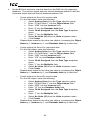
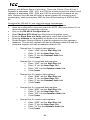
8.6.1.3 Configuration Example
This example will configure the gateway for end-to-end communication using AIN
slave and BACnet MS/TP server.
Say, for instance, we wish to communicate to an A.O. Smith water heater from a
building automation system (BAS) that uses BACnet MS/TP. We wish to monitor
the primary temperature, secondary temperature, and controlling temperature on
the water heater, located in block 0 at parameters 2, 3, and 5, respectively. To
control setpoints on the water heater, we can map the setpoint temperature and
setpoint differential located in block 0 at parameters 6 and 7, respectively.
Configure the “RS-485 A” port (BACnet server) using the above requirements
•
Connect the gateway to the PC via a USB mini type-B cable.
30
ICC
•
•
•
•
•
•
•
Open the configuration utility and select the XLTR-1000 (see section 8.1 for
more information on selecting a device).
Click on the RS-485 A Configuration tab.
Select BACnet MS/TP Server from the protocol dropdown menu.
Enter the Baud Rate settings to match that of the BAS.
Enter the Address at which the gateway will reside on the network.
Enter a Device Name, device Instance Number, and the Max Master for
the gateway.
Create BACnet objects to map the data from the gateway’s database to the
BAS. The monitor object data will start at database address 0 and the
command object data will start at database address 100.
o Create objects for temperature monitoring points
For the first object, enter the following:
•
Select Analog Input from the Type selection group.
•
Enter “Primary Temp” into the Object Name field.
•
Enter “0” into the Instance field.
•
Enter “0” into the Database Addr field.
•
Select 16-bit Unsigned from the Data Type dropdown
menu.
•
Enter “0.01” into the Multiplier field.
•
Select Celsius (62) from the Units dropdown menu.
•
Click Create.
Repeat these steps for the other two temperature points, increasing
the Instance by 1, and Database Addr by 2 each time.
o Create objects for the setpoints
Enter the following:
•
Select Analog Output from the Type selection group.
•
Enter “Setpoint Temp” into the Object Name field.
•
Enter “0” into the Instance field.
•
Enter “100” into the Database Addr field.
•
Select 16-bit Unsigned from the Data Type dropdown
menu.
•
Enter “0.01” into the Multiplier field.
•
Select Celsius (62) from the Units dropdown menu.
•
Click Create.
Repeat these steps for the setpoint differential, increasing the
Instance by 1, and Database Addr by 2.
Configure the “RS-485 B” port (AIN Slave) using the above requirements
•
Click on the RS-485 B Configuration tab.
•
Select AO Smith AIN Slave from the protocol dropdown menu.
•
Select the Baud Rate to match that of the network.
•
Create Service Objects to read and write the desired data.
o Create one service object to monitor the primary and secondary
temperatures.
•
Enter “0” into the Block Num field.
•
Enter “2” into the Start Param field.
•
Enter “2” into the Num Params field.
•
Enter “0” into the Database Addr field.
31
ICC
•
o
o
Uncheck the “write” function code check box (these are
monitor-only parameters, so there will be no need to write
to them)
•
Enter “5.12” for the Multiplier since these values are
scaled by 512 on the water heater and we would like to
preserve 2 decimal places.
•
Click Create.
Create one service object to monitor the controlling temperature.
•
Enter “0” into the Block Num field.
•
Enter “5” into the Start Param field.
•
Enter “1” into the Num Params field.
•
Enter “4” into the Database Addr field.
•
Uncheck the “write” function code check box (these are
monitor-only parameters, so there will be no need to write
to them)
•
Enter “5.12” for the Multiplier.
•
Click Create.
Create a final service object to control the setpoint values.
•
Enter “0” into the Block Num field.
•
Enter “6” into the Start Param field.
•
Enter “2” into the Num Params field.
•
Enter “100” into the Database Addr field.
•
Check both the “read” and “write” function code check
boxes.
•
Enter “5.12” for the Multiplier.
•
Click Create.
Finishing Up
•
Download the configuration to the gateway (see section 8.1 for more
information on downloading a configuration to a device).
•
Connect the gateway to the water heater and the BAS.
32
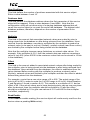
ICC
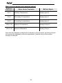
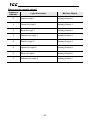
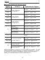
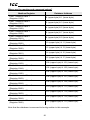
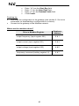
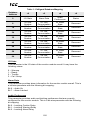
Where are the monitor and command values?
Database
Addresses
Water Heater Parameter
BACnet Object
0&1
Primary Temperature
Analog Input 0
2&3
Secondary Temperature
Analog Input 1
4&5
Controlling Temperature
Analog Input 2
100 & 101
Setpoint Temperature
Analog Output 0
102 & 103
Setpoint Differential
Analog Output 1
Note that the database endianness is arbitrary in this example, as both protocols
will access the database uniformly regardless of whether big or little endian
storage is selected.
33
ICC
8.6.2 A.O. Smith PDNP Master
A.O. Smith PDNP (Proprietary Device Network Protocol) Master can be
configured on either RS-485 port by selecting AO Smith PDNP Master from the
protocol dropdown menu. The PDNP Master protocol uses service objects to
make requests. For more information on service objects, refer to section 8.4.
Each parameter in a service object is mapped to 2 bytes in the database (the
data size is fixed at 16-bit, as this is the native data size of PDNP parameters).
For more information on parameter mapping, refer to section 9.2.2.
8.6.2.1 Protocol Selection Group
Protocol
Select AO Smith PDNP Master from this dropdown menu.
Timeout
This is the time in milliseconds that the device will wait for a response from a
device after sending a request.
Scan Rate
This is the time the device will wait between sending requests. This may be
useful if devices require additional time between requests. If no additional delay
time is needed, set this field to 0. For more information, refer to section 8.3.
8.6.2.2 PDNP Service Object Configuration
This section describes the configurable fields for a PDNP service object. For
more information on PDNP service object editing options, refer to section 8.5.
Description
This field is a description of the service object. It is not used on the gateway, but
serves as a reference for the user. Enter a string of up to 16 characters in length.
Dest Address
This field indicates the destination address of the device on the network that will
be accessed by this service object. Enter a value between 0 and 31 to target a
specific device.
Start Param
This field defines the starting parameter number for a range of parameters
associated with this service object. Enter a value between 0 and 126.
Num Params
This field defines the number of parameters associated with this service object.
Enter a value between 1 and 127.
34
ICC
Database Addr
This field defines the database address where the first parameter of this service
object will be mapped. Enter a value between 0 and 4094. Note that the
configuration utility will not allow entry of a starting database address that will
cause the service object to run past the end of the database. The highest valid
database address, therefore, depends on the number of parameters to be
accessed.
Multiplier
This field is the amount that associated network values are scaled by prior to
being stored into the database or after being retrieved from the database. Upon
retrieval from the database, raw data is multiplied by the multiplier to produce a
network value (to be sent to the device). Similarly, network values (read from the
device) are divided by the multiplier before being stored into the database.
Note that the multiplier imposes range limitations on network data values. For
example, if the multiplier is 0.01, then the network data can achieve a maximum
value of only 655 (since 65535 is the maximum value that can be stored in 16 bits
in the database).
Read Enable
Check Read to enable reading (the service object will continuously read from the
device unless a pending Write exists).
Write Enable
Check Write to enable writing (when values encompassed by this service object
change in the gateway’s database, these changes will be written down to the
targeted device).
Service Object Status
If it is desired to reflect the status of this service object, check the Reflect Status
checkbox and enter a database address between 0 and 4080 (0x0 – 0xFF0) at
which to store the status information. For more information on reflecting the
status of service objects, refer to section 8.4.2.
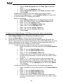
8.6.2.3 Configuration Example
This example will configure the gateway for end-to-end communication using
PDNP master and BACnet MS/TP server.
Say, for instance, we wish to communicate to an A.O. Smith boiler from a building
automation system (BAS) that uses BACnet MS/TP. We wish to monitor the inlet
temperature, outlet temperature, and tank temperature on the boiler, located at
parameters 0, 1, and 2 respectively. We also wish to control the operating
setpoint of the boiler located at parameter 3.
Configure the “RS-485 A” port (BACnet server) using the above requirements
•
Connect the gateway to the PC via a USB mini type-B cable.
35
ICC
•
•
•
•
•
•
•
Open the configuration utility and select the XLTR-1000 (see section 8.1 for
more information on selecting a device).
Click on the RS-485 A Configuration tab.
Select BACnet MS/TP Server from the protocol dropdown menu.
Enter the Baud Rate settings to match that of the BAS.
Enter the Address at which the gateway will reside on the network.
Enter a Device Name, device Instance Number, and the Max Master for
the gateway.
Create BACnet objects to map the data from the gateway’s database to the
BAS. The monitor object data will start at database address 0 and the
command object data will start at database address 100.
o Create objects for temperature monitoring points
For the first object, enter the following:
•
Select Analog Input from the Type selection group.
•
Enter “Inlet Temp” into the Object Name field.
•
Enter “0” into the Instance field.
•
Enter “0” into the Database Addr field.
•
Select 16-bit Unsigned from the Data Type dropdown
menu.
•
Enter “0.01” into the Multiplier field.
•
Select Celsius (62) from the Units dropdown menu.
•
Click Create.
Repeat these steps for the other two temperature points, increasing
the Instance by 1, and Database Addr by 2 each time.
o Create objects for the opterating setpoint
Enter the following:
•
Select Analog Output from the Type selection group.
•
Enter “Op Setpoint” into the Object Name field.
•
Enter “0” into the Instance field.
•
Enter “100” into the Database Addr field.
•
Select 16-bit Unsigned from the Data Type dropdown
menu.
•
Enter “0.01” into the Multiplier field.
•
Select Celsius (62) from the Units dropdown menu.
•
Click Create.
Configure the “RS-485 B” port (PDNP Master) using the above requirements
•
Click on the RS-485 B Configuration tab.
•
Select AO Smith PDNP Master from the protocol dropdown menu.
•
Create Service Objects to read and write the desired data.
o Create one service object to monitor the temperatures.
•
Enter the address of the boiler into the Dest Address field.
•
Enter “0” into the Start Param field.
•
Enter “3” into the Num Params field.
•
Enter “0” into the Database Addr field.
•
Uncheck the “write” function code check box (these are
monitor-only parameters, so there will be no need to write
to them)
36
ICC
•
o
Enter “5.12” for the Multiplier since these values are
scaled by 512 on the boiler and we would like to preserve
2 decimal places.
•
Click Create.
Create a service object to control the operating setpoint.
•
Enter the address of the boiler into the Dest Address field.
•
Enter “3” into the Start Param field.
•
Enter “1” into the Num Params field.
•
Enter “100” into the Database Addr field.
•
Check both the “read” and “write” function code check
boxes.
•
Enter “5.12” for the Multiplier.
•
Click Create.
Finishing Up
•
Download the configuration to the gateway (see section 8.1 for more
information on downloading a configuration to a device).
•
Connect the gateway to the boiler and the BAS.
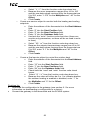
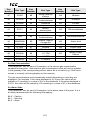
Where are the monitor and command values?
Database
Addresses
Boiler Parameter
BACnet Object
0&1
Inlet Temperature
Analog Input 0
2&3
Outlet Temperature
Analog Input 1
4&5
Tank Temperature
Analog Input 2
100 & 101
Operating Setpoint
Analog Output 0
Note that the database endianness is arbitrary in this example, as both protocols
will access the database uniformly regardless of whether big or little endian
storage is selected.
37
ICC
8.6.3 BACnet MS/TP Client
BACnet MS/TP Client can be configured on either RS-485 port by selecting
BACnet MS/TP Client from the protocol dropdown menu. The gateway can read
and write the present value property of BACnet objects hosted by other devices
on the network. This behavior is defined by configuring BACnet service objects.
For more information on service objects, refer to section 8.4. Whenever the
BACnet MS/TP client driver is enabled, the BACnet device object is always
present and must be properly configured. Note that BACnet MS/TP (client or
server) may only be enabled on one port of the gateway. This section will discuss
how to configure the BACnet MS/TP client.
8.6.3.1 Protocol Selection Group
This section describes the fields that must be configured on the RS-485 port.
Protocol
Select BACnet MS/TP Client from this dropdown menu.
Baud Rate
Select the network baud rate from this dropdown menu.
Address
This field is the node address that the gateway will reside at on the network.
Enter a value between 0 and 127.
Scan Rate
This is the time the device will wait between sending requests. This may be
useful if BACnet devices that the gateway is communicating with require
additional time between requests. If no additional time is required, set this field to
0.
8.6.3.2 Device Object Configuration Group
The Device Object Configuration group contains several fields that must be
appropriately set for each device residing on a BACnet network.
Device Name
This field is the BACnet Device Object’s name. The device name must be unique
across the entire BACnet network. Enter a string of between 1 and 16 characters
in length.
Instance Number
This field is the BACnet Device Object’s instance number. The instance number
must be unique across the entire BACnet network. Enter a value between 0 and
4194302 (0x0 – 0x3FFFFE).
38
ICC
Max Master
This field is the highest allowable address for MS/TP master nodes on the
network. Any address higher than this will not receive the token from the
gateway. Enter a value between 0 and 127. Note that this value must be greater
than or equal to the configured Address for the gateway. If the highest address
on the network is unknown, set this field to 127.
Configuration tip: The Address and Max Master fields greatly affect network
performance. For best results, set all device addresses consecutively, starting
with address 0, ending with a device with a configurable Max Master field at the
highest address. Then set that device’s Max Master field to its network address.
This will prevent any unnecessary poll for master packets on the network and
thereby maximize efficiency.
8.6.3.3 BACnet Service Object Configuration
The following describes the configurable fields for a BACnet service object. For
more information on BACnet service object editing options, refer to section 8.5.
Type
The radio buttons in this group select the BACnet object type. Choose from
Analog Input, Analog Output, Analog Value, Binary Input, Binary Output, or
Binary Value.
Description
This field is a description of the service object. It is not used on the gateway, but
serves as a reference for the user. Enter a string of between 1 and 16 characters
in length.
Dest Dev Inst (“Destination Device Instance”)
This field is the destination device instance of the BACnet device the gateway
should send requests to for this service object. Enter a value between 0 and
4194302 (0x0 – 0x3FFFFE).
Note that the gateway uses this value for dynamic device binding to determine
the address of the destination device. If the destination device does not support
dynamic device binding, then static device binding must be used. For more
information on device binding, refer to section 9.3.2.3.
Use Static Device Binding
This checkbox is used to manually define the destination device network address.
This feature must be used for all MS/TP slave devices, and for any MS/TP
master devices that do not support dynamic device binding. For more
information on device binding, refer to section 9.3.2.3.
39
ICC
Dest Address
Note that this field is available only when the Use Static Device Binding
checkbox is checked. This field is used to manually define the address of the
BACnet device that the gateway should target for this service object. Enter a
value between 0 and 127.
Start Inst
This field is the starting instance number for a range of BACnet objects for this
service object. Enter a value between 0 and 4194302 (0x0 – 0x3FFFFE).
Num Insts
This field is the number of BACnet objects in this service object. Enter a value of
1 or more.
Database Addr
This field is the database address where the first BACnet object of this service
object will be mapped. Enter a value between 0 and 4095 (0x0 – 0xFFF).
Note that the configuration utility will not allow entry of a starting database
address that will cause the service object to run past the end of the database.
The highest valid database address, therefore, will depend on the targeted data
type, as well as the number of items to be accessed.
Data Type
Applies to analog objects only. This field specifies how many bytes are used to
store present value data for each BACnet object in this service object, as well as
whether the value should be treated as signed or unsigned when converted to a
real number for transmission over the network. Select the desired data type from
this dropdown menu.
Note that each data type has its own range limitations: 8-bit can have values up
to 255, 16-bit can have values up to 65,535, and 32-bit can have values up to
4,294,967,295.
Multiplier
Applies to analog objects only. This field is the amount that associated network
values are scaled by prior to being stored into the database or after being
retrieved from the database. Upon retrieval from the database, the data is
multiplied by the multiplier to produce a network value. Similarly, the network
values are divided by the multiplier before being stored into the database.
Note that the multiplier, coupled with the data type, imposes range limitations on
the network data value. For example, if the data type is 8-bit and the multiplier is
0.5, then the network data can have values only up to 127 (since 255 is the
maximum value that can be stored in 8 bits).
40
ICC
Read Enable and Function Code Selection
Check Read to enable reading (the service object will continuously read from the
remote device unless a pending Write exists). When reads are enabled, the
desired read Function Code can be selected in the drop-down box.
Write Enable and Function Code Selection
Does not apply to input objects. Check Write to enable writing (when values
encompassed by this service object change in the gateway’s database, these
changes will be written down to the targeted remote device). When writes are
enabled, the desired write Function Code can be selected in the drop-down box.
Priority
This field is used to specify the priority associated with writes for this service
object. Select the desired priority from the dropdown menu.
Service Object Status
If it is desired to reflect the status of this service object, check the Reflect Status
checkbox and enter a database address between 0 and 4080 (0x0 – 0xFF0) at
which to store the status information. For more information on reflecting the
status of service objects, refer to section 8.4.2.
8.6.3.4 Configuration Example
This example will configure the gateway for end-to-end communication using
BACnet MS/TP client and Modbus RTU slave.
Say, for instance, we wish to communicate to an adjustable-speed drive that
supports BACnet MS/TP from a PLC that supports Modbus RTU. We wish to
monitor the output frequency, output current, and output voltage of the drive,
located at analog input objects 1, 2 and 3, with multipliers of 0.01, 0.01, and 0.1
respectively. We’d also like to monitor the running, forward/stop, and reverse/stop
bits, located at binary input objects 1, 2 and 3, respectively. To run the drive, we
need to be able to command the frequency command at analog output object 2
with a multiplier of 0.01, the command forward/stop bit at binary output object 2,
and command reverse/stop bit at binary output object 3.
Configure the “RS-485 A” port (Modbus slave) using the above requirements
•
Connect the gateway to the PC via a USB mini type-B cable.
•
Open the configuration utility and select the XLTR-1000 (see section 8.1 for
more information on selecting a device).
•
Click on the RS-485 A Configuration tab.
•
Select Modbus RTU Slave from the protocol dropdown menu.
•
Enter the Baud Rate and Parity settings to match that of the PLC.
•
Enter the slave address that your PLC is configured to communicate with
into the Address field.
•
The default mapping of the gateway’s database into the Modbus register
space will be used, so no register remap objects need to be created.
41
ICC
Configure the “RS-485 B” port (BACnet client) using the above requirements
•
Click on the RS-485 B Configuration tab.
•
Select BACnet MS/TP Client from the protocol dropdown menu.
•
Enter the Baud Rate settings to match that of the drive.
•
Enter the Address for the gateway to reside at on the network.
•
Enter a Device Name, device Instance Number, and the Max Master for
the gateway.
•
Create Service Objects to read and write the desired BACnet objects:
o We can create one service object to monitor the output frequency
and output current since they are the same type and have the same
multiplier value.
•
Select Analog Input from the Type selection group.
•
Enter the device instance of the drive into the Dest Dev
Inst field.
•
Enter “1” into the Start Inst field.
•
Enter “2” into the Num Insts field.
•
Enter “0” into the Database Addr field.
•
Select 32-bit Unsigned from the Data Type dropdown
menu.
•
Enter “0.01” into the Multiplier field.
•
Click Create.
o
Since the output voltage has a different multiplier than the other two
analog inputs, it must be defined as a separate service object.
•
Select Analog Input from the Type selection group.
•
Enter the device instance of the drive into the Dest Dev
Inst field.
•
Enter “3” into the Start Inst field.
•
Enter “1” into the Num Insts field.
•
Enter “8” into the Database Addr field.
•
Select 32-bit Unsigned from the Data Type dropdown
menu.
•
Enter “0.1” into the Multiplier field.
•
Click Create.
o
Now we must create a service object to monitor the running,
forward/stop, and reverse/stop bits.
•
Select Binary Input from the Type selection group.
•
Enter the device instance of the drive into the Dest Dev
Inst field.
•
Enter “1” into the Start Inst field.
•
Enter “3” into the Num Insts field.
•
Enter “12” into the Database Addr field.
•
Click Create.
o
To command the frequency command, we must create a service
object for that analog output.
•
Select Analog Output from the Type selection group.
42
ICC
•
•
•
•
•
•
•
o
Enter the device instance of the drive into the Dest Dev
Inst field.
Enter “2” into the Start Inst field.
Enter “1” into the Num Insts field.
Enter “16” into the Database Addr field.
Select 32-bit Unsigned from the Data Type dropdown
menu.
Enter “0.01” into the Multiplier field.
Click Create.
To command the forward/stop and reverse/stop command bits, one
last service object must be created.
•
Select Binary Output from the Type selection group.
•
Enter the device instance of the drive into the Dest Dev
Inst field.
•
Enter “2” into the Start Inst field.
•
Enter “2” into the Num Insts field.
•
Enter “20” into the Database Addr field.
•
Click Create.
Finishing Up
•
Download the configuration to the gateway (see section 8.1 for more
information on downloading a configuration to a device).
•
Connect to the gateway with your PLC.
43
ICC
Where are the monitor and command values?
Database
Address
BACnet Object
Modbus Discrete / Register
Register 1 – lower 16 bits
0&1
Output Frequency
(Analog Input 1)
2&3
Register 2 – upper 16 bits
Register 3 – lower 16 bits
4&5
Output Current
(Analog Input 2)
6&7
Register 4 – upper 16 bits
Register 5 – lower 16 bits
8&9
Output Voltage
(Analog Input 3)
10 & 11
12
Register 6 – upper 16 bits
Running
(Binary Input 1)
Discrete 97 / Register 7 – bit 0
Forward/Stop
(Binary Input 2)
Discrete 98 / Register 7 – bit 1
Reverse/Stop
(Binary Input 3)
Discrete 99 / Register 7 – bit 2
13..15
Unused
Register 9 – Lower 16 bits
16 & 17
Frequency Command
(Analog Output 2)
18 & 19
Register 10 – Upper 16 bits
Command Forward/Stop
(Binary Output 2)
Discrete 161 / Register 11 – bit 0
Command Reverse/Stop
(Binary Output 3)
Discrete 162 / Register 11 – bit 1
20
Note that the database is assumed to be little endian in this example. Also note
that the bit-access variables (Running, Command Forward/Stop, etc.) can be
simultaneously accessed from the Modbus network as either bits within a
register, or as individual discretes (refer to section 9.9.2.3).
44
ICC
8.6.4 BACnet MS/TP Server
BACnet MS/TP Server can be configured on either RS-485 port by selecting
BACnet MS/TP Server from the protocol dropdown menu. The BACnet MS/TP
server can host a wide variety of user-defined BACnet objects. Whenever the
BACnet MS/TP server is enabled, the BACnet device object is always present
and must be properly configured. Note that BACnet MS/TP (client or server) may
only be enabled on one port of the gateway. This section will discuss how to
configure the BACnet MS/TP server.
8.6.4.1 Protocol Selection Group
This section describes the fields that must be configured on the RS-485 port.
Protocol
Select BACnet MS/TP Server from this dropdown menu.
Baud Rate
Select the network baud rate from this dropdown menu.
Address
This field is the node address that the gateway will reside at on the network.
Enter a value between 0 and 127.
8.6.4.2 Device Object Configuration Group
The Device Object Configuration group contains several fields that must be
appropriately set for each device residing on a BACnet network.
Device Name
This field is the BACnet Device Object’s name. The device name must be unique
across the entire BACnet network. Enter a string of between 1 and 16 characters
in length.
Instance Number
This field is the BACnet Device Object’s instance number. The instance number
must be unique across the entire BACnet network. Enter a value between 0 and
4194302 (0x0 – 0x3FFFFE).
Max Master
This field is the highest allowable address for master nodes on the network. Any
address higher than this will not receive the token from the gateway. Enter a
value between 0 and 127. Note that this value must be greater than or equal to
the configured Address for the gateway. If the highest address on the network is
unknown, set this field to 127.
45
ICC
Configuration tip: The Address and Max Master fields greatly affect network
performance. For best results, set all device addresses consecutively, starting
with address 0, ending with a device with a configurable Max Master field at the
highest address. Then set that device’s Max Master field to its address. This will
prevent any unnecessary poll for master packets on the network and thereby
maximize efficiency.
8.6.4.3 BACnet Object Common Configurable Fields
This section describes the common configurable fields for all BACnet objects. For
more information on BACnet object editing options, refer to section 8.5.
Type
The radio buttons in this group select the BACnet object type. Choose from
Analog Input, Analog Output, Analog Value, Binary Input, Binary Output, or
Binary Value.
Object Name
This field is the name of the BACnet object. Enter a string of between 1 and 16
characters in length. All object names must be unique within the gateway.
Instance
This field is the BACnet Object’s instance number. Enter a value between 0 and
4194302 (0x0 – 0x3FFFFE).
Database Addr
This field is the database address where the BACnet object’s present value will
reside. Enter a value between 0 and 4095 (0x0 – 0xFFF).
A note for analog objects: Depending on the designated Data Type, the
maximum allowable database address is 4095, 4094, or 4092 for 8-bit, 16-bit, or
32-bit sized objects, respectively.
Multiplier
Applies to analog objects only. This field is the amount that associated network
values are scaled by prior to being stored into the database or after being
retrieved from the database. Upon retrieval from the database, the data is
multiplied by the multiplier to produce a network value. Similarly, the network
values are divided by the multiplier before being stored into the database.
Note that the multiplier, coupled with the data type, imposes range limitations on
the network data value. For example, if the data type is 8-bit and the multiplier is
0.5, then the network data can have values only up to 127 (since 255 is the
maximum value that can be stored in 8 bits).
46
ICC
Units
Applies to analog objects only. Select the desired units from this dropdown
menu. If the desired units are not available in the dropdown menu, select Other
Units and enter the enumerated value (as defined by the BACnet Specification)
in the Unit Value field.
Bitmask
Applies to binary objects only. This 8-bit field specifies which bit(s) in the byte
designated by the Database Addr that the binary object will map to. This allows
up to 8 binary objects to be simultaneously assigned to one database address
(each binary object mapping to a single bit of that byte in the database). It is
possible to map binary objects to multiple bits within the designated database
location. Such a configuration allows (for example) the modification of multiple
selected database bits via a single binary output.
The effect of the Bitmask field when writing: When the present value property of
a binary output object or binary value object is set to “active” by a BACnet client,
then the bit(s) in the designated Database Addr indicated by a “1” in the bitmask
are set. Similarly, when the present value property of the object is set to
“inactive”, then the bit(s) in the designated Database Addr indicated by a “1” in
the bitmask are cleared. For binary output objects, this setting/clearing behavior
is reversed if the object’s Polarity is set to “Reversed”.
The effect of the Bitmask field when reading: When the present value property
of a binary object is read by a BACnet client, the Bitmask is used to determine
the active/inactive state of the object by inspecting the value in the designated
database address at the bit location(s) indicated in the Bitmask. If all of the bit
locations at the designated database address indicated by a “1” in the Bitmask
are set, then the object’s state will be returned as “active”. Else, the object’s
state will be returned as “inactive”. For binary input and binary output objects, the
resultant state is reversed just prior to being placed on the network if the object’s
Polarity is set to “Reversed”.
Active Text
Applies to binary objects only. This field specifies the description of the object’s
“active” state. Enter a string of up to 8 characters in length. This field is optional
and may be left blank.
Inactive Text
Applies to binary objects only. This field specifies the description of the object’s
“inactive” state. Enter a string of up to 8 characters in length. This field is
optional and may be left blank.
Polarity
Applies to binary input and binary output objects only. This field indicates the
relationship between the physical state of the object (as stored in the gateway’s
database) and the logical state represented by the object’s present value
47
ICC
property. If the physical state is active high, select Normal from this dropdown
menu. If the physical state is active low, select Reverse from this dropdown
menu. For further detail, refer to the Bitmask behavioral description above.
Data Type
Applies to analog objects only. This field specifies how many bytes are allocated
for the present value data, as well as whether the value should be treated as
signed or unsigned when converting it to a real number to send over the network.
Select the desired data type from this dropdown menu.
Note that each data type has its own range limitations: 8-bit data types can have
values up to 255, 16-bit data types can have values up to 65,535, and 32-bit data
types can have values up to 4,294,967,295.
Relinquish Def
This field is the default value to be used for an object’s present value property
when all command priority values in the object’s priority array are NULL. Note
that this property only exists for those objects that implement a priority array
(analog output, analog value, binary output and binary value objects).
8.6.4.4 Configuration Example
This example will configure one port of the gateway (port A) for communication
using the BACnet MS/TP server driver. This example will only detail the
configuration of the BACnet server driver and related objects, with the goal of
mapping data from the BACnet MS/TP network into the gateway’s database.
Once this data is mapped into the gateway’s database, it is then accessible for
reading and writing via any other supported network connected to the other
gateway port (port B).
Assume that we have a building automation system (BAS) that can act as a
BACnet MS/TP client connected to the gateway’s “RS-485 A” port. The BAS
exchanges information (through the gateway) with different floors of a building.
There are 3 floors; floor #1 has 3 analog values at instances 1000, 1001, and
1002 for monitoring the floor status and 3 analog values at instances 1003, 1004,
and 1005 for executing commands on the floor. Similarly, floors #2 and #3 have
the same analog values for monitoring and commanding starting at instance 2000
for floor #2, and starting at instance 3000 for floor #3.
Configure the “RS-485 A” port using the above requirements
•
Connect the gateway to the PC via a USB mini type-B cable.
•
Open the configuration utility and select the XLTR-1000 (see section 8.1 for
more information on selecting a device).
•
Click on the RS-485 A Configuration tab.
•
Select BACnet MS/TP Server from the protocol dropdown menu.
•
Enter the Baud Rate settings to match that of the BAS.
•
Enter the Address at which the gateway will reside on the network.
•
Enter a Device Name, device Instance Number, and the Max Master for
the gateway.
48
ICC
•
Create BACnet objects to map the data from the BAS into the gateway’s
database. The monitor object data will start at database address 0 and the
command object data will start at database address 100.
o
Create objects for floor #1’s monitor data
For the first object, enter the following:
•
Select Analog Value from the Type selection group.
•
Enter “F1 Mon Data 1” into the Object Name field.
•
Enter “1000” into the Instance field.
•
Enter “0” into the Database Addr field.
•
Select 32-bit Unsigned from the Data Type dropdown
menu.
•
Enter “1” into the Multiplier field.
•
Select No Units (95) from the Units dropdown menu.
•
Click Create.
Repeat these steps for the other two objects, increasing the Object
Name by 1, Instance by 1, and Database Addr by 4 each time.
o
Create objects for floor #1’s command data
For the first object, enter the following:
•
Select Analog Value from the Type selection group.
•
Enter “F1 Cmd Data 1” into the Object Name field.
•
Enter “1003” into the Instance field.
•
Enter “100” into the Database Addr field.
•
Select 32-bit Unsigned from the Data Type dropdown
menu.
•
Enter “1” into the Multiplier field.
•
Select No Units (95) from the Units dropdown menu.
•
Click Create.
Repeat these steps for the other two objects, increasing the Object
Name by 1, Instance by 1, and Database Addr by 4 each time.
o
Create objects for floor #2’s monitor data
For the first object, enter the following:
•
Select Analog Value from the Type selection group.
•
Enter “F2 Mon Data 1” into the Object Name field.
•
Enter “2000” into the Instance field.
•
Enter “12” into the Database Addr field.
•
Select 32-bit Unsigned from the Data Type dropdown
menu.
•
Enter “1” into the Multiplier field.
•
Select No Units (95) from the Units dropdown menu.
•
Click Create.
Repeat these steps for the other two objects, increasing the Object
Name by 1, Instance by 1, and Database Addr by 4 each time.
49
ICC
o
Create objects for floor #2’s command data
For the first object, enter the following:
•
Select Analog Value from the Type selection group.
•
Enter “F2 Cmd Data 1” into the Object Name field.
•
Enter “2003” into the Instance field.
•
Enter “112” into the Database Addr field.
•
Select 32-bit Unsigned from the Data Type dropdown
menu.
•
Enter “1” into the Multiplier field.
•
Select No Units (95) from the Units dropdown menu.
•
Click Create.
Repeat these steps for the other two objects, increasing the Object
Name by 1, Instance by 1, and Database Addr by 4 each time.
o
Create objects for floor #3’s monitor data
For the first object, enter the following:
•
Select Analog Value from the Type selection group.
•
Enter “F3 Mon Data 1” into the Object Name field.
•
Enter “3000” into the Instance field.
•
Enter “24” into the Database Addr field.
•
Select 32-bit Unsigned from the Data Type dropdown
menu.
•
Enter “1” into the Multiplier field.
•
Select No Units (95) from the Units dropdown menu.
•
Click Create.
Repeat these steps for the other two objects, increasing the Object
Name by 1, Instance by 1, and Database Addr by 4 each time.
o
Create objects for floor #3’s command data:
For the first object, enter the following:
•
Select Analog Value from the Type selection group.
•
Enter “F3 Cmd Data 1” into the Object Name field.
•
Enter “3003” into the Instance field.
•
Enter “124” into the Database Addr field.
•
Select 32-bit Unsigned from the Data Type dropdown
menu.
•
Enter “1” into the Multiplier field.
•
Select No Units (95) from the Units dropdown menu.
•
Click Create.
Repeat these steps for the other two objects, increasing the Object
Name by 1, Instance by 1, and Database Addr by 4 each time.
Finishing Up
•
Configure the “RS-485 B” port for the other protocol to be used in accessing
the floors of the building.
•
Download the configuration to the gateway (see section 8.1 for more
information on downloading a configuration to a device).
50
ICC
Where are the monitor and command values?
BACnet Object
Database Addresses
Floor #1 Monitor Data 1 (AV1000)
0 (upper byte)..3(lower byte)
Floor #1 Monitor Data 2 (AV1001)
4 (upper byte)..7(lower byte)
Floor #1 Monitor Data 3 (AV1002)
8 (upper byte)..11(lower byte)
Floor #2 Monitor Data 1 (AV2000)
12 (upper byte)..15(lower byte)
Floor #2 Monitor Data 2 (AV2001)
16 (upper byte)..19(lower byte)
Floor #2 Monitor Data 3 (AV2002)
20 (upper byte)..23(lower byte)
Floor #3 Monitor Data 1 (AV3000)
24 (upper byte)..27(lower byte)
Floor #3 Monitor Data 2 (AV3001)
28 (upper byte)..31(lower byte)
Floor #3 Monitor Data 3 (AV3002)
32 (upper byte)..35(lower byte)
Floor #1 Command Data 1 (AV1003)
100 (upper byte)..103(lower byte)
Floor #1 Command Data 2 (AV1004)
104 (upper byte)..107(lower byte)
Floor #1 Command Data 3 (AV1005)
108 (upper byte)..111(lower byte)
Floor #2 Command Data 1 (AV2003)
112 (upper byte)..115(lower byte)
Floor #2 Command Data 2 (AV2004)
116 (upper byte)..119(lower byte)
Floor #2 Command Data 3 (AV2005)
120 (upper byte)..123(lower byte)
Floor #3 Command Data 1 (AV3003)
124 (upper byte)..127(lower byte)
Floor #3 Command Data 2 (AV3004)
128 (upper byte)..131(lower byte)
Floor #3 Command Data 3 (AV3005)
132 (upper byte)..135(lower byte)
Note that the database is assumed to be big endian in this example.
51
ICC
8.6.5 TCS Basys Master
TCS Basys Master can be configured on either RS-485 port by selecting Basys
Master from the protocol dropdown menu. The TCS Basys Master protocol uses
service objects to make requests. For more information on service objects, refer
to section 8.4. Each position in a service object is mapped to 2 bytes in the
database (the data size is fixed at 16-bit, as this is the native data size of TCS
Basys data). For more information on TCS Basys service objects, refer to
section 9.4.2.
8.6.5.1 Protocol Selection Group
Protocol
Select Basys Master from this dropdown menu.
Baud Rate
Select the desired network baud rate from this dropdown menu.
Timeout
This is the time in milliseconds that the device will wait for a response from a
drive after sending a request.
Scan Rate
This is the time the device will wait between sending requests. This may be
useful if drives require additional time between requests. If no additional delay
time is needed, set this field to 0. For more information, refer to section 8.3.
8.6.5.2 TCS Basys Service Object Configuration
This section describes the configurable fields for a TCS Basys service object. For
more information on TCS Basys service object editing options, refer to section
8.5.
Description
This field is a description of the service object. It is not used on the gateway, but
serves as a reference for the user. Enter a string of up to 16 characters in length.
Dest Address
This field indicates the destination address of the target device on the network
that will be accessed by this service object. Enter a value between 0 and 255.
Start Position
This field defines the starting position number for a given function code. Enter a
value between 0 and 15.
52
ICC
Num Positions
This field defines the number of positions associated with this service object.
Enter a value between 1 and 16.
Database Addr
This field defines the database address where the first parameter of this service
object will be mapped. Enter a value between 0 and 4094. Note that the
configuration utility will not allow entry of a starting database address that will
cause the service object to run past the end of the database. The highest valid
database address, therefore, depends on the number of parameters to be
accessed.
Multiplier
This field is the amount that associated network values are scaled by prior to
being stored into the database or after being retrieved from the database. Upon
retrieval from the database, raw data is multiplied by the multiplier to produce a
network value (to be sent to a drive). Similarly, network values (read from a drive)
are divided by the multiplier before being stored into the database.
Note that the multiplier imposes range limitations on network data values. For
example, if the multiplier is 0.01, then the network data can achieve a maximum
value of only 655 (since 65535 is the maximum value that can be stored in 16 bits
in the database).
Offset
This field is the amount added to associated network values after being scaled by
the multiplier, prior to being stored into the database or after being retrieved from
the database. Upon retrieval from the database, the offset is subtracted from the
value obtained before scaling with the multiplier to produce a network value.
Similarly, network values are divided by the multiplier and then the offset is added
before being stored into the database.
For example, a point has a raw value range of 0 to 255. The actual range of the
point is 40 to 90. In order to scale the 0 to 255 range to 40 to 90, follow Equation
1 and Equation 2 found in section 9.4.5. This results in a multiplier of 5.1 and an
offset of 40. If the actual values are to have decimal points, say we use one place
after the decimal, then the multiplier should be divided by 10 and the offset
should be multiplied by 10 to give new values of 0.51 and 400 for the multiplier
and offset, respectively.
Read Enable
Check Read to enable reading (the service object will continuously read from the
device unless a pending Write exists).
53
ICC
Write Enable
Check Write to enable writing (when values encompassed by this service object
change in the gateway’s database, these changes will be written down to the
targeted device).
Parameter Code Selection
The read and write parameter codes may be selected, from “A” to “Z” along with
a command extension modifier by using both Function Code selection dropdown
boxes. Refer to the TCS Basys protocol functions for your specific device.
Service Object Status
If it is desired to reflect the status of this service object, check the Reflect Status
checkbox and enter a database address between 0 and 4080 (0x0 – 0xFF0) at
which to store the status information. For more information on reflecting the
status of service objects, refer to section 8.4.2.
8.6.5.3 Configuration Example
This example will configure the gateway for end-to-end communication using
TCS Basys Master and BACnet MS/TP Server.
Say, for instance, we wish to communicate to a TCS Basys SZ1033 thermostat
from a SCADA system that supports BACnet MS/TP. We wish to monitor the
room temperature, outdoor air temperature, and heating and cooling setpoints.
We also wish to enable and disable the outdoor heat. The temperatures can be
monitored by mapping BACnet Analog Inputs and the outdoor heat enable can be
controlled by mapping a BACnet Binary Output.
Configure the “RS-485 A” port (BACnet server) using the above requirements
•
Connect the gateway to the PC via a USB mini type-B cable.
•
Open the configuration utility and select the XLTR-1000 (see section 8.1 for
more information on selecting a device).
•
Click on the RS-485 A Configuration tab.
•
Select BACnet MS/TP Server from the protocol dropdown menu.
•
Enter the Baud Rate settings to match that of the SCADA system.
•
Enter the Address at which the gateway will reside on the network.
•
Enter a Device Name, device Instance Number, and the Max Master for
the gateway.
•
Create BACnet objects to map the data from the gateway’s database to the
SCADA system. The monitor object data will start at database address 0 and
the command object data will start at database address 100.
o Create objects for temperature monitoring points
For the first object, enter the following:
•
Select Analog Input from the Type selection group.
•
Enter “Room Temp” into the Object Name field.
•
Enter “0” into the Instance field.
•
Enter “0” into the Database Addr field.
54
ICC
•
o
Select 16-bit Unsigned from the Data Type dropdown
menu.
•
Enter “1” into the Multiplier field.
•
Select Fahrenheit (64) from the Units dropdown menu.
•
Click Create.
Repeat these steps for the other three temperature points,
increasing the Instance by 1, and Database Addr by 2 each time.
Create an object for outdoor heat enable
Enter the following:
•
Select Binary Output from the Type selection group.
•
Enter “En Outdoor Heat” into the Object Name field.
•
Enter “0” into the Instance field.
•
Enter “64” into the Database Addr field.
•
Enter “0x01” into the Bitmask field.
•
Enter “On” into the Active Text field.
•
Enter “Off” into the Inactive Text field.
•
Click Create.
Configure the “RS-485 B” port (TCS Basys) using the above requirements
•
Click on the RS-485 B Configuration tab.
•
Select Basys Master from the protocol dropdown menu.
•
Enter the Baud Rate to match that of the thermostat.
•
Create Service Objects to read and write the desired data. Because the
Room Temperature and Outdoor temperature are scaled differently, we must
create 2 separate service objects. The setpoints are scaled the same, so
one service object can be created for both values.
o Create one service object to monitor the room temperature.
•
Enter the address of the thermostat into the Dest Address
field.
•
Enter “0” into the Start Position field.
•
Enter “1” into the Num Positions field.
•
Enter “0” into the Database Addr field.
•
Uncheck the “write” function code check box (these are
monitor-only parameters, so there will be no need to write
to them)
•
Select “’L’ \ ‘l’” from the function code drop-down box.
•
Because the room temperature ranges from 40 to 90 and
the raw data values received from the thermostat are 0 to
255, enter “5.1” for the Multiplier and “40” for the Offset.
•
Click Create.
o Create one service object to monitor the outside temperature.
•
Enter the address of the thermostat into the Dest Address
field.
•
Enter “1” into the Start Position field.
•
Enter “1” into the Num Positions field.
•
Enter “2” into the Database Addr field.
•
Uncheck the “write” function code check box (these are
monitor-only parameters, so there will be no need to write
to them)
55
ICC
•
•
o
o
Select “’L’ \ ‘l’” from the function code drop-down box.
Because the room temperature ranges from -40 to 160
and the raw data values received from the thermostat are
0 to 255, enter “1.275” for the Multiplier and “-40” for the
Offset.
•
Click Create.
Create one service object to monitor both the heating and cooling
setpoints.
•
Enter the address of the thermostat into the Dest Address
field.
•
Enter “0” into the Start Position field.
•
Enter “2” into the Num Positions field.
•
Enter “4” into the Database Addr field.
•
Uncheck the “write” function code check box (these are
monitor-only parameters, so there will be no need to write
to them)
•
Select “’M’ \ ‘m’” from the function code drop-down box.
•
Because the setpoint temperatures ranges from 40 to 90
and the raw data values received from the thermostat are
0 to 255, enter “5.1” for the Multiplier and “40” for the
Offset.
•
Click Create.
Create a final service object to control the outdoor heat.
•
Enter the address of the thermostat into the Dest Address
field.
•
Enter “13” into the Start Position field.
•
Enter “1” into the Num Positions field.
•
Enter “64” into the Database Addr field.
•
Check both the “read” and “write” function code check
boxes.
•
Select “’O’ \ ‘o’” from the function code drop-down box.
•
Because the value will either be 0 or 1 to indicate whether
the outdoor heating is enabled or disabled, enter “1” for
the Multiplier and “0” for the Offset.
•
Click Create.
Finishing Up
•
Download the configuration to the gateway (see section 8.1 for more
information on downloading a configuration to a device).
•
Connect the gateway to the thermostat and the SCADA system.
56
ICC
Where are the monitor and command values?
Database
Addresses
Thermostat Parameter
BACnet Object
0&1
Room Temperature
Analog Input 0
2&3
Outdoor Air Temperature
Analog Input 1
4&5
Heating Setpoint
Analog Input 2
6&7
Cooling Setpoint
Analog Input 3
Outdoor Heating Enable
Binary Output 0
64
Note that the database endianness is assumed to be little endian in this example.
57
ICC
8.6.6 DMX-512 Master
To configure the gateway for DMX-512 Master, click on the RS-485
Configuration tab and select DMX-512 Master in the protocol dropdown menu.
The DMX-512 Master configuration consists of assigning database bytes to
channel numbers. Each byte in the database corresponds to one channel in the
DMX packet. The channel numbers start at 1 and may range up to 512.
8.6.6.1 Protocol Selection Group
Scan Rate
This is the time the device will wait between sending packets. This may be useful
if slave devices require additional time between sent packets. If no additional
delay time is needed, set this field to 0. For more information, refer to section
8.3.
8.6.6.2 DMX Data Configuration
Database Start Address
This field is the location in the database where the channels will be mapped
starting with channel 1.
Num Channels
This field is the number of consecutive channels to map into the database. Enter
a number between 1 and 512.
8.6.6.3 Configuration Example
This example will configure the gateway for end-to-end communication using
DMX-512 Master and BACnet MS/TP Server.
Say, for instance, a museum has a display that is illuminated by two DMXenabled lights. It is desired that the display lighting is changed into different
scenes throughout the day by the museum’s building automation system (BAS)
that is networked using BACnet MS/TP. The lights each have four channels, one
for each red, green, and blue color, and another for the dimmer.
Configure the “RS-485 A” port (BACnet server) using the above requirements
•
Connect the gateway to the PC via a USB mini type-B cable.
•
Open the configuration utility and select the XLTR-1000 (see section 8.1 for
more information on selecting a device).
•
Click on the RS-485 A Configuration tab.
•
Select BACnet MS/TP Server from the protocol dropdown menu.
•
Enter the Baud Rate settings to match that of the BAS.
•
Enter the Address at which the gateway will reside on the network.
•
Enter a Device Name, device Instance Number, and the Max Master for
the gateway.
•
Create BACnet objects to map the data from the gateway’s database to the
BAS. The light control object data will start at database address 0.
58
ICC
o
Create objects for the first light’s control channels
For the red control, enter the following:
•
Select Analog Output from the Type selection group.
•
Enter “Red 1” into the Object Name field.
•
Enter “0” into the Instance field.
•
Enter “0” into the Database Addr field.
•
Select 8-bit Unsigned from the Data Type dropdown
menu.
•
Enter “1” into the Multiplier field.
•
Select No Units (95) from the Units dropdown menu.
•
Click Create.
o
For the green, blue, and dimmer control channels, repeat the
previous steps, changing the Object Name and incrementing the
Instance and Database Addr fields each time.
o
For the other light, repeat the previous steps, changing the Object
Name to use a “2” instead of a “1” and continue incrementing the
Instance and Database Addr fields each time. When complete, the
configuration should contain 8 consecutive analog input objects
starting at instance 0 mapped to 8 consecutive bytes starting at
address 0 in the database.
Configure the “RS-485 B” port (DMX-512 Master) using the above requirements
•
Click on the RS-485 B Configuration tab.
•
Select DMX-512 Master from the protocol dropdown menu.
•
Enter “0” for the Database Start Address.
•
Enter “8” for the Num Channels.
Finishing Up
•
Download the configuration to the gateway (see section 8.1 for more
information on downloading a configuration to a device).
•
Connect the gateway to the two lights and the BAS.
•
Configure one of the light’s DMX addresses to 1 and the other to 5
59
ICC
Where are the control values?
Database
Address
Light Parameter
BACnet Object
0
Red for Light 1
Analog Output 0
1
Green for Light 1
Analog Output 1
2
Blue for Light 1
Analog Output 2
3
Dimmer for Light 1
Analog Output 3
4
Red for Light 2
Analog Output 4
5
Green for Light 2
Analog Output 5
6
Blue for Light 2
Analog Output 6
7
Dimmer for Light 2
Analog Output 7
60
ICC
8.6.7 DMX-512 Slave
To configure the gateway for DMX-512 Slave, click on the RS-485 Configuration
tab and select DMX-512 Slave in the protocol dropdown menu. The DMX-512
Slave configuration consists of assigning database bytes to channel numbers that
the gateway will occupy in the DMX universe. Each byte in the database
corresponds to one channel in the DMX packet. The starting channel number, or
DMX start address, may be any number between 1 and 512.
8.6.7.1 Protocol Selection Group
Address
This field is the DMX start address. Enter a value between 1 and 512.
Timeout Time
Refer to section 8.2.1.
8.6.7.2 DMX Data Configuration
Database Start Address
This field is the location in the database where the channels will be mapped
starting with the channel defined by the address field.
Num Channels
This field is the number of consecutive channels to map into the database.
Channels numbers up to 512 may be mapped.
8.6.7.3 Configuration Example
This example will configure the gateway for end-to-end communication using
DMX-512 Slave and Modbus RTU Master.
Say, for instance, a stage setup has a variety of DMX-enabled lights and a set of
props controlled by a Modbus RTU-enabled servo motor. The operator wishes to
control both the lights and the servo motor using the same DMX controller. The
gateway can be used to convert the DMX control signals to Modbus RTU
commands to control the servo motor from the DMX controller.
The servo motor is controlled by two Modbus registers, 100 and 101, which
control the X and Y position of the props. The lights occupy channels 1 to 48 on
the DMX controller. Because Modbus registers use two database bytes and DMX
channels use only one, each Modbus register will map to two DMX channels in
the gateway. By setting the gateway’s database endianness to big endian, the
operator of the DMX controller can have coarse and fine adjustments to the X
and Y position of the props using two channels per position.
Configure the “RS-485 A” port (Modbus Master) using the above requirements
•
Connect the gateway to the PC via a USB mini type-B cable.
61
ICC
•
•
•
•
•
Open the configuration utility and select the XLTR-1000 (see section 8.1 for
more information on selecting a device).
Click on the RS-485 A Configuration tab.
Select Modbus RTU Master from the protocol dropdown menu.
Enter the Baud Rate and Parity settings to match that of the servo motor.
Create Service Objects to write to the desired registers:
o
We can create one service object to command both the X and Y
positions.
•
Select Holding Register from the Type selection.
•
Enter the address of the servo motor into the Dest
Address field.
•
Enter “100” into the Start Reg field.
•
Enter “2” into the Num Regs field.
•
Enter “0” into the Database Addr field.
•
Click Create.
Configure the “RS-485 B” port (DMX-512 Slave) using the above requirements
•
Click on the RS-485 B Configuration tab.
•
Select DMX-512 Slave from the protocol dropdown menu.
•
Enter “49” for the Address, as this is the next free DMX channel.
•
Enter “0” for the Database Start Address.
•
Enter “4” for the Num Channels.
Finishing Up
•
Download the configuration to the gateway (see section 8.1 for more
information on downloading a configuration to a device).
•
Connect the gateway to the servo motor and the DMX controller.
Where are the control values?
Database
Address
Servo Parameter
DMX
Channel
0
X (Coarse Adjustment)
49
Register 100 (Upper Byte)
1
X (Fine Adjustment)
50
Register 100 (Lower Byte)
2
Y (Coarse Adjustment)
51
Register 101 (Upper Byte)
3
Y (Fine Adjustment)
52
Register 101 (Lower Byte)
Modbus Register
Note that the database endianness is assumed to be big endian in this example.
62
ICC
8.6.8 M-Bus Master
M-Bus Master can be configured on either RS-485 port by selecting M-Bus
Master from the protocol dropdown menu. The M-Bus Master protocol uses
service objects to make requests. For more information on service objects, refer
to section 8.4. Each service object configures the gateway to match and store
data from a slave’s Request User Data response for read requests and to Send
User Data to the slave for write requests.
8.6.8.1 Protocol Selection Group
Protocol
Select M-Bus Master from this dropdown menu.
Baud Rate
Select the desired network baud rate from this dropdown menu.
Timeout
This is the time in milliseconds that the device will wait for a response from a
remote slave after sending a request.
Scan Rate
This is the time the device will wait between sending requests. This may be
useful if slave devices require additional time between requests. If no additional
delay time is needed, set this field to 0. For more information, refer to section
8.3.
8.6.8.2 M-Bus Service Object Configuration
This section describes the configurable fields for an M-Bus service object. For
more information on M-Bus service object editing options, refer to section 8.5.
Description
This field is a description of the service object. It is not used on the gateway, but
serves as a reference for the user. Enter a string of up to 16 characters in length.
Dest Address
This field indicates the destination address or primary address of the remote
slave device on the network that will be accessed by this service object. Enter a
value between 0 and 250, 254, or 255. Note that address 254 is defined by MBus as the reply broadcast address and 255 is defined as the broadcast address.
If the broadcast address is used, the Read function checkbox must be
unchecked, as attempts to read a service object targeting destination address
255 will invariably time out.
63
ICC
Database Addr
This field defines the database address where the data of this service object will
be mapped. Enter a value between 0 and 4095. Note that the configuration
utility will not allow entry of a starting database address that will cause the service
object to run past the end of the database. The highest valid database address,
therefore, will depend on the targeted data type.
Multiplier
This field is the amount that associated network values are scaled by prior to
being stored into the database or after being retrieved from the database. Upon
retrieval from the database, raw data is multiplied by the multiplier to produce a
network value. Similarly, network values are divided by the multiplier before being
stored into the database.
Note that the multiplier imposes range limitations on network data values. For
example, if the multiplier is 0.01, then the network data can achieve a maximum
value of only 655 (since 65535 is the maximum value that can be stored in 16 bits
in the database).
Request Data (REQ_UD2) Enable
Check this to enable reading (the service object will continuously read from the
slave unless a pending Write exists).
Send Data (SND_UD) Enable
Check this to enable writing (when values encompassed by this service object
change in the gateway’s database, these changes will be written down to the
targeted slave
Service Object Status
If it is desired to reflect the status of this service object, check the Reflect Status
checkbox and enter a database address between 0 and 4080 (0x0 – 0xFF0) at
which to store the status information. For more information on reflecting the
status of service objects, refer to section 8.4.2.
64
ICC
8.6.8.2.1 Data Information Block (DIB) Configuration
Manually Enter Bytes Enable
This checkbox toggles between manually entering hex bytes for the DIB and
configuring the DIB using the provided dropdowns and edit boxes.
DIB Bytes
This field allows the user to enter hex bytes to be used for the DIB, when
enabled. When disabled, this field will display the calculated DIB from the
associated DIB fields.
Data Field
This field, when enabled, allows the user to select the desired data type for the
service object that will be encoded into the data field of the DIB. Selecting the
Auto Detect option allows the gateway to automatically populate the DIB based
on a matching VIB field.
Func Field
This field, when enabled, allows the user to select the desired function for the
service object that will be encoded into the function field of the DIB.
LVAR
This field is enabled when the Variable Length data type is selected in the Data
Field. Enter the desired value for the LVAR byte in this edit box.
Storage Num
This field, when enabled, allows the user to enter the storage number to access
for this service object. This value will then be encoded into the DIB.
Tariff
This field, when enabled, allows the user to enter the tariff to access for this
service object. This value will then be encoded into the DIB.
Subunit
This field, when enabled, allows the user to enter the subunit (or unit) to access
for this service object. This value will then be encoded into the DIB.
8.6.8.2.2 Value Information Block (VIB) Configuration
Manually Enter Bytes Enable
This checkbox toggles between manually entering hex bytes for the VIB and
configuring the VIB using the provided dropdown.
65
ICC
VIB Bytes
This field allows the user to enter hex bytes to be used for the VIB, when
enabled. When disabled, this field will display the calculated VIB from the
associated VIB dropdown.
Unit and Multiplier
This field, when enabled, allows the user to select the desired unit and multiplier
for the service object that will be encoded into the VIB.
8.6.8.3 Configuration Example
This example will configure the gateway for end-to-end communication using MBus Master and BACnet MS/TP Server.
Say, for instance, we wish to communicate to a heat meter that supports M-Bus
from a SCADA system that supports BACnet MS/TP. We wish to monitor the
volume flow, flow temperature, and return temperature. The volume flow and
temperatures can be monitored by mapping BACnet Analog Inputs.
Configure the “RS-485 A” port (BACnet server) using the above requirements
•
Connect the gateway to the PC via a USB mini type-B cable.
•
Open the configuration utility and select the XLTR-1000 (see section 8.1 for
more information on selecting a device).
•
Click on the RS-485 A Configuration tab.
•
Select BACnet MS/TP Server from the protocol dropdown menu.
•
Enter the Baud Rate settings to match that of the SCADA system.
•
Enter the Address at which the gateway will reside on the network.
•
Enter a Device Name, device Instance Number, and the Max Master for
the gateway.
•
Create BACnet objects to map the data from the gateway’s database to the
SCADA system. The monitor object data will start at database address 0.
o Create objects for monitoring points
For the volume flow object, enter the following:
•
Select Analog Input from the Type selection group.
•
Enter “Volume Flow” into the Object Name field.
•
Enter “0” into the Instance field.
•
Enter “0” into the Database Addr field.
•
Select 32-bit Signed from the Data Type dropdown
menu.
•
Enter “1” into the Multiplier field.
•
Select Liters/Second (87) from the Units dropdown
menu.
•
Click Create.
For the flow temperature object, enter the following:
•
Select Analog Input from the Type selection group.
•
Enter “Flow Temp” into the Object Name field.
•
Enter “1” into the Instance field.
66
ICC
•
•
•
•
•
Enter “4” into the Database Addr field.
Select 32-bit Signed from the Data Type dropdown
menu.
Enter “1” into the Multiplier field.
Select Celsius (62) from the Units dropdown menu.
Click Create.
For the return temperature object, enter the following:
•
Select Analog Input from the Type selection group.
•
Enter “Return Temp” into the Object Name field.
•
Enter “2” into the Instance field.
•
Enter “8” into the Database Addr field.
•
Select 32-bit Signed from the Data Type dropdown
menu.
•
Enter “1” into the Multiplier field.
•
Select Celsius (62) from the Units dropdown menu.
•
Click Create.
Configure the “RS-485 B” port (M-Bus Master) using the above requirements
•
Click on the RS-485 B Configuration tab.
•
Select M-Bus Master from the protocol dropdown menu.
•
Enter the Baud Rate to match that of the RS-485 to M-Bus converter.
•
Create Service Objects to read the desired data.
o Create one service object to monitor the volume flow.
•
Enter the address of the heat meter into the Dest Address
field.
•
Enter “0” into the Database Addr field.
•
Select 32-bit Signed from the Data Type dropdown
menu.
•
Enter “1” into the Multiplier field.
•
Uncheck Manually Enter Bytes in the Data Information
Block (DIB) group and select No Data / Auto Detect from
the Data Field dropdown.
•
Uncheck Manually Enter Bytes in the Value Information
Block (VIB) group and select Volume Flow 1000 [ml/s]
from the Unit and Multiplier dropdown.
•
Uncheck the “Send Data” function code check box (this is
a monitor-only parameter, so there will be no need to write
to it)
•
Click Create.
o Create a service object to monitor the flow temperature.
•
Enter the address of the heat meter into the Dest Address
field.
•
Enter “4” into the Database Addr field.
•
Select 32-bit Signed from the Data Type dropdown
menu.
•
Enter “1” into the Multiplier field.
67
ICC
•
o
Uncheck Manually Enter Bytes in the Data Information
Block (DIB) group and select No Data / Auto Detect from
the Data Field dropdown.
•
Uncheck Manually Enter Bytes in the Value Information
Block (VIB) group and select Flow Temperature [°C]
from the Unit and Multiplier dropdown.
•
Uncheck the “Send Data” function code check box.
•
Click Create.
Create a final service object to monitor the return temperature.
•
Enter the address of the heat meter into the Dest Address
field.
•
Enter “8” into the Database Addr field.
•
Select 32-bit Signed from the Data Type dropdown
menu.
•
Enter “1” into the Multiplier field.
•
Uncheck Manually Enter Bytes in the Data Information
Block (DIB) group and select No Data / Auto Detect from
the Data Field dropdown.
•
Uncheck Manually Enter Bytes in the Value Information
Block (VIB) group and select Return Temperature [°C]
from the Unit and Multiplier dropdown.
•
Uncheck the “Send Data” function code check box.
•
Click Create.
Finishing Up
•
Download the configuration to the gateway (see section 8.1 for more
information on downloading a configuration to a device).
•
Connect the gateway to the RS-485 to M-Bus converter and the SCADA
system.
•
Connect the RS-485 to M-Bus converter to the heat meter.
Where are the monitor and command values?
Database
Addresses
Heat Meter Parameter
BACnet Object
0-3
Volume Flow
Analog Input 0
4-7
Flow Temperature
Analog Input 1
8 - 11
Return Temperature
Analog Input 2
68
ICC
8.6.9 Metasys N2 Master
Metasys N2 Master can be configured on either RS-485 port by selecting
Metasys Master from the protocol dropdown menu. The Metasys N2 Master
protocol uses service objects to make requests. For more information on service
objects, refer to section 8.4.
8.6.9.1 Protocol Selection Group
Protocol
Select Metasys N2 Master from this dropdown menu.
Timeout
This is the time in milliseconds that the device will wait for a response from a
remote slave after sending a request.
Scan Rate
This is the time the device will wait between sending requests. This may be
useful if slave devices require additional time between requests. If no additional
delay time is needed, set this field to 0. For more information, refer to section
8.3.
8.6.9.2 N2 Service Object Configuration
The following describes the configurable fields for a Metasys N2 service object.
For more information on N2 service object editing options, refer to section 8.5.
Type
The radio buttons in this group select the N2 object type. Choose from Analog
Input, Analog Output, Binary Input, Binary Output, Internal Float, Internal Integer,
or Internal Byte.
Description
This field is a description of the service object. It is not used on the gateway, but
serves as a reference for the user. Enter a string of between 1 and 16 characters
in length.
Dest Address
This field indicates the destination address of the remote slave device on the
network that will be accessed by this service object. Enter a value between 1 and
255.
Start Inst
This field is the starting instance number for a range of N2 objects for this service
object. Enter a value between 1 and 256.
69
ICC
Num Insts
This field is the number of N2 objects in this service object. Enter a value of 1 or
more.
Database Addr
This field is the database address where the first N2 object of this service object
will be mapped. Enter a value between 0 and 4095 (0x0 – 0xFFF).
Note that the configuration utility will not allow entry of a starting database
address that will cause the service object to run past the end of the database.
The highest valid database address, therefore, will depend on the targeted data
type, as well as the number of items to be accessed.
Data Type
Applies to analog and internal objects only. This field specifies how many bytes
are used to store the data for each N2 object in this service object, as well as
whether the value should be treated as signed or unsigned when converted to a
real number for transmission over the network. Select the desired data type from
this dropdown menu.
Note that each data type has its own range limitations: 8-bit can have values up
to 255, 16-bit can have values up to 65,535, and 32-bit can have values up to
4,294,967,295.
Multiplier
Applies to analog and internal objects only. This field is the amount that
associated network values are scaled by prior to being stored into the database
or after being retrieved from the database. Upon retrieval from the database, the
data is multiplied by the multiplier to produce a network value. Similarly, the
network values are divided by the multiplier before being stored into the
database.
Note that the multiplier, coupled with the data type, imposes range limitations on
the network data value. For example, if the data type is 8-bit and the multiplier is
0.5, then the network data can have values only up to 127 (since 255 is the
maximum value that can be stored in 8 bits).
Read Enable and Function Code Selection
Check Read to enable reading (the service object will continuously read from the
remote device unless a pending Write exists). When reads are enabled, the
desired read Function Code can be selected in the drop-down box.
Write Enable and Function Code Selection
Does not apply to input objects. Check Write to enable writing (when values
encompassed by this service object change in the gateway’s database, these
changes will be written down to the targeted remote device). When writes are
enabled, the desired write Function Code can be selected in the drop-down box.
70
ICC
Service Object Status
If it is desired to reflect the status of this service object, check the Reflect Status
checkbox and enter a database address between 0 and 4080 (0x0 – 0xFF0) at
which to store the status information. For more information on reflecting the
status of service objects, refer to section 8.4.2.
8.6.9.3 Configuration Example
This example will configure the gateway for end-to-end communication using
Metasys N2 master and Modbus RTU slave.
Say, for instance, we wish to communicate to an adjustable-speed drive that
supports Metasys N2 from a PLC that supports Modbus RTU. We wish to monitor
the output frequency, output current, and output voltage of the drive, located at
analog input objects 1, 2 and 3, with multipliers of 0.01, 0.01, and 0.1
respectively. We’d also like to monitor the running, forward/stop, and reverse/stop
bits, located at binary input objects 1, 2 and 3, respectively. To run the drive, we
need to be able to command the frequency command at analog output object 2
with a multiplier of 0.01, the command forward/stop bit at binary output object 2,
and command reverse/stop bit at binary output object 3.
Configure the “RS-485 A” port (Modbus slave) using the above requirements
•
Connect the gateway to the PC via a USB mini type-B cable.
•
Open the configuration utility and select the XLTR-1000 (see section 8.1 for
more information on selecting a device).
•
Click on the RS-485 A Configuration tab.
•
Select Modbus RTU Slave from the protocol dropdown menu.
•
Enter the Baud Rate and Parity settings to match that of the PLC.
•
Enter the slave address that your PLC is configured to communicate with
into the Address field.
•
The default mapping of the gateway’s database into the Modbus register
space will be used, so no register remap objects need to be created.
Configure the “RS-485 B” port (Metasys Master) using the above requirements
•
Click on the RS-485 B Configuration tab.
•
Select Metasys N2 Master from the protocol dropdown menu.
•
Create Service Objects to read and write the desired N2 objects:
o We can create one service object to monitor the output frequency
and output current since they are the same type and have the same
multiplier value.
•
Select Analog Input from the Type selection group.
•
Enter the address of the drive into the Dest Address field.
•
Enter “1” into the Start Inst field.
•
Enter “2” into the Num Insts field.
•
Enter “0” into the Database Addr field.
•
Select 32-bit Unsigned from the Data Type dropdown
menu.
•
Enter “0.01” into the Multiplier field.
71
ICC
•
Click Create.
o
Since the output voltage has a different multiplier than the other two
analog inputs, it must be defined as a separate service object.
•
Select Analog Input from the Type selection group.
•
Enter the address of the drive into the Dest Address field.
•
Enter “3” into the Start Inst field.
•
Enter “1” into the Num Insts field.
•
Enter “8” into the Database Addr field.
•
Select 32-bit Unsigned from the Data Type dropdown
menu.
•
Enter “0.1” into the Multiplier field.
•
Click Create.
o
Now we must create a service object to monitor the running,
forward/stop, and reverse/stop bits.
•
Select Binary Input from the Type selection group.
•
Enter the address of the drive into the Dest Address field.
•
Enter “1” into the Start Inst field.
•
Enter “3” into the Num Insts field.
•
Enter “12” into the Database Addr field.
•
Click Create.
o
To command the frequency command, we must create a service
object for that analog output.
•
Select Analog Output from the Type selection group.
•
Enter the address of the drive into the Dest Address field.
•
Enter “2” into the Start Inst field.
•
Enter “1” into the Num Insts field.
•
Enter “16” into the Database Addr field.
•
Select 32-bit Unsigned from the Data Type dropdown
menu.
•
Enter “0.01” into the Multiplier field.
•
Click Create.
o
To command the forward/stop and reverse/stop command bits, one
last service object must be created.
•
Select Binary Output from the Type selection group.
•
Enter the address of the drive into the Dest Address field.
•
Enter “2” into the Start Inst field.
•
Enter “2” into the Num Insts field.
•
Enter “20” into the Database Addr field.
•
Click Create.
Finishing Up
•
Download the configuration to the gateway (see section 8.1 for more
information on downloading a configuration to a device).
•
Connect to the gateway with your PLC.
72
ICC
Where are the monitor and command values?
Database
Address
N2 Object
Modbus Discrete / Register
Register 1 – lower 16 bits
0&1
Output Frequency
(Analog Input 1)
2&3
Register 2 – upper 16 bits
Register 3 – lower 16 bits
4&5
Output Current
(Analog Input 2)
6&7
Register 4 – upper 16 bits
Register 5 – lower 16 bits
8&9
Output Voltage
(Analog Input 3)
10 & 11
12
Register 6 – upper 16 bits
Running
(Binary Input 1)
Discrete 97 / Register 7 – bit 0
Forward/Stop
(Binary Input 2)
Discrete 98 / Register 7 – bit 1
Reverse/Stop
(Binary Input 3)
Discrete 99 / Register 7 – bit 2
13..15
Unused
Register 9 – Lower 16 bits
16 & 17
Frequency Command
(Analog Output 2)
18 & 19
Register 10 – Upper 16 bits
Command Forward/Stop
(Binary Output 2)
Discrete 161 / Register 11 – bit 0
Command Reverse/Stop
(Binary Output 3)
Discrete 162 / Register 11 – bit 1
20
Note that the database is assumed to be little endian in this example. Also note
that the bit-access variables (Running, Command Forward/Stop, etc.) can be
simultaneously accessed from the Modbus network as either bits within a
register, or as individual discretes (refer to section 9.9.2.3).
73
ICC
8.6.10 Metasys N2 Slave
Johnson Controls Metasys N2 slave can be configured on either RS-485 port by
selecting Metasys N2 Slave from the protocol dropdown menu. The Metasys N2
slave driver can host a wide variety of user-defined N2 objects. This section will
discuss how to configure the Metasys N2 driver.
8.6.10.1 Protocol Selection Group
This section describes the fields that must be configured on the RS-485 port.
Protocol
Select Metasys N2 Slave from this dropdown menu.
Address
This field is the station address that the gateway will reside at on the network.
Enter a value between 1 and 255.
Timeout Time
Refer to section 8.2.1.
Response Delay
This field is used to set the time, in milliseconds, the device waits before
responding to master requests. This may be useful if the Metasys master
communicating to the gateway requires additional time before it can process a
response to its request. If no delay is required, set this field to 0.
8.6.10.2 Metasys Object Common Configurable Fields
This section describes the common configurable fields for all Metasys objects.
For more information on Metasys object editing options, refer to section 8.5.
Type
The radio buttons in this group select the Metasys object type. Choose from
Analog Input, Analog Output, Binary Input, or Binary Output.
Object Name
This field is a description of the Metasys object. It is not used on the gateway,
but serves as a reference for the user. Enter a string of up to 16 characters in
length.
Instance
This field is the Metasys object’s instance number. Metasys allows a maximum
of 256 instances of each object type. Enter a value between 1 and 256 (0x1 –
0x100).
74
ICC
Database Addr
This field is the database address where the Metasys object’s current value will
reside. Enter a value between 0 and 4095 (0x0 – 0xFFF).
A note for analog objects: Depending on the designated Data Type, the
maximum allowable database address is 4095, 4094, or 4092 for 8-bit, 16-bit, or
32-bit sized objects, respectively.
Multiplier
Applies to analog objects only. This field is the amount that associated network
values are scaled by prior to being stored into the database or after being
retrieved from the database. Upon retrieval from the database, the data is
multiplied by the multiplier to produce a network value. Similarly, the network
values are divided by the multiplier before being stored into the database.
Note that the multiplier, coupled with the data type, imposes range limitations on
the network data value. For example, if the data type is 8-bit and the multiplier is
0.5, then the network data can have values only up to 127 (since 255 is the
maximum value that can be stored in 8 bits).
Bitmask
Applies to binary objects only. This 8-bit field specifies which bit(s) in the byte
designated by the Database Addr that the binary object will map to. This allows
up to 8 binary objects to be simultaneously assigned to one database address
(each binary object mapping to a single bit of that byte in the database). It is
possible to map binary objects to multiple bits within the designated database
location. Such a configuration allows (for example) the modification of multiple
selected database bits via a single binary output.
The effect of the Bitmask field when writing: When the current state of a binary
output object is overridden to “1” by a Metasys master, then the bit(s) in the
designated Database Addr indicated by a “1” in the bitmask are set. Similarly,
when the current state of the object is overridden to “0”, then the bit(s) in the
designated Database Addr indicated by a “1” in the bitmask are cleared.
The effect of the Bitmask field when reading: When the current state of a binary
object is read by a Metasys master, the Bitmask is used to determine the state
of the object by inspecting the value in the designated database address at the
bit location(s) indicated in the Bitmask. If all of the bit locations at the
designated database address indicated by a “1” in the Bitmask are set, then the
object’s state will be returned as “1”. Else, the object’s state will be returned as
“0”.
Data Type
Applies to analog objects only. This field specifies how many bytes are allocated
for the object’s current value, as well as whether the value should be treated as
signed or unsigned when converting it to a real number to send over the network.
Select the desired data type from this dropdown menu.
75
ICC
Note that each data type has its own range limitations: 8-bit data types can have
values up to 255, 16-bit data types can have values up to 65,535, and 32-bit data
types can have values up to 4,294,967,295.
8.6.10.3 Configuration Example
This example will configure one port of the gateway (port A) for communication
using the Metasys N2 driver. This example will only detail the configuration of the
N2 driver and related objects, with the goal of mapping data from the N2 network
into the gateway’s database. Once this data is mapped into the gateway’s
database, it is then accessible for reading and writing via any other supported
network connected to the other gateway port (port B).
Assume that we have a building automation system (BAS) that can act as a
Metasys N2 master connected to the gateway’s “RS-485 A” port. The BAS
exchanges information (through the gateway) with different floors of a building.
There are 3 floors; floor #1 has 3 analog input object instances (AI1, AI2, and
AI3) which the BAS reads to determine floor status information (perhaps actual
temperatures), and 3 analog output object instances (AO1, AO2, and AO3) which
the BAS writes with floor command values (perhaps thermostat setpoints).
Similarly, floors #2 and #3 have the same analog objects for monitoring and
commanding: AI4..AI6 and AO4..AO6 for floor #2, and AI7..AI9 and AO7..AO9 for
floor #3.
Configure the “RS-485 A” port using the above requirements
•
Connect the gateway to the PC via a USB mini type-B cable.
•
Open the configuration utility and select the XLTR-1000 (see section 8.1 for
more information on selecting a device).
•
Click on the RS-485 A Configuration tab.
•
Select Metasys N2 Slave from the protocol dropdown menu.
•
Enter the Address at which the gateway will reside on the network.
•
Create Metasys objects to map the data from the BAS into the gateway’s
database. The monitor object data will start at database address 0 and the
command object data will start at database address 100.
o
Create input objects for floor #1’s monitor data
For the first object, enter the following:
•
Select Analog Input from the Type selection group.
•
Enter “F1 Mon Data 1” into the Object Name field.
•
Enter “1” into the Instance field.
•
Enter “0” into the Database Addr field.
•
Select 32-bit Unsigned from the Data Type dropdown
menu.
•
Enter “1” into the Multiplier field.
•
Click Create.
Repeat these steps for the other two AI objects, increasing the
Object Name by 1, Instance by 1, and Database Addr by 4 each
time.
76
ICC
o
Create output objects for floor #1’s command data
For the first object, enter the following:
•
Select Analog Output from the Type selection group.
•
Enter “F1 Cmd Data 1” into the Object Name field.
•
Enter “1” into the Instance field.
•
Enter “100” into the Database Addr field.
•
Select 32-bit Unsigned from the Data Type dropdown
menu.
•
Enter “1” into the Multiplier field.
•
Click Create.
Repeat these steps for the other two AO objects, increasing the
Object Name by 1, Instance by 1, and Database Addr by 4 each
time.
o
Create input objects for floor #2’s monitor data
For the first object, enter the following:
•
Select Analog Input from the Type selection group.
•
Enter “F2 Mon Data 1” into the Object Name field.
•
Enter “4” into the Instance field.
•
Enter “12” into the Database Addr field.
•
Select 32-bit Unsigned from the Data Type dropdown
menu.
•
Enter “1” into the Multiplier field.
•
Click Create.
Repeat these steps for the other two AI objects, increasing the
Object Name by 1, Instance by 1, and Database Addr by 4 each
time.
o
Create output objects for floor #2’s command data
For the first object, enter the following:
•
Select Analog Output from the Type selection group.
•
Enter “F2 Cmd Data 1” into the Object Name field.
•
Enter “4” into the Instance field.
•
Enter “112” into the Database Addr field.
•
Select 32-bit Unsigned from the Data Type dropdown
menu.
•
Enter “1” into the Multiplier field.
•
Click Create.
Repeat these steps for the other two AO objects, increasing the
Object Name by 1, Instance by 1, and Database Addr by 4 each
time.
o
Create input objects for floor #3’s monitor data
For the first object, enter the following:
•
Select Analog Input from the Type selection group.
•
Enter “F3 Mon Data 1” into the Object Name field.
•
Enter “7” into the Instance field.
•
Enter “24” into the Database Addr field.
77
ICC
•
Select 32-bit Unsigned from the Data Type dropdown
menu.
•
Enter “1” into the Multiplier field.
•
Click Create.
Repeat these steps for the other two AI objects, increasing the
Object Name by 1, Instance by 1, and Database Addr by 4 each
time.
o
Create output objects for floor #3’s command data:
For the first object, enter the following:
•
Select Analog Output from the Type selection group.
•
Enter “F3 Cmd Data 1” into the Object Name field.
•
Enter “7” into the Instance field.
•
Enter “124” into the Database Addr field.
•
Select 32-bit Unsigned from the Data Type dropdown
menu.
•
Enter “1” into the Multiplier field.
•
Click Create.
Repeat these steps for the other two AO objects, increasing the
Object Name by 1, Instance by 1, and Database Addr by 4 each
time.
Finishing Up
•
Configure the “RS-485 B” port for the other protocol to be used in accessing
the floors of the building.
•
Download the configuration to the gateway (see section 8.1 for more
information on downloading a configuration to a device).
78
ICC
Where are the monitor and command values?
Metasys Object
Database Addresses
Floor #1 Monitor Data 1 (AI1)
0 (upper byte)..3(lower byte)
Floor #1 Monitor Data 2 (AI2)
4 (upper byte)..7(lower byte)
Floor #1 Monitor Data 3 (AI3)
8 (upper byte)..11(lower byte)
Floor #2 Monitor Data 1 (AI4)
12 (upper byte)..15(lower byte)
Floor #2 Monitor Data 2 (AI5)
16 (upper byte)..19(lower byte)
Floor #2 Monitor Data 3 (AI6)
20 (upper byte)..23(lower byte)
Floor #3 Monitor Data 1 (AI7)
24 (upper byte)..27(lower byte)
Floor #3 Monitor Data 2 (AI8)
28 (upper byte)..31(lower byte)
Floor #3 Monitor Data 3 (AI9)
32 (upper byte)..35(lower byte)
Floor #1 Command Data 1 (AO1)
100 (upper byte)..103(lower byte)
Floor #1 Command Data 2 (AO2)
104 (upper byte)..107(lower byte)
Floor #1 Command Data 3 (AO3)
108 (upper byte)..111(lower byte)
Floor #2 Command Data 1 (AO4)
112 (upper byte)..115(lower byte)
Floor #2 Command Data 2 (AO5)
116 (upper byte)..119(lower byte)
Floor #2 Command Data 3 (AO6)
120 (upper byte)..123(lower byte)
Floor #3 Command Data 1 (AO7)
124 (upper byte)..127(lower byte)
Floor #3 Command Data 2 (AO8)
128 (upper byte)..131(lower byte)
Floor #3 Command Data 3 (AO9)
132 (upper byte)..135(lower byte)
Note that the database is assumed to be big endian in this example.
79
ICC
8.6.11 Modbus RTU Master
Modbus RTU Master can be configured on either RS-485 port by selecting
Modbus RTU Master from the protocol dropdown menu. The Modbus RTU
Master protocol uses service objects to make requests. For more information on
service objects, refer to section 8.4. Each register (input or holding) in a service
object is mapped to 2 bytes in the database (the data type is fixed at 16-bit).
Each discrete (input or coil) is mapped starting at the least-significant bit of the
byte specified by the database address and at each consecutive bit thereafter.
For more information on register and discrete mapping, refer to section 9.9.1.3.
8.6.11.1 Protocol Selection Group
Protocol
Select Modbus RTU Master from this dropdown menu.
Baud Rate
Select the desired network baud rate from this dropdown menu.
Parity
Select the desired network parity and number of stop bits from this dropdown
menu.
Timeout
This is the time in milliseconds that the device will wait for a response from a
remote slave after sending a request.
Scan Rate
This is the time the device will wait between sending requests. This may be
useful if slave devices require additional time between requests. If no additional
delay time is needed, set this field to 0. For more information, refer to section
8.3.
8.6.11.2 Modbus Service Object Configuration
This section describes the configurable fields for a Modbus service object. For
more information on Modbus service object editing options, refer to section 8.5.
Type
This group designates the Modbus data type that this service object will access.
Choose from Holding Register, Input Register, Coil Status, or Input Status.
Description
This field is a description of the service object. It is not used on the gateway, but
serves as a reference for the user. Enter a string of up to 16 characters in length.
80
ICC
Dest Address
This field indicates the destination address of the remote slave device on the
network that will be accessed by this service object. Enter a value between 0 and
247. Note that address 0 is defined by Modbus as the broadcast address: if this
address is used, the Read function checkbox must be unchecked, as attempts to
read a service object targeting destination address 0 will invariably time out.
Start Reg / Start Discrete
For holding register and input register types: this field defines the starting
register number for a range of registers associated with this service object. Enter
a value between 1 and 65535.
For coil status and input status types: this field defines the starting discrete
number for a range of discretes associated with this service object. Enter a value
between 1 and 65535.
Num Regs / Num Discretes
For holding register and input register types: This field defines the number of
registers associated with this service object. Enter a value between 1 and 125.
For coil status and input status types: This field defines the number of discretes
associated with this service object. Enter a value between 1 and 2000.
Database Addr
This field defines the database address where the first register/discrete of this
service object will be mapped. Enter a value between 0 and 4095. Note that the
configuration utility will not allow entry of a starting database address that will
cause the service object to run past the end of the database. The highest valid
database address, therefore, will depend on the targeted data type, as well as the
number of items to be accessed.
Multiplier
Applies to register types only. This field is the amount that associated network
values are scaled by prior to being stored into the database or after being
retrieved from the database. Upon retrieval from the database, raw data is
multiplied by the multiplier to produce a network value. Similarly, network values
are divided by the multiplier before being stored into the database.
Note that the multiplier imposes range limitations on network data values. For
example, if the multiplier is 0.01, then the network data can achieve a maximum
value of only 655 (since 65535 is the maximum value that can be stored in 16 bits
in the database).
Read Enable and Function Code Selection
Check Read to enable reading (the service object will continuously read from the
slave unless a pending Write exists). When reads are enabled, the desired read
Function Code can be selected in the drop-down box.
81
ICC
Write Enable and Function Code Selection
Applies to holding register and coil status types only. Check Write to enable
writing (when values encompassed by this service object change in the gateway’s
database, these changes will be written down to the targeted slave). When writes
are enabled, the desired write Function Code can be selected in the drop-down
box.
Group Multiple Writes
Applies to holding register and coil status types with writes enabled only. This
checkbox is used to indicate whether the gateway should group writes to multiple
holding registers or coils into one packet, or send separate write packets for each
one. Check this box to enable the grouping of multiple writes into one write
packet.
For holding register types: note that this feature is only available with function
code 16 (Preset Multiple Registers).
For coil status types: note that this feature is always enabled with function code
15 (Force Multiple Coils).
Service Object Status
If it is desired to reflect the status of this service object, check the Reflect Status
checkbox and enter a database address between 0 and 4080 (0x0 – 0xFF0) at
which to store the status information. For more information on reflecting the
status of service objects, refer to section 8.4.2.
8.6.11.2.1 32-Bit Extension Options
Applies to register types only. If the target registers are associated with the
Enron/Daniel extension to the Modbus specification, or are represented by 32-bit
values, check the Enable Enron/Daniel checkbox to enable the 32-bit extension
option. The following describes each of the extension options:
Floating Point
Enable Floating Point if the transmitted values are encoded in IEEE 754 floating
point format.
Big Endian
Enable Big Endian if the transmitted values are encoded in big-endian, 16-bit
word order, i.e. the most significant 16-bit word is before the least significant 16bit word.
82
ICC
Word-Size Reg
Enable Word-Size Reg if each target register is 16-bits wide, but two 16-bit
registers comprise one 32-bit value. If not enabled, each of the target registers is
assumed to be 32-bits wide.
Note that when Word-Size Reg is enabled, the Num Regs field name changes
to Num Reg Pairs, indicating the number of pairs of 16-bit wide registers to
address. When enabled, each register pair will use two register addresses and
the selected Data Type will be applicable for the register pair, not the individual
registers. For example, if the Start Reg is 100, Num Reg Pairs is 2, and Data
Type is 32-bit Unsigned, then register numbers 100 – 103 will be accessed by
the service object, with registers 100 and 101 stored as the first 32-bit Unsigned
value and registers 102 and 103 stored as the next 32-bit Unsigned value in the
gateway’s database.
Word Count
Enable Word Count to encode the number of 16-bit words to be transferred in
the Modbus “quantity of registers” field. If not enabled, the number of 32-bit
registers will be used in the ”quantity of registers” field.
Data Type
This field specifies how many bytes are used to store data for each register (or
register pair) in this service object, as well as whether the value should be treated
as signed or unsigned when converted to a floating point number for transmission
over the network. Select the desired data type from this dropdown menu.
Note that each data type has different range limitations: 16-bit data types can
represent values up to 65,535, and 32-bit data types can represent values up to
4,294,967,295.
8.6.11.3 Configuration Example
This example will configure one port of the gateway (port B) for communication
using the Modbus RTU master driver. This example will only detail the
configuration of the Modbus master driver and related service objects, with the
goal of mapping data on the remote Modbus slaves into the gateway’s database.
Once this data is mapped into the gateway’s database, it is then accessible for
reading and writing via any other supported network connected to the other
gateway port (port A).
Say, for instance, we wish to communicate to an adjustable-speed drive that
supports Modbus. We wish to monitor the output frequency, output current, and
output voltage of the drive, located at input registers 201, 202, and 203,
respectively. We’d also like to monitor the running, forward/stop, and reverse/stop
bits, located at input statuses 9, 10, and 11, respectively. To run the drive, we
need to be able to command the frequency command at register 14, the
command forward/stop bit at coil 21, and command reverse/stop bit at coil 22.
83
ICC
Configure the “RS-485 B” port using the above requirements
•
Connect the gateway to the PC via a USB mini type-B cable.
•
Open the configuration utility and select the XLTR-1000 (see section 8.1 for
more information on selecting a device).
•
Click on the RS-485 B Configuration tab.
•
Select Modbus RTU Master from the protocol dropdown menu.
•
Enter the Baud Rate and Parity settings to match that of the drive.
•
Create Service Objects to read and write the desired registers and discretes:
o
We can create one service object to monitor the output frequency,
output current and output voltage.
•
Select Input Register from the Type selection.
•
Enter the address of the drive into the Dest Address field.
•
Enter “201” into the Start Reg field.
•
Enter “3” into the Num Regs field.
•
Enter “0” into the Database Addr field.
•
Click Create.
o
Similarly, we can create one service object to monitor the running,
forward/stop, and reverse/stop status bits.
•
Select Input Status from the Type selection.
•
Enter the address of the drive into the Dest Address field.
•
Enter “9” into the Start Discrete field.
•
Enter “3” into the Num Discretes field.
•
Enter “6” into the Database Addr field.
•
Click Create.
o
To command the frequency command, we must create a service
object for that register.
•
Select Holding Register from the Type selection.
•
Enter the address of the drive into the Dest Address field.
•
Enter “14” into the Start Reg field.
•
Enter “1” into the Num Regs field.
•
Enter “16” into the Database Addr field.
•
Select the desired Write Function Code depending on
what the drive supports. Say, for instance, our drive only
supports function code 6 (Preset Single Register). Select
this from the dropdown menu.
•
Click Create.
o
To command the forward/stop and reverse/stop command bits, one
last service object must be created.
•
Select Coil Status from the Type selection.
•
Enter the address of the drive into the Dest Address field.
•
Enter “21” into the Start Discrete field.
•
Enter “2” into the Num Discretes field.
•
Enter “18” into the Database Addr field.
•
Click Create.
84
ICC
Finishing Up
•
Configure the “RS-485 A” port for the other protocol to be used in accessing
the drive through the gateway.
•
Download the configuration to the gateway (see section 8.1 for more
information on downloading a configuration to a device).
Where are the monitor and command values?
Modbus Register
Database Address
Output Frequency
(Input Register 201)
0 (upper byte) & 1 (lower byte)
Output Current
(Input Register 202)
2 (upper byte) & 3 (lower byte)
Output Voltage
(Input Register 203)
4 (upper byte) & 5 (lower byte)
Running
(Input Status 9)
6 / bit 0
Forward/Stop
(Input Status 10)
6 / bit 1
Reverse/Stop
(Input Status 11)
6 / bit 2
Frequency Command
(Holding Register 14)
16 (upper byte) & 17 (lower byte)
Command Forward/Stop
(Coil Status 21)
18 / bit 0
Command Reverse/Stop
(Coil Status 22)
18 / bit 1
Note that the database is assumed to be big endian in this example.
85
ICC
8.6.12 Modbus RTU Slave
Modbus RTU Slave can be configured on either RS-485 port by selecting
Modbus RTU Slave from the protocol dropdown menu. By default, the
gateway’s entire database is accessible via the register mapping mechanism
discussed in section 9.9.2.2.
8.6.12.1 Protocol Selection Group
Protocol
Select Modbus RTU Slave from this dropdown menu.
Baud Rate
Select the desired network baud rate from this dropdown menu.
Parity
Select the desired network parity and number of stop bits from this dropdown
menu.
Address
This field is the slave address at which the device will reside on the network.
Enter a value between 1 and 247.
Timeout Time
Refer to section 8.2.1.
Response Delay
This field is used to set the time, in milliseconds, the device waits before
responding to master requests. This may be useful if the Modbus master
communicating to the gateway requires additional time before it can process a
response to its request. If no delay is required, set this field to 0.
8.6.12.2 Register Remap Object
Optionally, registers can be remapped to different database addresses from their
default mapping using a register remap object. It also allows the user to map a
register that is not mapped into the database by default (any register above 2048)
to an address in the database. The register remap object can remap a range of
consecutive registers to any starting address in the database (as long as the
entire range is within the database).
Note that registers can be accessed as either holding registers or input registers.
Accessing either type refers to the same register on the gateway.
The following describes the configurable fields for a register remap object. For
more information on register remap object editing options, refer to section 8.5.
86
ICC
Type
This group designates the Modbus register type(s) that this object will remap.
Choose Holding Register and/or Input Register to assign which register type(s) to
remap.
Description
This field is a description of the register remap object. It is not used on the
gateway, but serves as a reference for the user. Enter a string of up to 16
characters in length.
Start Reg
This field is the starting register number for a range of registers to be remapped.
Enter a value between 1 and 65535 (0x1 – 0xFFFF).
Num Regs
This field is the number of registers to remap. Enter a value of 1 or more.
Database Addr
This field is the database address where the remapping begins. Enter a value
between 0 and 4094 (0x0 – 0xFFE).
Multiplier
This field is the amount that associated network values are scaled by prior to
being stored into the database or after being retrieved from the database. Upon
retrieval from the database, raw data is multiplied by the multiplier to produce a
network value. Similarly, network values are divided by the multiplier before being
stored into the database.
Note that the multiplier imposes range limitations on network data values. For
example, if the multiplier is 0.01, then the network data can achieve a maximum
value of only 655 (since 65535 is the maximum value that can be stored in 16 bits
in the database).
8.6.12.2.1 32-Bit Extension Options
If the target registers are associated with the Enron/Daniel extension to the
Modbus specification, or are represented by 32-bit values, check the Enable
Enron/Daniel checkbox to enable the 32-bit extension option. The following
describes each of the extension options:
Floating Point
Enable Floating Point if the transmitted values are to be encoded in IEEE 754
floating point format.
87
ICC
Big Endian
Enable Big Endian if the transmitted values are to be encoded in big-endian, 16bit word order, i.e. the most significant 16-bit word is before the least significant
16-bit word.
Word-Size Register
Enable Word-Size Register if each target register is 16-bits wide, but two 16-bit
registers are to comprise one 32-bit value. If not enabled, each of the target
registers is assumed to be 32-bits wide.
Note that when Word-Size Register is enabled, the Num Regs field name
changes to Num Reg Pairs, indicating the number of pairs of 16-bit wide
registers to be addressed. When enabled, each register pair will use two register
addresses and the selected Data Type will be applicable for the register pair, not
the individual registers. For example, if the Start Reg is 100, Num Reg Pairs is
2, and Data Type is 32-bit Unsigned, then register numbers 100 – 103 will be
remapped, with registers 100 and 101 representing the first 32-bit Unsigned
value and registers 102 and 103 representing the next 32-bit Unsigned value in
the gateway’s database.
Word Count
Enable Word Count to interpret the Modbus “quantity of registers” field as the
number of 16-bit words to be transferred. If not enabled, the “quantity of
registers” field will be interpreted as the number of 32-bit registers to be
transferred.
Data Type
This field specifies how many bytes are used to store data for each register (or
register pair), as well as whether the internal value should be treated as signed or
unsigned when converted to a floating point number for transmission over the
network. Select the desired data type from this dropdown menu.
Note that each data type has different range limitations: 16-bit data types can
represent values up to 65,535, and 32-bit data types can represent values up to
4,294,967,295.
8.6.12.3 Configuration Example
This example will configure one port of the gateway (port A) for communication
using the Modbus RTU slave driver. This example will only detail the
configuration of the Modbus slave driver and related register remap objects, with
the goal of mapping data from the Modbus master into the gateway’s database.
Once this data is mapped into the gateway’s database, it is then accessible for
reading and writing via any other supported network connected to the other
gateway port (port B).
Assume that we have a PLC that can act as a Modbus master connected to the
gateway’s “RS-485 A” port. The PLC exchanges information (through the
88
ICC
gateway) with different floors of a building. There are 3 floors. Floor #1 has 3
registers at addresses 1000, 1001, and 1002 for monitoring the floor status and 3
registers at addresses 1003, 1004, and 1005 for executing commands on the
floor. Similarly floors #2 and #3 have the same registers for monitoring and
commanding, starting at register 2000 for floor #2 and starting at 3000 for floor
#3.
Configure the “RS-485 A” port using the above requirements
•
Connect the gateway to the PC via a USB mini type-B cable.
•
Open the configuration utility and select the XLTR-1000 (see section 8.1 for
more information on selecting a device).
•
Click on the RS-485 A Configuration tab.
•
Select Modbus RTU Slave from the protocol dropdown menu.
•
Enter the Baud Rate and Parity settings to match that of the PLC.
•
Enter the Address for the gateway to reside at on the network.
•
Create Register Remap Objects to map the registers into the gateway’s
database. The monitor registers will start at database address 0 and the
command registers will start at database address 100.
o
Remap floor 1’s monitor data registers:
•
Enter “1000” into the Start Reg field.
•
Enter “3” into the Num Regs field.
•
Enter “0” into the Database Addr field.
•
Click Create.
o
Remap floor 1’s command data registers:
•
Enter “1003” into the Start Reg field.
•
Enter “3” into the Num Regs field.
•
Enter “100” into the Database Addr field.
•
Click Create.
o
Remap floor 2’s monitor data registers:
•
Enter “2000” into the Start Reg field.
•
Enter “3” into the Num Regs field.
•
Enter “6” into the Database Addr field.
•
Click Create.
o
Remap floor 2’s command data registers:
•
Enter “2003” into the Start Reg field.
•
Enter “3” into the Num Regs field.
•
Enter “106” into the Database Addr field.
•
Click Create.
o
Remap floor 3’s monitor data registers:
•
Enter “3000” into the Start Reg field.
•
Enter “3” into the Num Regs field.
•
Enter “12” into the Database Addr field.
•
Click Create.
89
ICC
o
Remap floor 1’s command data registers:
•
Enter “3003” into the Start Reg field.
•
Enter “3” into the Num Regs field.
•
Enter “112” into the Database Addr field.
•
Click Create.
Finishing Up
•
Configure the “RS-485 B” port for the other protocol to be used in accessing
the floors of the building.
•
Download the configuration to the gateway (see section 8.1 for more
information on downloading a configuration to a device).
90
ICC
Where are the monitor and command values?
Modbus Register
Database Address
Floor 1 Monitor Data 1
(Register 1000)
Floor 1 Monitor Data 2
(Register 1001)
Floor 1 Monitor Data 3
(Register 1002)
Floor 2 Monitor Data 1
(Register 2000)
Floor 2 Monitor Data 2
(Register 2001)
Floor 2 Monitor Data 3
(Register 2002)
Floor 3 Monitor Data 1
(Register 3000)
Floor 3 Monitor Data 2
(Register 3001)
Floor 3 Monitor Data 3
(Register 3002)
Floor 1 Command Data 1
(Register 1003)
Floor 1 Command Data 2
(Register 1004)
Floor 1 Command Data 3
(Register 1005)
Floor 2 Command Data 1
(Register 2003)
Floor 2 Command Data 2
(Register 2004)
Floor 2 Command Data 3
(Register 2005)
Floor 3 Command Data 1
(Register 3003)
Floor 3 Command Data 2
(Register 3004)
Floor 3 Command Data 3
(Register 3005)
0 (upper byte) & 1 (lower byte)
2 (upper byte) & 3 (lower byte)
4 (upper byte) & 5 (lower byte)
6 (upper byte) & 7 (lower byte)
8 (upper byte) & 9 (lower byte)
10 (upper byte) & 11 (lower byte)
12 (upper byte) & 13 (lower byte)
14 (upper byte) & 15 (lower byte)
16 (upper byte) & 17 (lower byte)
100 (upper byte) & 101 (lower byte)
102 (upper byte) & 103 (lower byte)
104 (upper byte) & 105 (lower byte)
106 (upper byte) & 107 (lower byte)
108 (upper byte) & 109 (lower byte)
110 (upper byte) & 111 (lower byte)
112 (upper byte) & 113 (lower byte)
114 (upper byte) & 115 (lower byte)
116 (upper byte) & 117 (lower byte)
Note that the database is assumed to be big endian in this example.
91
ICC
8.6.13 Modbus RTU Sniffer
The Modbus RTU Sniffer driver can be configured on either RS-485 port by
selecting Modbus RTU Sniffer from the protocol dropdown menu. The Modbus
RTU Sniffer driver is passive (listen only), and uses service objects to define what
registers to log values for from the network traffic. For more information on
service objects, refer to section 8.4. Each register (input or holding) in a service
object is mapped to 2 bytes in the database (the data type is fixed at 16-bit). For
more information on register mapping, refer to section 9.9.1.3.
8.6.13.1 Protocol Selection Group
Protocol
Select Modbus RTU Sniffer from this dropdown menu.
Baud Rate
Select the desired network baud rate from this dropdown menu.
Parity
Select the desired network parity and number of stop bits from this dropdown
menu.
8.6.13.2 Modbus Sniffer Service Object Configuration
This section describes the configurable fields for a Modbus sniffer service object.
For more information on Modbus service object editing options, refer to section
8.5.
Type
This group designates the Modbus register type that this service object will log
(capture data for). Choose from Holding Register or Input Register.
Description
This field is a description of the service object. It is not used on the gateway, but
serves as a reference for the user. Enter a string of up to 16 characters in length.
Dest Address
This field indicates the node address of the remote slave device on the network
that contains the register(s) to be logged by this service object. Enter a value
between 0 and 247. Note that address 0 is defined by Modbus as the broadcast
address: if this address is used, the Read function checkbox must be
unchecked, since slaves cannot respond to broadcast messages.
Note that using a destination address of 0 will configure the service object to only
log broadcast messages; however, if a destination address other than 0 is used,
broadcast messages will also be logged for that service object as well as
requests targeted specifically at the defined destination address.
92
ICC
Start Reg
This field defines the starting register number for a range of registers associated
with this service object. Enter a value between 1 and 65535.
Num Regs
This field defines the number of registers associated with this service object.
Enter a value between 1 and 125.
Database Addr
This field defines the database address where the first register of this service
object will be mapped. Enter a value between 0 and 4095. Note that the
configuration utility will not allow entry of a starting database address that will
cause the service object to run past the end of the database. The highest valid
database address, therefore, will depend on the targeted data type, as well as the
number of items to be accessed.
Multiplier
This field is the amount that associated network values are scaled by prior to
being stored into the database. Network values are divided by the multiplier
before being stored into the database.
Note that the multiplier imposes range limitations on network data values. For
example, if the multiplier is 0.01, then the network data can achieve a maximum
value of only 655 (since 65535 is the maximum value that can be stored in 16 bits
in the database).
Read Enable and Function Code Selection
Check Read to enable read function logging (the service object will log reads
from the master to the slave). When reads are enabled, the desired read
Function Code can be selected in the drop-down box.
Write Enable and Function Code Selection
Applies to holding register only. Check Write to enable write function logging
(the service object will log writes from the master to the slave). When writes are
enabled, the desired write Function Code can be selected in the drop-down box.
Note that the Modbus sniffer driver allows for both function codes 6 and 16 to be
logged simultaneously so that if a register is written using either of these two
function codes, it will be logged into the gateway’s database.
Service Object Status
If it is desired to reflect the status of this service object, check the Reflect Status
checkbox and enter a database address between 0 and 4080 (0x0 – 0xFF0) at
which to store the status information. For more information on reflecting the
status of service objects, refer to section 8.4.2.
93
ICC
Note that the reflect status information for the Modbus sniffer driver is slightly
different than that of the Modbus RTU master driver, because the sniffer driver
does not actually transmit any requests itself. The status information should be
interpreted from the perspective of the network master (as if the master were
updating the status information). For example, when the master transmits a
request to read a register, the TX Counter is incremented, and when the slave
responds, the RX Counter is incremented.
8.6.13.3 Configuration Example
This example will configure the gateway for communication using the Modbus
RTU Sniffer driver.
Say, for instance, we wish to monitor the communication between an adjustablespeed drive (the slave) and a PLC (the master), storing the transferred data
values in the gateway’s database for access by another network on the gateway.
This scenario allows the gateway to expose data values on the Modbus network
in a non-intrusive manner, which simplifies installation and nearly eliminates
integration effort when applied to an already-functioning Modbus network. In this
case, we wish to monitor the drive’s output frequency, output current and output
voltage, located at input registers 201, 202, and 203, respectively. We’d also like
to monitor the frequency command (as commanded by the master) at holding
register 14.
Configure the gateway using the above requirements
•
Connect the gateway to the PC via a USB mini type-B cable.
•
Open the configuration utility and select the XLTR-1000 (see section 8.1 for
more information on selecting a device).
Configure the “RS-485 B” port using the above requirements
•
Click on the RS-485 B Configuration tab.
•
Select Modbus RTU Sniffer from the protocol dropdown menu.
•
Enter the Baud Rate and Parity settings to match that of the Modbus
network.
•
Create Service Objects to log data from the desired registers:
o
We can create one service object to monitor the output frequency,
output current and output voltage.
•
Select Input Register from the Type selection group.
•
Enter the address of the drive into the Dest Address field.
•
Enter “201” into the Start Reg field.
•
Enter “3” into the Num Regs field.
•
Enter “0” into the Database Addr field.
•
Click Create.
o
To monitor the drive’s frequency command, we must create a
second service object for that register.
•
Select Holding Register from the Type selection.
•
Enter the address of the drive into the Dest Address field.
94
ICC
•
•
•
•
Enter “14” into the Start Reg field.
Enter “1” into the Num Regs field.
Enter “6” into the Database Addr field.
Click Create.
Finishing Up
•
Download the configuration to the gateway (see section 8.1 for more
information on downloading a configuration to a device).
•
Connect to the gateway to the Modbus network.
Where are the monitor values?
Drive’s Modbus Register
Database
Address
output frequency (input register 201)
0&1
output current (input register 202)
2&3
output voltage (input register 203)
4&5
frequency command (holding register 14)
6&7
95
ICC
8.6.14 Siemens FLN Slave
Siemens FLN slave can be configured on either RS-485 port by selecting
Siemens FLN Slave from the protocol dropdown menu. The Siemens FLN slave
driver supports fully configurable FLN objects for the creation of new FLN
applications. Because the FLN application must first be approved before use, an
application number must be acquired through Siemens. Please contact ICC for
configuration and registration instructions.
96
ICC
8.6.15 Sullair Supervisor Master
Sullair Supervisor Master can be configured on either RS-485 port by selecting
Sullair Master from the protocol dropdown menu. The Sullair Master protocol
uses service objects to make requests. For more information on service objects,
refer to section 8.4. Except for display parameters, each parameter in a Sullair
supervisor service object is mapped to 2 bytes in the database (the data size is
fixed at 16-bit). For more information on parameter mapping, refer to section
9.10.2.
8.6.15.1 Protocol Selection Group
Protocol
Select Sullair Master from this dropdown menu.
8.6.15.2 Sullair Service Object Configuration
This section describes the configurable fields for a Sullair service object. For
more information on Sullair service object editing options, refer to section 8.5.
Description
This field is a description of the service object. It is not used on the gateway, but
serves as a reference for the user. Enter a string of up to 16 characters in length.
Dest Address
This field indicates the destination address of the controller on the network that
will be accessed by this service object. Enter a value between 1 and 16 to target
a specific controller.
Start Param
This field defines the starting parameter number for a range of controller
parameters associated with this service object. Enter a value between 0 and
124. For example, the controller’s unload pressure value resides at parameter 5.
Num Params
This field defines the number of parameters associated with this service object.
Enter a value between 1 and 125.
As an example, if you wish to access all the net status parameters via a single
service object, then enter “100” in the Start Param field and “7” in the Num
Params field. This will cause the service object to access all parameters that are
updated via the net status message.
Database Addr
This field defines the database address where the first parameter of this service
object will be mapped. Enter a value between 0 and 4094. Note that the
configuration utility will not allow entry of a starting database address that will
97
ICC
cause the service object to run past the end of the database. The highest valid
database address, therefore, depends on the number of parameters to be
accessed.
Multiplier
This field is the amount that associated network values are scaled by prior to
being stored into the database or after being retrieved from the database. Upon
retrieval from the database, raw data is multiplied by the multiplier to produce a
network value (to be sent to a controller). Similarly, network values (read from a
controller) are divided by the multiplier before being stored into the database.
This value is ignored for display parameters.
Note that the multiplier imposes range limitations on network data values. For
example, if the multiplier is 0.01, then the network data can achieve a maximum
value of only 655 (since 65535 is the maximum value that can be stored in 16 bits
in the database).
Read Enable and Function Code Selection
Check Read to enable reading (the service object will continuously read from the
controller unless a pending Write exists). When reads are enabled, the desired
read Function Code can be selected in the drop-down box.
Write Enable and Function Code Selection
Check Write to enable writing (when values encompassed by this service object
change in the gateway’s database, these changes will be written down to the
targeted controller). When writes are enabled, the desired write Function Code
can be selected in the drop-down box.
Service Object Status
If it is desired to reflect the status of this service object, check the Reflect Status
checkbox and enter a database address between 0 and 4080 (0x0 – 0xFF0) at
which to store the status information. For more information on reflecting the
status of service objects, refer to section 8.4.2.
8.6.15.3 Configuration Example
This example will configure the gateway for accessing a Supervisor controller via
the Sullair Master driver. Say, for instance, we wish to monitor P1 – P4, T1 – T5,
and the run status. These data items are located at parameters 107 – 110, 111 –
115, and 103 respectively (refer to section 9.10 for a list of Supervisor
parameters with indexes of 100+). We also wish to control the unload pressure,
load pressure delta, and unload time, located at parameters 5, 6, and 7
respectively.
Configure the gateway using the above requirements
•
Connect the gateway to the PC via a USB mini type-B cable.
•
Open the configuration utility and select the XLTR-1000 (see section 8.1 for
more information on selecting a device).
98
ICC
Configure the “RS-485 B” port using the above requirements
•
Click on the RS-485 B Configuration tab.
•
Select Sullair Master from the protocol dropdown menu.
•
Create Service Objects to read and write the desired parameters. Because
the pressure and temperature parameters are located at contiguous indexes
(107 – 115), we can retrieve these by defining just one service object which
reads a quantity of 9 parameters, starting with parameter 107. Similarly, the
parameters we wish to control are also at contiguous indexes (5 – 7),
enabling us to define a single service object for these parameters as well.
o
Create one service object to monitor the pressure and temperature
parameters.
•
Enter the address of the controller into the Dest Address
field.
•
Enter “107” into the Start Param field.
•
Enter “9” into the Num Params field.
•
Enter “0” into the Database Addr field.
•
Uncheck the “write” function code check box (these are
monitor-only parameters, so there will be no need to write
to them)
•
Click Create.
o
Create a second service object to monitor the run status of the
controller.
•
Enter the address of the controller into the Dest Address
field.
•
Enter “103” into the Start Param field.
•
Enter “1” into the Num Params field.
•
Enter “18” into the Database Addr field.
•
Uncheck the “write” function code check box
•
Click Create.
o
Create a final service object for the unload pressure, load pressure
delta, and unload time.
•
Enter the address of the controller into the Dest Address
field.
•
Enter “5” into the Start Param field.
•
Enter “3” into the Num Params field.
•
Enter “32” into the Database Addr field.
•
Ensure that the “write” function code check box is checked
(as we do wish to modify these parameters over the
network).
•
Click Create.
Finishing Up
•
Download the configuration to the gateway (see section 8.1 for more
information on downloading a configuration to a device).
•
Connect the gateway to the Supervisor network.
99
ICC
Where are the monitor and command values?
Controller Parameter
(Parameter Index)
Database Address
P1 (107)
0&1
P2 (108)
2&3
P3 (109)
4&5
P4 (110)
6&7
T1 (111)
8&9
T2 (112)
10 & 11
T3 (113)
12 & 13
T4 (114)
14 & 15
T5 (115)
16 & 17
run status (103)
18 & 19
unload pressure (5)
32 & 33
load pressure delta (6)
34 & 35
unload time (7)
36 & 37
100
ICC
8.6.16 Toshiba ASD Master
Toshiba ASD Master can be configured on either RS-485 port by selecting
Toshiba ASD Master from the protocol dropdown menu. The Toshiba ASD
Master protocol uses service objects to make requests. For more information on
service objects, refer to section 8.4. Each parameter in a service object is
mapped to 2 bytes in the database (the data size is fixed at 16-bit, as this is the
native data size of Toshiba ASD parameters). For more information on
parameter mapping, refer to section 9.11.3.
8.6.16.1 Protocol Selection Group
Protocol
Select Toshiba ASD Master from this dropdown menu.
Baud Rate
Select the desired network baud rate from this dropdown menu.
Parity
Select the desired network parity and number of stop bits from this dropdown
menu.
Timeout
This is the time in milliseconds that the device will wait for a response from a
drive after sending a request.
Scan Rate
This is the time the device will wait between sending requests. This may be
useful if drives require additional time between requests. If no additional delay
time is needed, set this field to 0. For more information, refer to section 8.3.
8.6.16.2 Toshiba Service Object Configuration
This section describes the configurable fields for a Toshiba service object. For
more information on Toshiba service object editing options, refer to section 8.5.
Description
This field is a description of the service object. It is not used on the gateway, but
serves as a reference for the user. Enter a string of up to 16 characters in length.
Dest Address
This field indicates the destination address of the drive on the network that will be
accessed by this service object. Enter a value between 0 and 63 to target a
specific drive. A value of 255 (0xFF) can also be entered in this field. Address
255 designates the broadcast address in the Toshiba ASD protocol. If a
broadcast service object is configured, then the Read function checkbox must be
101
ICC
unchecked, as attempts to read a service object targeting destination address
255 will invariably time out.
Start Param
This field defines the starting parameter number for a range of drive parameters
associated with this service object. Enter a value between 0 and FF99. For
example, the drive’s output frequency typically resides at parameter FE00.
For configuration parameters (i.e. those parameters which are not used for drive
control or monitoring), do not include the leading “F” character which some
documentation may include. If the leading “F” character is included in the string
entered into the Start Param field, then the parameter can be read, but the drive
will reject writing to the parameter. For example, some Toshiba documentation
may indicate that the “deceleration time 1” configuration parameter is “F010”.
This should be entered into the Start Param field as “0010” (or just “10”, as the
configuration utility will automatically add “0” characters to the beginning of
parameter numbers when necessary).
Num Params
This field defines the number of parameters associated with this service object.
Enter a value between 1 and 125.
As an example, if you wish to access both “acceleration time 1” and “deceleration
time 1” via a single service object, then enter “9” in the Start Param field and “2”
in the Num Params field. This will cause the service object to access both
parameters 0009 and 0010 (which some Toshiba documentation may describe
as parameters F009 and F010, respectively).
Database Addr
This field defines the database address where the first parameter of this service
object will be mapped. Enter a value between 0 and 4094. Note that the
configuration utility will not allow entry of a starting database address that will
cause the service object to run past the end of the database. The highest valid
database address, therefore, depends on the number of parameters to be
accessed.
Multiplier
This field is the amount that associated network values are scaled by prior to
being stored into the database or after being retrieved from the database. Upon
retrieval from the database, raw data is multiplied by the multiplier to produce a
network value (to be sent to a drive). Similarly, network values (read from a drive)
are divided by the multiplier before being stored into the database.
Note that the multiplier imposes range limitations on network data values. For
example, if the multiplier is 0.01, then the network data can achieve a maximum
value of only 655 (since 65535 is the maximum value that can be stored in 16 bits
in the database).
102
ICC
Read Enable and Function Code Selection
Check Read to enable reading (the service object will continuously read from the
drive unless a pending Write exists). When reads are enabled, the desired read
Function Code can be selected in the drop-down box. When connected to the
drives via a 2-wire RS-485 network, Toshiba recommends use of the “G” read
function code. When connected to the drives via a 4-wire RS-485 network, either
the “G” or “R” function codes can be used.
Write Enable and Function Code Selection
Check Write to enable writing (when values encompassed by this service object
change in the gateway’s database, these changes will be written down to the
targeted drive). When writes are enabled, the desired write Function Code can
be selected in the drop-down box. The “P” function code writes to the drive’s
volatile RAM memory only, and is typically used when frequently writing to
configuration parameters in order to prevent damage to the drive’s EEPROM
memory (which has a limited write count lifecycle). The “W” function code writes
to both the drive’s volatile RAM memory as well as its non-volatile EEPROM
memory. Drive command parameters (command word, frequency command etc.)
exist in RAM only, so either write function code can be safely used when writing
to them.
Service Object Status
If it is desired to reflect the status of this service object, check the Reflect Status
checkbox and enter a database address between 0 and 4080 (0x0 – 0xFF0) at
which to store the status information. For more information on reflecting the
status of service objects, refer to section 8.4.2.
8.6.16.3 Configuration Example
This example will configure the gateway for end-to-end communication using
Toshiba ASD Master and Modbus RTU slave.
Say, for instance, we wish to communicate to a Toshiba G7 adjustable-speed
drive from a PLC that supports Modbus RTU. We wish to monitor the output
frequency, status word, output current, and DC bus voltage of the drive, located
at parameters FE00, FE01, FE03 and FE04, respectively. To run the drive, we
need to be able to write to the RS-485 command word and frequency command,
located at parameters FA04 and FA05, respectively.
Configure the “RS-485 A” port (Modbus slave) using the above requirements
•
Connect the gateway to the PC via a USB mini type-B cable.
•
Open the configuration utility and select the XLTR-1000 (see section 8.1 for
more information on selecting a device).
•
Click on the RS-485 A Configuration tab.
•
Select Modbus RTU Slave from the protocol dropdown menu.
•
Enter the Baud Rate and Parity settings to match that of the PLC.
•
Enter the slave address that your PLC is configured to communicate with
into the Address field.
103
ICC
•
The default mapping of the gateway’s database into the Modbus register
space will be used in this example, so no register remap objects need to be
created.
Configure the “RS-485 B” port (Toshiba ASD) using the above requirements
•
Click on the RS-485 B Configuration tab.
•
Select Toshiba ASD Master from the protocol dropdown menu.
•
Enter the Baud Rate and Parity settings to match that of the drive.
•
Create Service Objects to read and write the desired parameters. Because
the drive status parameters are located at parameter numbers FE00, FE01,
FE03 and FE04, we could decide to retrieve these by defining just one
service object which reads a quantity of 5 parameters, starting with
parameter FE00. Obviously, this would include parameter FE02, which we
are not interested in. This unnecessary parameter in the gateway’s
database could just be ignored when read by the PLC. This approach
results in a slightly faster and simpler configuration of the gateway, but at the
expense of a slightly less efficient use of the RS-485 network bandwidth and
special processing required in the PLC. For the purposes of this example,
therefore, we will define two service objects for reading the drive status
parameters: one which accesses parameters FE00 and FE01, and one
which accesses parameters FE03 and FE04. These 4 parameters can then
reside in a contiguous block of memory in the gateway’s database, which
means that they can be accessed via a single “read multiple registers”
function code request on the Modbus network.
o
Create one service object to monitor the output frequency and drive
status word.
•
Enter the address of the drive into the Dest Address field.
•
Enter “FE00” into the Start Param field.
•
Enter “2” into the Num Params field.
•
Enter “0” into the Database Addr field.
•
Uncheck the “write” function code check box (these are
monitor-only parameters, so there will be no need to write
to them)
•
Click Create.
o
Create a second service object to monitor the output current and
DC bus voltage.
•
Enter the address of the drive into the Dest Address field.
•
Enter “FE03” into the Start Param field.
•
Enter “2” into the Num Params field.
•
Enter “4” into the Database Addr field.
•
Uncheck the “write” function code check box
•
Click Create.
o
Create a final service object for the RS-485 command word and
frequency command.
•
Enter the address of the drive into the Dest Address field.
•
Enter “FA04” into the Start Param field.
104
ICC
•
•
•
•
Enter “2” into the Num Params field.
Enter “8” into the Database Addr field.
Ensure that the “write” function code check box is
checked, and then select the desired Write Function
Code. Because this service object will be used to write to
drive command registers (which exist only in RAM), either
“P” or “W” will work fine: we will choose “P” from the
dropdown menu.
Click Create.
Finishing Up
•
Download the configuration to the gateway (see section 8.1 for more
information on downloading a configuration to a device).
•
Connect the gateway to the drive and the PLC.
Where are the monitor and command values?
Database
Addresses
Drive Parameter
Modbus Register
0&1
Output frequency (FE00)
Register 1
2&3
Drive status word (FE01)
Register 2
4&5
Output current (FE03)
Register 3
6&7
DC bus voltage (FE04)
Register 4
8&9
RS-485 command word (FA04)
Register 5
RS-485 frequency command (FA05)
Register 6
10 & 11
Note that the database endianness is arbitrary in this example, as both protocols
will access the database uniformly regardless of whether big or little endian
storage is selected.
105
ICC
9. Protocol-Specific Information
This section will discuss topics that are specific to each of the supported
protocols.
9.1 A.O. Smith AIN Slave
9.1.1 Overview
The gateway supports the A.O. Smith Advanced Internal Network (AIN) slave
protocol on both of its RS-485 ports. Some notes of interest are:
•
Supports both commercial and residential A.O. Smith gas and electric
products.
•
A range of master parameters in one block may be read or written by
configuring a single service object.
•
May be connected along with other modules on the network including local
and remote displays and other interface devices.
9.1.2 AIN Service Objects
The AIN slave driver uses service objects to describe what services the gateway
should perform. Each service object can access a range of parameters located in
one block on the master device. To read data, when enabled, the gateway will
compare the parameters in the block broadcast by the master and store any
matching parameter values into the database. When data in the database
changes where a service object is mapped, the gateway will generate a write
command to the master device for that service object attempting to write the
value, when enabled. For more information on configuring AIN service objects,
refer to section 8.6.1.2.
106
ICC
9.2 A.O. Smith PDNP Master
9.2.1 Overview
The gateway supports the A.O. Smith Proprietary Device Network (PDN) master
protocol on both of its RS-485 ports. This protocol is primarily used in A.O. Smith
Boiler products. Some notes of interest are:
•
Requests are fully configurable through service objects.
•
Network characteristics are fixed at 19200 baud, 8 data bits, 1 start bit, 1
stop bit and no parity.
9.2.2 PDNP Service Objects
The PDNP master driver uses service objects to describe what services the
gateway should perform. For each service object, the gateway will continually
read the parameters defined within the service object from the designated slave,
storing the value(s) in the database (if the read function is enabled). When data
in the database changes where the parameters are mapped, a write request is
generated to the designated slave notifying it of the changed parameter value(s)
(if the write function is enabled). For more information on configuring PDNP
service objects, refer to section 8.6.2.2.
107
ICC
9.3 BACnet MS/TP
The gateway supports both BACnet MS/TP client and server drivers on both of its
RS-485 ports. Both client and server act as an MS/TP master on the network,
meaning they are actively involved in token management.
9.3.1 Protocol Implementation Conformance Statement
BACnet Protocol
Date:
August 22, 2008
Vendor Name:
ICC, Inc.
Product Name:
Millennium Series Multiprotocol RS485 Gateway
Product Model Number:
XLTR-1000
Applications Software Version: V2.100
Firmware Revision:
V2.100
BACnet Protocol Revision:
2
Product Description:
The XLTR-1000 is a multiprotocol RS-485 to RS-485 gateway. This
product supports native BACnet, connecting directly to the MS/TP LAN
using baud rates of 4800, 9600, 19200, 38400, 57600, 76800, and
115200. The device can be configured as a BACnet Client or as a
BACnet Server.
BACnet Standard Device Profile (Annex L):
BACnet Operator Workstation (B-OWS)
BACnet Building Controller (B-BC)
BACnet Advanced Application Controller (B-AAC)
BACnet Application Specific Controller (B-ASC)
BACnet Smart Sensor (B-SS)
BACnet Smart Actuator (B-SA)
BACnet Interoperability Building Blocks Supported (Annex K):
Data Sharing – ReadProperty-A (DS-RP-A)
Data Sharing – ReadProperty-B (DS-RP-B)
Data Sharing – ReadPropertyMultiple-B (DS-RPM-B)
Data Sharing – WriteProperty-A (DS-WP-A)
Data Sharing – WriteProperty-B (DS-WP-B)
Data Sharing – WritePropertyMultiple-B (DS-WPM-B)
Device Management – Dynamic Device Binding-A (DM-DDB-A)
Device Management – Dynamic Device Binding-B (DM-DDB-B)
Device Management – Dynamic Object Binding-B (DM-DOB-B)
Device Management – DeviceCommunicationControl-B (DM-DCC-B)
Device Management – ReinitializeDevice-B (DM-RD-B)
108
ICC
Segmentation Capability:
None
Segmented requests supported
Segmented responses supported
Window Size ________
Window Size ________
Standard Object Types Supported:
See “Object Types/Property Support Table” for object details.
Data Link Layer Options:
BACnet IP, (Annex J)
BACnet IP, (Annex J), Foreign Device
ISO 8802-3, Ethernet (Clause 7)
ANSI/ATA 878.1, 2.5 Mb. ARCNET (Clause 8)
ANSI/ATA 878.1, RS-485 ARCNET (Clause 8), baud rate(s) ______
MS/TP master (Clause 9), baud rate(s): 4800, 9600, 19200, 38400, 57600,
76800, 115200
MS/TP slave (Clause 9), baud rate(s): ______
Point-To-Point, EIA 232 (Clause 10), baud rate(s): ______
Point-To-Point, modem, (Clause 10), baud rate(s): ______
LonTalk, (Clause 11), medium: ______
Other: ______
Device Address Binding:
Is static device binding supported? (This is currently for two-way communication
with MS/TP slaves and certain other devices.)
Yes
No
Networking Options:
Router, Clause 6 - List all routing configurations
Annex H, BACnet Tunneling Router over IP
BACnet/IP Broadcast Management Device (BBMD)
Does the BBMD support registrations by Foreign Devices?
Yes
No
Character Sets Supported:
Indicating support for multiple character sets does not imply that they can all be
supported simultaneously.
ANSI X3.4
ISO 10646 (UCS-2)
IBM™/Microsoft™ DBCS
ISO 10646 (UCS-4)
ISO 8859-1
JIS C 6226
If this product is a communication gateway, describe the types of non-BACnet
equipment/networks(s) that the gateway supports:
109
ICC
Refer to section 9 for other supported protocols.
Datatypes Supported:
The following table summarizes the datatypes that are accepted (in the case of a
write property service) and returned (in the case of a read property service) when
targeting the present value property of each supported object type.
Service
Object Type
Read
Property
Analog Output
Real
Analog Value
Real
Analog Input
Binary Output
Enumerated
Binary Value
Enumerated
Binary Input
Write Property
Real, Unsigned, Integer, Null
N/A
Enumerated, Boolean, Real,
Unsigned, Integer, Null
N/A
110
ICC
Object Types/Property Support Table
The following table summarizes the Object Types/Properties supported.
Object Type
Property
Object Identifier
Object Name
Object Type
System Status
Vendor Name
Vendor Identifier
Model Name
Firmware Revision
App Software Revision
Protocol Version
Protocol Revision
Services Supported
Object Types Supported
Object List
Max APDU Length
Segmentation Support
APDU Timeout
Number APDU Retries
Max Master
Max Info Frames
Device Address Binding
Database Revision
Present Value
Status Flags
Event State
Out-of-Service
Units
Priority Array
Relinquish Default
Polarity
Inactive Text
Active Text
Binary Binary Binary Analog Analog Analog
Device
Input Output Value Input Output Value
R
R
R
R
R
R
R
R
R
R
R
R
R
R
R
R
R
R
R
R
R
R
R
R
R
R
R
R
R
R
R
R
R
R
R
R
R
R
R
R
R
R
R
R
W
R
R
R
W
R
R
R
R
R
R
R
R
R
R
W
R
R
R
R
R
R
R
R
R
R
R
R
R
R
W
R
R
R
R
R
R
R – readable using BACnet services
W – readable and writable using BACnet services
111
R
R
ICC
9.3.2 BACnet MS/TP Client
9.3.2.1 Overview
The gateway supports BACnet MS/TP client on both of its RS-485 ports. Some
notes of interest are:
•
The gateway supports reading and writing the present value property of
BACnet objects in devices on the network.
•
Requests are fully configurable through service objects.
•
Supported BACnet objects include:
o Analog Input
o Analog Output
o Analog Value
o Binary Input
o Binary Output
o Binary Value
•
Supported baud rates include:
o 4800
o 9600
o 19200
o 38400
o 57600
o 76800
o 115200
•
Static device binding is supported.
9.3.2.2 BACnet Service Objects
The BACnet MS/TP Client protocol uses service objects to describe what
services the gateway should perform. For each service object, the gateway will
continually read the present value of the defined BACnet object within the service
object from the designated device, storing the value(s) in the database (if the
read function is enabled). When data in the database changes where the BACnet
objects are mapped, a write request is generated to the designated device
notifying it of the changed present value(s) of the BACnet object(s) (if the write
function is enabled). For more information on configuring BACnet service objects,
refer to section 8.6.3.3.
9.3.2.3 Device Binding
Dynamic Device Binding
In order for a BACnet client to request data from other devices, it must first learn
what addresses those devices are located at on the network. BACnet client
devices can use dynamic device binding to learn the addresses of other devices
on the network. This is done by sending a Who-Is request on the network. Any
devices whose device instance falls within the range of the Who-Is request will
respond with an I-Am response, informing the client of what network address its
112
ICC
device instance is associated with. By default, the gateway will use dynamic
device binding if a service object is not configured to use static device binding.
Static Device Binding
Not all BACnet devices support dynamic device binding. If the gateway needs to
request data from an MS/TP slave, or an MS/TP master that doesn’t support
dynamic device binding, then static device binding must be used. Static device
binding allows the user to manually define the information that the client would
normally acquire using dynamic device binding. The only additional information
the user must define is the network address of the destination device. This
feature may also be useful if the destination device instance is unknown, but the
network address of the device is known. In this case, an arbitrary device instance
may be used (as long as it does not conflict with any other device instances in
other defined service objects) and the destination address must be set to the
network address of the device.
9.3.2.4 BACnet Object Mapping
Analog Objects
Analog objects are mapped in the database as either an 8-bit, 16-bit, or 32-bit
value, depending on the data type selected. This means that each analog object
in a service object consumes one, two, or four database addresses, respectively.
For example, if a service object’s starting analog output instance is “1”, the
number of instances is “5”, the database address is “100”, and the data type is
“32-bit Unsigned”, then AO 1 through 5 will be mapped at database addresses
100 through 119 (AO 1 is mapped at address 100 through 103, AO 2 is mapped
at address 104 and 107, and so on).
Binary Objects
Binary objects are mapped on a bit-by-bit basis in the database starting with the
least significant bit of the database byte. For example, if a service object’s
starting binary output instance is “1”, the number of instances is “12”, and the
database address is “240”, then BO 1 through 8 will be mapped to bit 0 through
7, respectively, at address 240, and BO 9 through 12 will be mapped to bit 0
through 3, respectively, at address 241. The remaining 4 bits in the byte at
address 241 are unused.
113
ICC
9.3.3 BACnet MS/TP Server
9.3.3.1 Overview
The gateway supports BACnet MS/TP server on both of its RS-485 ports. Some
notes of interest are:
•
Fully configurable BACnet objects.
•
Supported BACnet objects include:
o Analog Input
o Analog Output
o Analog Value
o Binary Input
o Binary Output
o Binary Value
•
Supported baud rates include:
o 4800
o 9600
o 19200
o 38400
o 57600
o 76800
o 115200
•
Binary Objects support custom Active and Inactive Text.
9.3.3.2 BACnet Objects
The BACnet server hosts BACnet objects which contain many different properties
for any BACnet client on the network to access. The gateway supports seven
different BACnet objects: Device, Analog Input, Analog Output, Analog Value,
Binary Input, Binary Output, and Binary Value. All supported properties of these
objects are readable, while only the present value property is writable (for
Outputs and Values only). Refer to section 9.3.1 for the list of properties each
object supports. The objects and their properties are configured using the
configuration utility. Refer to section 8.6.4 for more information on configuring
BACnet objects.
9.3.3.3 Supported BACnet Services
This section details the BACnet services that are supported:
Read Property
This service is used to request data from the gateway about one of its BACnet
object’s properties.
Read Property Multiple
This service is used to request data from the gateway about several of its BACnet
objects’ properties.
114
ICC
Write Property
This service is used to send data to the gateway to change the value of one of its
BACnet object’s properties.
Note that write priorities are ignored by the gateway.
Write Property Multiple
This service is used to send data to the gateway to change the value of several of
its BACnet objects’ properties.
Note that write priorities are ignored by the gateway.
Dynamic Device Binding
This service is used to discover the gateway on the network. Upon receiving a
Who-Is request on the network, the gateway will generate an I-Am response, if its
instance number is included in the range of the request. This allows other devices
to resolve the gateway’s network address.
Dynamic Object Binding
This service is used to discover the gateway’s objects on the network. Upon
receiving a Who-Has request on the network, the gateway will generate an IHave response, if that object exists on the device. This allows other devices to
resolve which devices on the network have specific BACnet objects.
Device Communication Control
This service is used to halt responses to requests directed at the gateway for a
defined amount of time or indefinitely. Once communication is disabled, then until
the defined amount of time has expired the device will only respond to a device
communication control service that re-enables communication, or a reinitialize
device service that resets the device. This service is generally only used for
commissioning purposes.
Reinitialize Device
This service is used to reset the device. The gateway does not distinguish
between a warm and cold restart. This service is password protected. To
successfully reset the gateway, “icc” must be used as the password.
115
ICC
9.4 TCS Basys Master
The gateway supports the TCS Basys master driver on both of its RS-485 ports,
and supports access to all parameter types and extensions.
9.4.1 Overview
Some notes of interest are:
•
Requests are fully configurable through service objects.
•
Holiday Scheduling parameter position encoding is fully supported.
•
The gateway supports extended commands for TCS and non-TCS devices.
•
Flexible data scaling through the use of a multiplier and offset allows data to
be scaled to any range.
9.4.2 Basys Service Objects
The TCS Basys ASD master driver uses service objects to describe what
services the gateway should perform. For each service object, the gateway will
continually read the parameters defined within the service object from the
designated device, storing the value(s) in the database (if the read function is
enabled). When data in the database changes where the parameters are
mapped, a write request is generated to the designated device notifying it of the
changed parameter value(s) (if the write function is enabled). For more
information on configuring Basys service objects, refer to section 8.6.5.2.
9.4.3 Read-Only Monitoring Variables
Parameters “K”, “L”, and “M” are read-only monitoring variables. The write
function must be disabled when these parameters are selected.
9.4.4 Holiday Scheduling Parameters
The positions for parameter “H” are encoded differently than other parameters.
For month, date, and days for both holiday sets (positions 0 – 5), the four-byte
position is divided into the upper two bytes and lower two bytes. The upper two
bytes give the holiday index (from 1 – 12). The lower two bytes give the position
value. Also, note that this command does not support reading multiple positions.
9.4.5 Parameter Scaling
Parameter values can be scaled using a multiplier and offset. These values can
be calculated given the raw data value range and the desired range by using the
following equations, where Max and Min are the raw data values and SMax and
SMin are the desired values:
116
ICC
multiplier = (Max − Min ) /(SMax − SMin )
Equation 1
offset = SMin
Equation 2
117
ICC
9.5 Chillgard Monitor
9.5.1 Overview
The gateway supports the Chillgard Monitor protocol on both of its RS-485 ports.
This protocol enables non-intrusive monitoring of gas concentration and alarm
information for MSA’s Chillgard LC, LE, and RT monitors, and Chemgard
monitor. Some notes of interest are:
•
No configuration necessary. Data is automatically mapped into the database
upon selection of the protocol. Refer to section 9.5.2 for more information.
•
Network characteristics are fixed at 19200 baud, 8 data bits, 1 start bit, 1
stop bit and no parity.
•
May be connected along with an MSA Remote Display module or Remote
Relay module.
•
Gas concentration values are automatically scaled to preserve all digits
shown on the display.
•
The gateway can be powered from the 12V supply on the Chillgard RT and
Chemgard monitors by connecting J14 terminals 1 (+12V) and 3 (GND) to
terminals “POWER” and “GND” of the gateway, respectively.
•
Connect the MSA equipment to the gateway’s selected RS-485 port by using
twisted-pair cable connected as shown in Figure 10 and Figure 11 (“RS-485
B” port example shown). Connect the “+” (“RS-485 To Optional Relay
Module” terminal block for LC and LE) or “+ / A” (J15 terminal 2 or 4 for RT
and Chemgard) terminal of the MSA equipment to terminal “A” of the
gateway, the “-“(“RS-485 To Optional Relay Module” terminal block for LC
and LE) or “- / B” (J15 terminal 1 or 3 for RT and Chemgard) terminal to
terminal “B”, and the ground terminal “G” (“RS-485 To Optional Relay
Module” terminal block for LC and LE) or “GND” (J14 terminal 3 for RT and
Chemgard) terminal to terminal “GND”. Also install jumper wires connecting
terminal “A” to terminal “Y”, and terminal “B” to terminal “Z” on the gateway.
118
ICC
Figure 10: Chillgard LC/LE to “RS-485 B” Port Connections
Figure 11: Chillgard RT/Chemgard to “RS-485 B” Port Connections
9.5.2 Data Mapping
This section describes the non-configurable data mapping for the Chillgard
Monitor protocol. Each parameter is a 16-bit word containing either data values
or bit-wise data. Note that for all bit-wise parameters, bits not described in the
parameter’s bit mapping are to be considered reserved. Table 1 describes the
layout of this information in the gateway’s database.
119
ICC
Table 1: Chillgard Database Mapping
Database
Address
+0
+2
+4
+6
0
I/O State
Alarm Data
Audio
Preferences
Status
8
S1 Gas
Number
S1 Gas
Concentration
S1 Alarm
State
Reserved
16
S2 Gas
Number
S2 Gas
Concentration
S2 Alarm
State
Reserved
24
S3 Gas
Number
S3 Gas
Concentration
S3 Alarm
State
Reserved
32
S4 Gas
Number
S4 Gas
Concentration
S4 Alarm
State
Reserved
40
S5 Gas
Number
S5 Gas
Concentration
S5 Alarm
State
Reserved
48
S6 Gas
Number
S6 Gas
Concentration
S6 Alarm
State
Reserved
56
S7 Gas
Number
S7 Gas
Concentration
S7 Alarm
State
Reserved
64
S8 Gas
Number
S8 Gas
Concentration
S8 Alarm
State
Reserved
I/O State
This parameter is the I/O state of the monitor module overall. It may have the
following values:
0 – Warmup
1 – Ready
2 – Trouble
3 – Cal / Setup
Alarm Data
This parameter provides alarm information for the monitor module overall. This is
a bit-wise parameter with the following bit mapping:
Bit 6 – Audio On
Bit 7 – Alarm Latched
Audio Preferences
This parameter provides audio and latching preferences that are currently
configured for the monitor module. This is a bit-wise parameter with the following
bit mapping:
Bit 0 – Latching Caution Relay
Bit 1 – Latching Warning Relay
Bit 2 – Latching Alarm Relay
120
ICC
Bit 3 – Audio Triggers on Caution
Bit 4 – Audio Triggers on Warning
Bit 5 – Audio Triggers on Alarm
Bit 6 – Audio Triggers on Trouble
Bit 7 – Audio Triggers on Auxiliary
Status
This parameter provides status information generated by the gateway containing
the communication status to the monitor module and validity of concentration
values. This is a bit-wise parameter with the following bit mapping:
Bit 0 – S1 Valid
Bit 1 – S2 Valid
Bit 2 – S3 Valid
Bit 3 – S4 Valid
Bit 4 – S5 Valid
Bit 5 – S6 Valid
Bit 6 – S7 Valid
Bit 7 – S8 Valid
Bit 8 – Com Error (1=gateway not receiving transmissions from monitor)
Note that bits #0..#7 of the status parameter will be “1” when the monitor is
configured to sample the indicated sensor, and is sending the associated
concentration values and gas type to the gateway. This occurs only when the
monitor is showing the home screen on its display (i.e. if the user navigates away
from the monitor’s home screen, these bits will become “0”).
Sx Gas Number
This parameter, one for each of 8 samples, is the numerical encoding of the gas
type currently being sampled for that point. Refer to Table 2 for a definition of the
gas number encoding. Note that the gas number value will not be updated in the
gateway if the corresponding sensor status bit is not valid (e.g. if the home
screen is currently not being display on the monitor).
Table 2: Chillgard Gas Number Definitions
Gas
Number
Gas Type
Gas
Number
0
1
2
3
4
UNDEF
R-11
R-12
R-13
R-13B1
51
52
53
54
55
5
R-14
56
Gas Type
R-1132a
Ethylene Oxide
Cyclopentane
Ethanol
Trichloroethylene
Dowtherm J
Diethyl Benzene
121
Gas
Number
Gas Type
102
103
104
105
106
M-Xylene
P-Xylene
N-Hexane
N-Pentane
Hex-Fluor-Pro
107
Tetra-Fl-Eth
ICC
Gas
Number
Gas Type
Gas
Number
6
R-22
57
7
R-23
58
8
9
R-32
R-113
59
60
10
R-114
61
11
12
13
R-115
R-123
R-124
62
63
64
14
R-125
65
15
R-134a
66
16
R-141b
67
17
18
19
20
21
22
23
24
25
26
27
28
29
30
31
32
R-142b
R-143a
R-152a
R-227
R-236fa
R-401A
R-402A
R-402B
R-403A
R-403B
R-404A
R-407A
R-407B
R-407C
R-408A
R-409A
68
69
70
71
72
73
74
75
76
77
78
79
80
81
82
83
33
R-409B
84
34
35
36
R-410A
R-410B
R-500
85
86
87
Gas Type
Xylene – Meta
Xylene – Ortho
Xylene - Para
Methylene
Chloride
Ethane
Acetone
Methyl Ethyl
Ketone
N-Hexane
Methonal
Nitrous Oxide
Perchloroethylene
Tetachloroethylen
Perfluoromethyl
Vinyl Ether
Sulfur
Hexafluoride
Methane
Butane
Propane
N-Pentane
Styrene
Ethyl Benzene
Propylene Oxide
Any solvent
Benzene
Isopropanol
Methyl Formate
Ethylene
13 Butadiene
Propanal
Acetonitrile
Acrylonitrile
Carbon
Tetrachloride
Heptane
Triethylamine
Dimethylamine
122
Gas
Number
Gas Type
108
Ether
109
Halon 1301
110
111
Halon 1211
12-Dicl Ethane
112
Methyl Iodide
113
114
115
NF3
Chloroform
Phosgene
116
Hydrazine
117
DMEA
118
Ethrane
119
120
121
122
123
124
125
126
127
128
129
130
131
132
133
134
Forane
Halothane
THF
Methyl Methacrylate
HFE 7100
HFE 347E
PGMEA
Isceon 89
PF 5050
Solkane 365/227
Perfluorohexane
Vinyl Chloride
Vinyl Fluoride
Ethyl Acetate
C4F10
C4F8
135
C5F8
136
137
138
CH3F
C4F6
PGlycol
ICC
Gas
Number
Gas Type
Gas
Number
37
R-502
88
38
R-507A
89
39
40
R-508A
R-508B
90
91
41
R-717
92
42
CO
93
43
CO2
94
44
AMMONIA
95
45
46
47
REFRIGS
R-143c
R-218
96
97
98
Methyl Isobutyl
Ketone
1,1,2
Trichloroethane
Ammonia
1-Butyle Acetate
Methyl
Methacrylate
Toluene
1,1,1
Trichloroethane
Volatile Organic
Compound
Jet Fuel
Hexene
1-But Acetate
48
R-245fa
99
111 TCE
49
50
R-225cb
R-1234yf
100
101
112 TCE
O-Xylene
Gas Type
Gas
Number
Gas Type
139
IButane
140
M.Morph
141
142
E.Ether
Nitrous Oxide
143
Difluoromethane
144
R134A
145
Dimethylacetamide
146
Acetic Acid
147
148
149
Acetylene
Formic Acid
Methyl Amyl Ketone
Methyl Propyl
Ketone
150
Sx Gas Concentration
This parameter, one for each of 8 samples, is the current gas concentration
sampled for that point. Note that the gas concentration value will not be updated
in the gateway if the corresponding sensor status bit is not valid (e.g. if the home
screen is currently not being display on the monitor).
The gas concentrations are automatically scaled depending on how they are
displayed. For example, if the value displayed is 21.4 ppm, the value will be
scaled by 10 resulting in a value of 214 in the database. If the value displayed is
0.67%, the value will be scaled by 100 resulting in a value of 67 in the database.
Sx Alarm State
This parameter, one for each of 8 samples, is the alarm state of the point. It is a
bit-wise parameter with the following bit mapping:
Bit 0 – Caution
Bit 1 – Warning
Bit 2 – Alarm
123
ICC
9.6 DMX-512
9.6.1 DMX-512 Master
The gateway supports the DMX-512 master driver on both of its RS-485 ports,
and supports control of all 512 channels. The DMX-512 master protocol allows
anything connected to the gateway (such as a PLC or a building automation
system) to be used as a universal DMX controller device.
9.6.1.1 Overview
Some notes of interest are:
•
Control any DMX-enabled device including lighting fixtures, dimmers, special
effects, and fog machines.
•
Configurable, variable channel output.
•
Simple configuration consisting of channel-to-database address
assignments.
For instructions on how to configure the gateway to use the DMX-512 master
protocol, refer to Section 8.6.6.
9.6.1.2 Connections
While there are a variety of different DMX-512 connector types in existence, most
standard DMX-512 connectors use either XLR 5-pin or 3-pin connectors (refer to
Figure 12 and Figure 13). A female connector is fitted to a transmitter device
(e.g. a console), while a male connector is fitted to a receiver device (e.g. a
dimmer or servo).
Figure 12: 5-Pin XLR Connector
Figure 13: 3-Pin XLR Connectors
An appropriate wiring harness must be used when connecting the DMX-512
network to the gateway’s RS-485 port. This can be accomplished by using offthe-shelf DMX-512 cabling with bare-wire terminations on one end, or by simply
cutting a standard DMX-512 cable in half and stripping back the wires. Refer to
Table 3 for an overview of DMX-512 pin assignments and connections.
124
ICC
Table 3: DMX-512 Pin Assignments
Pin
Usage
Gateway
Connection
1
Network GND reference
GND
2
Primary data-
B&Z
3
Primary data+
A&Y
4
Optional secondary data(not available on 3-pin connectors)
N/A
5
Optional secondary data+
(not available on 3-pin connectors)
N/A
9.6.2 DMX-512 Slave
The gateway supports the DMX-512 slave driver on both of its RS-485 ports, and
supports any number of channels at any address within the 512 DMX channel
range. The DMX-512 slave protocol allows anything connected to the gateway to
be controlled by a universal DMX controller device.
9.6.2.1 Overview
Some notes of interest are:
•
Fully configurable to occupy any sequential DMX channels.
•
Capable of using all 512 DMX channels.
•
Supports timeout feature to automatically set channel values to a known
state. Refer to section 8.2 for more details.
For instructions on how to configure the gateway to use the DMX-512 slave
protocol, refer to Section 8.6.7.
9.6.2.2 Connections
Refer to section 9.6.1.2.
125
ICC
9.7 M-Bus Master
9.7.1 Overview
The gateway supports the M-Bus (or Meter-Bus) master protocol on both of its
RS-485 ports through the use of an RS-485 to M-Bus level converter. Some
notes of interest are:
•
All devices are addressed using primary addresses.
•
Supported baud rates between 300 to 38400 baud.
•
Supports all M-Bus modes, including mode 2 and the fixed data structure
•
Auto-detect feature for decoding M-Bus data
•
Supported commands include REQ_UD2 and SND_UD
•
Optional manual entry of the Data Information Block (DIB) and Value
Information Block (VIB) provides support for custom requests and
commands.
9.7.2 M-Bus Service Objects
The M-Bus master driver uses service objects to describe what services the
gateway should perform. Each service object addresses one data element which
is defined by the Data Information Block (DIB) and Value Information Block (VIB).
To read data, when enabled, the gateway sends a REQ_UD2 request to the
target device and searches the response for DIB and VIB matches to defined
service objects. When data in the database changes where a service object is
mapped, the gateway will generate a SND_UD command to the target device for
that service object attempting to write the value, when enabled. For more
information on configuring M-Bus service objects, refer to section 8.6.8.2.
9.7.2.1 Connecting the Gateway to the M-Bus Network
Because M-Bus does not natively use an RS-485 physical layer, an RS-485 to MBus level converter must be used in conjunction with the gateway to allow the
gateway to communicate on the M-Bus network. Figure 14 shows an example of
the proper connection of the gateway to an M-Bus network.
Figure 14: M-Bus Connection Diagram
126
ICC
9.8 Metasys N2
9.8.1 Metasys N2 Master
The gateway supports the Johnson Controls Metasys N2 master driver on both of
its RS-485 ports, and supports access to N2 analog input, analog output, binary
input, binary output, internal float, internal integer, and internal byte object types.
9.8.1.1 Overview
Some notes of interest are:
•
Requests are fully configurable through service objects.
•
Network characteristics are fixed at 9600 baud, 8 data bits, 1 start bit, 1 stop
bit and no parity according to the Metasys N2 specification.
•
Connect the N2 bus wiring to the selected RS-485 port by using twisted-pair
cable connected as shown in Figure 15 (“RS-485 B” port example shown).
Connect the N2+ wire to terminal “A”, the N2- wire to terminal “B”, and the
network ground wire to terminal “GND”. Also install jumper wires connecting
terminal “A” to terminal “Y”, and terminal “B” to terminal “Z”. Continue this
connection scheme throughout the remainder of the network. Always
connect each unit in a daisy-chain fashion, without drop lines, star
configurations, etc. For further N2 network wiring requirements and
procedures, please refer to the appropriate JCI network installation
documentation.
Figure 15: N2 Bus Cable Connection to “RS-485 B” Port
127
ICC
9.8.1.2 N2 Service Objects
The Metasys N2 master protocol uses service objects to describe what services
the gateway should perform. For each service object, the gateway will continually
read the value of the defined N2 object within the service object from the
designated device, storing the value(s) in the database (if the read function is
enabled). When data in the database changes where the N2 objects are mapped,
a write request is generated to the designated device notifying it of the changed
value(s) of the N2 object(s) (if the write function is enabled). For more information
on configuring N2 service objects, refer to section 8.6.9.2.
128
ICC
9.8.2 Metasys N2 Slave
The gateway supports the Johnson Controls Metasys N2 slave driver on both of
its RS-485 ports, and supports N2 analog input, analog output, binary input and
binary output object types.
9.8.2.1 Overview
Some notes of interest are:
•
Fully configurable N2 objects.
•
The Metasys device type for the gateway is VND.
•
Network characteristics are fixed at 9600 baud, 8 data bits, 1 start bit, 1 stop
bit and no parity according to the Metasys N2 specification.
•
Connect the N2 bus wiring to the selected RS-485 port by using twisted-pair
cable connected as shown in Figure 16 (“RS-485 B” port example shown).
Connect the N2+ wire to terminal “A”, the N2- wire to terminal “B”, and the
network ground wire to terminal “GND”. Also install jumper wires connecting
terminal “A” to terminal “Y”, and terminal “B” to terminal “Z”. Continue this
connection scheme throughout the remainder of the network. Always
connect each unit in a daisy-chain fashion, without drop lines, star
configurations, etc. For further N2 network wiring requirements and
procedures, please refer to the appropriate JCI network installation
documentation.
Figure 16: N2 Bus Cable Connection to “RS-485 B” Port
129
ICC
9.8.2.2 Metasys Objects
•
Analog input (AI) objects are used for monitoring analog status items. AI
objects support low alarm limits, low warning limits, high warning limits, high
alarm limits and differential values. Change of state (COS), alarm and
warning functions can also be enabled. An AI object will accept an override
command, but will not change its actual value or indicate override active. A
“multiplier value” is associated with the object, and is multiplied to the point’s
value to produce the floating-point AI value sent to the NCU (AI value =
[database value] x multiplier).
•
Analog output (AO) objects are used for setting and monitoring analog
control and configuration items. An AO value can be modified by issuing an
override command. Issuing a release command will not cause the AO to
automatically return to its pre-override value, nor will the AO automatically
return to its pre-override value after a certain time period of no
communication. A “multiplier value” is associated with the object, and the
floating-point AO value is divided by this multiplier to produce the result that
is then stored in the gateway’s database (database value = [AO value] /
multiplier).
•
Binary input (BI) objects are used for monitoring discrete (digital) status
items. BI objects support COS, alarm enabling and normal/alarm status
indications. A BI object will accept an override command, but will not change
its actual value or indicate override active. A “bitmask” is associated with the
object, and is used to determine the current state of the BI by inspecting the
database data at the bit location(s) indicated in the bit mask. If all of the bit
locations of the database data value indicated by a “1” in the bit mask are
set, then the BI’s current state is set to “1”. Else, it is set to “0”.
•
Binary output (BO) points are used for setting and monitoring discrete
control and configuration items. A BO value can be modified by issuing an
override command. Issuing a release command will not cause the BO to
automatically return to its pre-override value, nor will the BO return to its preoverride value after a certain time period of no communication. A “bitmask”
is associated with the object, and is used to determine the current state of
the BO by modifying the database at the bit location(s) indicated in the bit
mask. When the BO’s current state is set to “1” by the NCU, then the bit(s)
of the database data value indicated by a “1” in the bit mask are set.
Similarly, when the BO’s current state is set to “0” by the NCU, then the bit(s)
of the database data value indicated by a “1” in the bit mask are cleared.
130
ICC
9.9 Modbus RTU
9.9.1 Modbus RTU Master
9.9.1.1 Overview
The gateway supports the Modbus RTU master protocol on both of its RS-485
ports. Some notes of interest are:
•
Supported Modbus master functions are indicated in Table 4.
Table 4: Supported Modbus RTU Master Functions
Function
Code
01
02
03
04
05
06
15
16
Function
Read Coil Status
Read Input Status
Read Holding Registers
Read Input Registers
Force Single Coil
Preset Single Register
Force Multiple Coils
Force Multiple Registers
•
Requests are fully configurable through service objects.
•
32-bit register accesses are supported in a variety of options and formats.
•
The following point types are supported in Modbus Service Objects:
o Holding Register
o Input Register
o Coil Status
o Input Status
9.9.1.2 Modbus Service Objects
The Modbus RTU master driver uses service objects to describe what services
the gateway should perform. For each service object, the gateway will continually
read the registers or discretes defined within the service object from the
designated slave, storing the value(s) in the database (if the read function is
enabled). When data in the database changes where the registers or discretes
are mapped, a write request is generated to the designated slave notifying it of
the changed register or discrete value(s) (if the write function is enabled). For
more information on configuring Modbus service objects, refer to section
8.6.11.2.
131
ICC
9.9.1.3 Register and Discrete Mapping
Holding and Input Registers
Modbus registers are mapped in the database as 2-byte values. This means that
each register in a service object takes up two database addresses. For example
if a service object’s starting register is “1”, the number of registers is “5”, and the
database address is “100”, then registers 1 through 5 will be mapped at database
addresses 100 through 109 (register 1 mapped at addresses 100 and 101,
register 2 mapped at addresses 102 and 103, and so on).
Coils and Discrete Inputs
Coils and Discrete Inputs, from here on collectively referred to as “discretes”, are
mapped on a bit-by-bit basis in the database starting with the least significant bit
of the database byte. For example, if a service object’s starting discrete is “1”, the
number of discretes is “19”, and the database address is “320”, then discrete 1
through 8 will be mapped to bit 0 through 7, respectively, at address 320, discrete
9 through 16 will be mapped to bit 0 through 7, respectively, at address 321, and
discrete 17 through 19 will be mapped to bit 0 through 2, respectively, at address
322. The remaining 5 bits in the byte at address 322 are unused.
9.9.2 Modbus RTU Slave
9.9.2.1 Overview
The gateway supports the Modbus RTU slave protocol on both of its RS-485
ports. Some notes of interest are:
•
Supported Modbus slave functions are indicated in Table 5.
Table 5: Supported Modbus RTU Slave Functions
Function
Code
01
02
03
04
05
06
08
15
16
•
Function
Read Coil Status
Read Input Status
Read Holding Registers
Read Input Registers
Force Single Coil
Preset Single Register
Diagnostics (Subfunction 0 only)
Force Multiple Coils
Force Multiple Registers
Database data can be accessed as either holding registers (4X references)
or input registers (3X references). For example, accessing database
address 1300 involves accessing holding register 41301 or input register
31301 (i.e. offset 1301).
132
ICC
•
Specific bits within the database can be accessed as either coils (0X
references) or discrete inputs (1X references).
•
32-bit register accesses are supported in a variety of options and formats.
•
Because the transaction is handled locally within the gateway, write data
checking is not available. For example, if a write is performed to a register
with a data value that is out-of-range of the corresponding data element, no
Modbus exception will be immediately returned.
•
Configuration tip: Improved network utilization may be obtained by
appropriately grouping contiguous register assignments in the database. In
this way, the “read multiple registers”, “read input registers” and “write
multiple registers” functions can be used to perform transfers of larger blocks
of registers using fewer Modbus transactions compared to a situation where
the read/write registers were arranged in an alternating or scattered fashion.
9.9.2.2 Holding & Input Register Mappings
The Modbus RTU slave driver provides read/write support for holding registers
(4X references) and read-only support for input registers (3X references). Both
holding registers and input registers access the same data. For example, reading
Holding Register 4 returns the same data as reading Input Register 4. By default,
registers are mapped into the database using the following scheme:
Register 1 is mapped to address 0,
Register 2 is mapped to address 2,
Register 3 is mapped to address 4,
:
Arithmetically, the register-to-address relationship can be described via Equation
3:
address = 2 × (register − 1)
Equation 3
Additionally, a register remap object can be created to map a register to a
different address in the database, or to map a register that is outside of the
default mapping into the database. Refer to section 8.6.12.2 for more information
on configuring register remap objects.
For clarity, let’s use Equation 3 in a calculation example with a remap object.
Let’s assume we have defined a register remap object to remap register 25 to
database address 62. This means that instead of register 25 mapping to address
48 (as it would with the default mapping), it will now map to address 62. Now say
we wish to read registers 24 and 25. We already know that register 25 maps to
database address 62, so we must use Equation 3 to calculate what address
register 24 is mapped to. Using the equation, we can determine that register 24 is
mapped to database address 46. So reading registers 24 and 25 will return data
from addresses 46 and 62 in the database, respectively.
133
ICC
9.9.2.3 Coil & Discrete Input Mappings
The Modbus RTU slave driver provides read/write support for coils (0X
references) and read-only support for discrete inputs (1X references). These will
collectively be referred to from here on out as simply “discretes”. Accessing
discretes does not reference any new physical data: discretes are simply indexes
into various bits of existing registers. What this means is that when a discrete is
accessed, that discrete is resolved by the gateway into a specific register, and a
specific bit within that register. The pattern of discrete-to-register/bit relationships
can be described as follows:
Discretes 1...16 map to register #1, bit0...bit15 (bit0=LSB, bit15=MSB)
Discretes 17...32 map to register #2, bit0...bit15, and so on.
Arithmetically, the discrete-to-register/bit relationship can be described as follows:
For any given discrete, the register in which that discrete resides can be
determined by Equation 4:
discrete + 15
register =
16
Equation 4
Where the bracket symbols “ ” indicate the “floor” function, which means that
any fractional result (or “remainder”) is to be discarded, with only the integer
value being retained.
Also, for any given discrete, the targeted bit in the register in which that discrete
resides can be determined by Equation 5:
bit = (discrete − 1) % 16
Equation 5
Where “discrete” ∈[1…65535], “bit” ∈[0…15], and “%” is the modulus operator,
which means that any fractional result (or “remainder”) is to be retained, with the
integer value being discarded (i.e. it is the opposite of the “floor” function).
Conversely, for any bit in a register, the targeted discrete corresponding to that
bit can be calculated by Equation 6:
discrete = 16 × (register − 1) + bit + 1
Equation 6
For clarity, let’s use Equation 4 and Equation 5 in a calculation example. Say, for
instance, that we are going to read coil #34. Using Equation 4, we can determine
that coil #34 resides in register #3, as 3.0625 = 3 r1 = 3. Then, using Equation
5, we can determine that the bit within register #3 that coil #34 targets is (341)%16 = 1, as 33%16 = mod(2 r1) = 1. Therefore, reading coil #34 will return the
value of register #3, bit #1.
Note that discretes are mapped to registers, not database addresses. The
location of a given register in the database determines what physical address the
discrete will access. Because of this, it is possible to indirectly remap discretes
using register remap objects. If a register has been remapped to an alternate
database address, then the discretes that map to that register will also be
remapped to that alternate address.
134
ICC
9.9.3 Modbus RTU Sniffer
9.9.3.1 Overview
The gateway supports a Modbus RTU sniffer driver on both of its RS-485 ports.
This driver enables fully non-intrusive insight into any existing Modbus RTU
network consisting of a master and at least one slave. The driver can be
configured to “sniff” the requests of the master and log the responses of the
slave(s) into the database. Some notes of interest are:
•
Supported Modbus functions are indicated in Table 6.
Table 6: Supported Modbus RTU Sniffer Functions
Function
Code
03
04
06
16
Function
Read Holding Registers
Read Input Registers
Preset Single Register
Force Multiple Registers
•
The filtering of specific actions targeting registers of interest is fully
configurable through service objects.
•
Both Holding and Input Registers are supported in Modbus Service Objects.
•
The Modbus Sniffer Service Objects are identical to those of the Modbus
Master Service Objects with the exception that instead of the gateway itself
generating requests, it must rely on the existing Modbus master to make
requests on its behalf. Therefore, if the master never reads or writes a
certain register that is configured in a service object on the gateway, the
value of that register will never be updated. For more information on
Modbus Service Objects, refer to section 9.9.1.2.
•
The Modbus Sniffer driver never transmits on the Modbus network being
sniffed.
135
ICC
9.10 Sullair Supervisor Master
•
The gateway acts as a Sullair Supervisor Protocol network monitor device
(master) via either of its RS-485 ports. It can automatically adapt to the
Supervisor network configuration (sequencing or non-sequencing/slave
mode).
•
Any numerically-addressed parameter defined by the Supervisor protocol is
directly accessible (machine type = parameter #1, etc.). However, some
Supervisor data objects are not natively numerically-addressed. For these
data objects, the additional parameter numbers indicated in Table 7 have
been assigned.
Table 7: Additional Supervisor Parameter Assignments
Item
104
Mode
105
Fault Status
117
118
Sequencing
Status
P1
P2
P3
P4
T1
T2
T3
T4
T5
ID
Analog
Shutdown
Relay Outputs
0 = E-stop
1 = Manual stop
2 = Remote stop
3 = Standby
4 = Starting
5 = Unloaded
6 = Loaded
7 = Trim
8 = Full load
9 = Remote disable
0 = Auto
1 = Continuous
0 = No Fault
1 = Faulted
0 = Not Sequencing
1 = Sequencing
Net / Quick Status
Run Status
107
108
109
110
111
112
113
114
115
116
Source
Capacity
P2
Sequence Hours
103
106
Note
Info status
Parameter
Number
100
101
102
136
ICC
Parameter
Number
119
120
121
122
123
124
Item
Digital Shutdown
Digital Inputs
Run Time
Load Time
Display 1
Display 2
Note
Source
1st Line of Display
2nd Line of Display
•
The baud rate is fixed at 9600 baud.
•
The gateway Supervisor interface is primarily a system monitor and
configuration device. As such, the following native Supervisor network
commands are not accessible:
S – Stop
L – Load (modulate)
T – Trim (modulate)
D – Display message
C – Cont run mode
U – Unload
F – Full load
E – Emergency stop
A – Auto run mode
•
Requests are fully configurable through service objects.
•
Up to 125 parameters can be requested per service object.
9.10.1 Sullair Service Objects
The Sullair Supervisor master driver uses service objects to describe what
services the gateway should perform. For each service object, the gateway will
continually read the parameters defined within the service object from the
designated controller, storing the value(s) in the database (if the read function is
enabled). When data in the database changes where the parameters are
mapped, a write request is generated to the designated controller notifying it of
the changed parameter value(s) (if the write function is enabled). For more
information on configuring Sullair Supervisor service objects, refer to section
8.6.15.2.
9.10.2 Parameter Mapping
All but the two display parameters (indexes 123 & 124) are mapped in the
database as 2-byte values. This means that each parameter in a service object
takes up two database addresses. For example, if a service object’s starting
parameter is “10”, the number of parameters is “5”, and the database address is
“100”, then parameters 10 through 14 will be mapped at database addresses 100
through 109 (parameter 10 mapped at addresses 100 and 101, parameter 11
mapped at addresses 102 and 103, and so on). Each display parameter is
mapped into the database as a 20-byte ASCII character array. In other words,
each display parameter takes up 20 database addresses.
Note that because display parameters differ in size from all other parameters, a
single service object cannot contain both types of parameters.
137
ICC
9.11 Toshiba ASD Master
9.11.1 Overview
The gateway supports the Toshiba ASD Master protocol on both of its RS-485
ports. This protocol allows direct connection to Toshiba adjustable-speed drives
with RS-485 ports that support the Toshiba protocol, such as the G7/Q7/H7 and
AS1/FS1/G9/H9/Q9 families. Some notes of interest are:
•
Supported function codes are indicated in Table 8.
Table 8: Supported Toshiba ASD Master Functions
Function
Code
R
G
W
P
Function
RAM read for 4-wire RS-485 networks
RAM read for 2-wire RS-485 networks
RAM & EEPROM write
RAM-only write
•
Requests are fully configurable through service objects.
•
Up to 125 parameters can be requested per service object.
•
Note that Toshiba 7-series drives (G7/Q7/H7 etc.) configured for 2-wire
mode (F821=0) shipped prior to early 2006 may exhibit an issue that can
cause their RS-485 ports to stop communicating after a certain amount of
time. Please contact Toshiba technical support to confirm your configuration
prior to using 2-wire RS-485 mode on these drives.
•
If a 2-wire RS-485 drive network is desired, then the drive(s) must be
properly configured for 2-wire RS-485. Note that this may involve hardware
configuration in addition to parameter changes. For example, G7/Q7/H7series drives have duplex selection jumpers located on the drive’s control
board near the
communication ports. For
these drives, both jumpers
must be placed in the “HALF”
position for successful 2-wire
operation. Refer to Figure 17
for an example detailed view
of correctly-positioned duplex
selection jumpers.
•
The Toshiba RS-485 terminal
block connections for
G7/Q7/H7/W7 drives are
shown in Figure 18 for
reference only. Because
there are several possible
Figure 17: RS-485 Terminal Block (CN3)
and Duplex Selection Jumpers
138
ICC
RS-485 port configurations &
options available for the various
Toshiba drives, please refer to the
relevant Toshiba documentation
for your drive.
•
When using the “W” function code
to write drive configuration
parameters, be sure to follow
Toshiba’s guidelines regarding the
number of times a specific
parameter can be written without
risk of EEPROM damage.
Figure 18: G7/Q7/H7/W7 RS-485
Terminal Block (CN3) Connections
9.11.2 Toshiba Service Objects
The Toshiba ASD master driver uses service objects to describe what services
the gateway should perform. For each service object, the gateway will continually
read the parameters defined within the service object from the designated drive,
storing the value(s) in the database (if the read function is enabled). When data
in the database changes where the parameters are mapped, a write request is
generated to the designated drive notifying it of the changed parameter value(s)
(if the write function is enabled). For more information on configuring Toshiba
ASD service objects, refer to section 8.6.16.2.
9.11.3 Parameter Mapping
Drive parameters are mapped in the database as 2-byte values. This means that
each parameter in a service object takes up two database addresses. For
example, if a service object’s starting parameter is “FE00”, the number of
parameters is “5”, and the database address is “100”, then parameters FE00
through FE04 will be mapped at database addresses 100 through 109
(parameter FE00 mapped at addresses 100 and 101, parameter FE01 mapped
at addresses 102 and 103, and so on).
139
ICC
10. Troubleshooting
Although by no means exhaustive, the following table provides possible causes
behind some of the most common errors experienced when using the gateway.
Problem
Symptom
Solution
•
The gateway will
not turn on.
All LEDs are off and
the gateway shows
no activity.
No
communications
between an RS485 network and
the gateway.
The corresponding
RS-485 TX and RX
LEDs are blinking
slowly, sporadically,
or not at all.
Firmwaregenerated error
The module status
LED is flashing red.
The number of times
the LED flashes
indicates an error
code.
The device will
not connect to the
PC with the USB
cable.
The USB cable is
plugged into both the
PC and the device,
but the module status
LED is not flashing
green. The
configuration utility
may indicate a
“Device
Communication
Error”.
•
•
•
•
140
•
•
•
•
Confirm that power is connected
to the correct inputs on the RS485 B terminal block.
If firmware was being updated, it
may have been corrupted.
Unplug and reconnect the USB
cable and run the configuration
utility. Follow the utility
instructions to restore the
firmware.
Check connections and
orientation of wiring between the
network and the gateway.
Confirm that the protocol, baud
rate, parity, and address settings
on the RS-485 port match your
network configuration.
4 flashes indicate there is no
more space left in Object
Memory. Delete some
configuration objects from the
configuration utility.
Any other number of flashes
indicates an internal device error.
Please contact ICC for further
assistance.
Unplug and reconnect the USB
cable.
Reinstall the ICC Gateway
Configuration Utility.
Reinstall the ICC USB device
drivers.
ICC
11. Appendix A: Database Endianness
A key feature of the Millennium Series gateways is the ability to change the byte
order storage scheme for data in the database between big endian and little
endian. The database endianness is the convention used to store multi-byte data
to or retrieve multi-byte data from the database. The selected endianness affects
the end-to-end consistency of multi-byte data between the two networks on the
gateway.
To better understand how this byte-ordering scheme works, the following explains
how the gateway stores and retrieves multi-byte data to and from the database.
Data is stored into the database starting at the low address and filled to higher
addresses. The endianness determines whether the most-significant or leastsignificant bytes are stored first.
Let’s look at some examples that demonstrate this.
This example shows how
the hex value 12345678 is
stored into the database
using a big endian byte
order. Since the hex value
12 is the most significant
byte, it is stored at address
“a”, the lowest address.
Figure 19: Big Endian Storage
This other example shows
how the hex value 12345678
is stored into the database
using a little endian byte
order. Since the hex value
78 is the least significant
byte, it is stored at the lowest
address.
Figure 20: Little Endian Storage
Similarly, data is retrieved
from the database starting at the low address. The endianness decides whether
the first byte is the least-significant byte or the most-significant byte of the multibyte number.
Here are some examples that demonstrate this.
141
ICC
This example shows how
the hex value 12345678
is retrieved from the
database using a big
endian byte order. Since
the hex value 12 is at
address “a”, the lowest
address, it is the most
significant byte.
Figure 21: Big Endian Retrieval
This other example
shows how the hex value
12345678 is retrieved
from the database using
a little endian byte order.
Since the hex value 78 is
at the lowest address, it is
the least significant byte.
Figure 22: Little Endian Retrieval
The above examples illustrate the data movement to and from the gateway’s
internal database. This idea helps explain the data movement, as a whole, from
one port to the other on the gateway between two different networks. Because
networks vary in the manner that they exchange data, endianness selection must
be part of the gateway’s configuration in order to ensure coherent multi-byte data
exchange. There are two data exchange methods used by the supported
networks of the gateway.
The first method is used in those networks that define a byte order for how to
interpret multi-byte data within an array of bytes. Profibus, for example, defines a
big-endian order for multi-byte data, while DeviceNet defines a little-endian order
for multi-byte data. These networks exchange I/O data by means of a “bag of
bytes” approach, whereas the gateway need not concern itself with where
individual values are delimited within the array of bytes itself (as this is
determined by the sending or receiving nodes on the networks). The bytes are
simply stored into the database in the order they were received. Gateway
endianness selection therefore has no effect on data storage or retrieval with a
“bag of bytes” protocol driver.
The other method is that used by networks that exchange data by means of an
“object value” system, whereas data is exchanged by addressing a certain object
to read or write data. Modbus for example, uses registers, while BACnet uses
objects such as analog values to exchange data. When multi-byte values are
received by the gateway, the bytes must be stored into the database in the order
defined by the endianness selected. Likewise, when retrieving multi-byte values
from the database for the gateway to transmit, the endianness selected will
determine how the data is reconstructed when read from the database.
142
ICC
The selection of the correct byte ordering is crucial for coherent interaction
between these two types of networks on the gateway. The following presents
examples of how the database endianness affects end-to-end communication
between networks and when each byte-ordering scheme should be used.
11.1 Ex: Modbus - Profibus
This example shows the interaction between a network using an object value
method (Modbus) and one using a bag of bytes method (Profibus) to exchange
data. The gateway reads holding registers 1 and 2 from the Modbus network,
stores the data into the database, and then sends the 4 bytes of input data onto
the Profibus network. Figure 23 shows this data movement for the gateway’s
database configured as big endian. Because the Profibus specification defines
multi-byte values within the byte array to be interpreted as big endian, it is
recommended that the database be configured for big-endian byte order when
using Profibus. In the example, holding register 1 has a value of 0x1234 and
holding register 2 has a value of 0x5678. When the Profibus device receiving the
input data from the gateway recombines the two pairs of 2-byte values, the
resulting data is 0x1234 and 0x5678, thus successfully receiving the correct
values for holding registers 1 and 2.
Figure 23: Modbus - Profibus Big Endian
In contrast, Figure 24 shows the effects of configuring the database for littleendian byte order. Holding registers 1 and 2 again have values of 0x1234 and
0x5678, respectively. However, when the Profibus device receiving the input data
from the gateway interprets these values, the resulting pairs of 2-byte values
become 0x3412 and 0x7856, thus receiving incorrect values for holding registers
1 and 2. Note that in both examples, the Profibus network data is always
identical, byte-for-byte, to the gateway’s database. For this reason it is important
to configure gateways that use a bag-of-bytes style network, such as the PBDP1000, to use the same endianness as defined for that network.
143
ICC
Figure 24: Modbus - Profibus Little Endian
11.2 Ex: Modbus - DeviceNet
This example shows the interaction between a network using an object value
method (Modbus) and one using a bag of bytes method (DeviceNet) to exchange
data. The gateway reads holding registers 1 and 2 from the Modbus network,
stores the data into the database, and then sends the 4 bytes of input data onto
the DeviceNet network. Figure 25 shows this data movement for the gateway’s
database configured as little endian. Because the DeviceNet specification defines
multi-byte values within the byte array to be interpreted as little endian, it is
recommended that the database be configured for little-endian byte order when
using DeviceNet. In the example, holding register 1 has a value of 0x1234 and
holding register 2 has a value of 0x5678. When the DeviceNet device receiving
the input data from the gateway recombines the two pairs of 2-byte values, the
resulting data is 0x1234 and 0x5678, thus successfully receiving the correct
values for holding registers 1 and 2.
Figure 25: Modbus - DeviceNet Little Endian
144
ICC
In contrast, Figure 26 shows the effects of configuring the database for bigendian byte order. Holding registers 1 and 2 again have values of 0x1234 and
0x5678, respectively. However, when the DeviceNet device receiving the input
data from the gateway interprets these values, the resulting pairs of 2-byte values
become 0x3412 and 0x7856, thus receiving incorrect values for holding registers
1 and 2. Note that in both examples, the DeviceNet network data is always
identical, byte-for-byte, to the gateway’s database. For this reason it is important
to configure gateways that use a bag-of-bytes style network, such as the DNET1000, to use the same endianness as defined for that network.
Figure 26: Modbus - DeviceNet Big Endian
11.3 Ex: BACnet - DeviceNet
This example is quite similar to the previous one as data is exchanged between
an object-value style network (BACnet) and a bag-of-bytes style network
(DeviceNet). The key difference is that in this example, BACnet Analog Value 0 is
a 32-bit value, as opposed to two 16-bit Modbus registers. Here, the gateway
reads analog value 0 from the BACnet network, stores the data into the
database, and sends the input data onto the DeviceNet network. Figure 27
demonstrates the data flow from the BACnet network to the DeviceNet network
through a gateway configured to use a little endian database. Because the
DeviceNet specification defines multi-byte values within the byte array to be
interpreted as little endian, it is recommended that the database be configured for
little-endian byte order when using DeviceNet. In the example, analog value 0
has a value of 0x12345678. When the DeviceNet device receiving the input data
from the gateway interprets the 4 bytes, the resulting 4-byte value will be
0x12345678, thus successfully receiving the original value of the BACnet analog
value object.
145
ICC
Figure 27: BACnet - DeviceNet Little Endian
Conversely, Figure 28 illustrates the consequences of configuring the database
for big-endian byte order using this scenario. Once again, Analog Value 0 has a
value of 0x12345678. But now, when the DeviceNet device interprets the 4 bytes
of input data sent by the gateway, the resulting 4-byte value is 0x78563412, thus
receiving an incorrect value for Analog Value 0. Note that in this example as well,
the DeviceNet byte array is identical, byte-for-byte to the database. This example,
in conjunction with the previous, demonstrates the dependence on the bag-ofbytes style networks for correct database endianness selection.
Figure 28: BACnet - DeviceNet Big Endian
146
ICC
11.4 Ex: BACnet - Modbus (Analog Objects-Registers)
This example exhibits two networks that both use an object value scheme to
exchange data. In this scenario, the database endianness is irrelevant if the data
types are the same for both networks. This example shows communication
between a BACnet network and a Modbus network using two 16-bit analog value
BACnet objects and two 16-bit Modbus holding registers. As shown in Figure 29,
the values from the BACnet network are stored into the database with big-endian
byte ordering. Figure 30 shows the values from the BACnet network being stored
into the database with little-endian byte ordering. Regardless of the byte-ordering
scheme used, the two holding registers on the Modbus network receive the same
values. Notice that in both cases, analog values 1 and 2 have values of 0x1234
and 0x5678, respectively, while holding registers 1 and 2 also have values of
0x1234 and 0x5678, respectively. The only difference between the two cases is
how the data is being stored internally on the gateway itself.
Figure 29: BACnet - Modbus (Analog Objects & Registers) Big Endian
Figure 30: BACnet - Modbus (Analog Objects & Registers) Little Endian
147
ICC
11.5 Ex: BACnet - Modbus (Binary Objects-Discretes)
This example also contains two networks that both employ an object value
method for exchanging data, but unlike the previous example, the database
endianness affects the end-to-end alignment of the data. In this example,
communication is taking place between a BACnet network and a Modbus network
using single-bit data elements. The BACnet side is using binary values 1 through
32, while the Modbus side is using coil status 1 through 32. The byte ordering of
the database is significant because of the manner in which Modbus coils are
mapped in the gateway. Coils (and input statuses) are mapped to registers, not
addresses (see Section 9.9.2.3 for more information). Since registers are 16-bit
entities, the byte order of the registers (and by association, the coils), is affected
by the endianness configured for the database. BACnet binary objects, however,
are mapped on a byte-wise basis into the database.
When the database is configured for a little-endian byte order, binary value 1 – 8
corresponds to coil 1 – 8, binary value 9 – 16 corresponds to coil 9 – 16, and so
on. This can be seen in Figure 31. Notice that the least significant bytes of the
registers that the coils map to are placed in the lower memory addresses in the
database. Because Modbus discretes are mapped to registers in a bit-wise littleendian fashion, it is recommended that the database be little endian in this
scenario so that bit-wise data will align between networks.
Figure 31: BACnet - Modbus (Binary Objects & Discretes) Little Endian
However, when the database is configured for a big-endian byte order, binary
values 1 – 8 correspond to coils 9 – 16, binary values 9 – 16 correspond to coils
1 – 8, and so on. This can be seen in Figure 32. Since the most significant bytes
of the Modbus registers that the coils map to are now mapped to lower
addresses, the alignment between the two networks’ bit-wise data is byte
swapped. While this alignment can still be used, it is much more intuitive when
the database is configured to be little endian.
148
ICC
Figure 32: BACnet - Modbus (Binary Objects & Discretes) Big Endian
149
ICC
12. Appendix B: Status Information
This section details the information that is enabled by checking the Reflect
Status checkbox while configuring a service object. Figure 33 diagrams the
structure of this status information. Because this 16-byte structure resides in the
database at a user-designated location, it can be accessed from the opposite
port in order to continuously determine the performance of the corresponding
service object.
Figure 33: Service Object Status Format
TX Counter
This is a 32-bit counter that increments when a packet is transmitted from the
gateway.
RX Counter
This is a 32-bit counter that increments when the gateway successfully receives a
valid packet.
RX Error Counter
This is a 32-bit counter that increments when the gateway receives an error
response packet or when an error occurs upon reception of a packet.
Current Status
This byte indicates the status of the most recently received packet. The status is
updated each time the RX Counter or RX Error Counter increments. Refer to
Table 9 for a list of currently used codes.
Last Error
This byte indicates the last reception error that occurred. The last error is
updated each time the RX Error Counter increments. Refer to Table 9 for a list of
currently used codes.
Reserved
These two bytes are currently unused but are reserved for future use.
150
ICC
Table 9: Status / Error Codes
Status /
Error Code
(Hex)
Description
0x00
0xF0
0xF1
0xF2
0xF3
0xF4
0xF5
0xF6
0xF7
0xF8
0xF9
0xFA
0xFB
0xFC
0xFD
0xFE
0xFF
No Error
Invalid Data Address
Data Error
Write To Read-Only
Read From Write-Only
Target Busy
Target Error
Cannot Execute
Mode Error
Other Error
Memory Error
Receive Error
Invalid Function
Invalid Packet
Security Error
Checksum Error
Timeout Error
151
ICC
INDUSTRIAL CONTROL COMMUNICATIONS, INC.
1600 Aspen Commons, Suite 210
Middleton, WI USA 53562-4720
Tel: [608] 831-1255 Fax: [608] 831-2045
http://www.iccdesigns.com
Printed in U.S.A