1
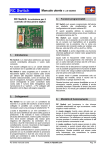
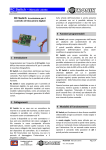
Flashing Light Controller
The first programmable
Flashing Light Controller
for RC applications!
User’s Manual V. 2.0 06/05
2
Overview
Flashing Light Controller is a sophisticated
electronic board that interfaces your RC system
with four flashing and one ON/OFF light channels.
Design your own flashing sequence on your PC
using up to 4 light channels plus an additional
ON/OFF output for green & red navigation lights,
simulate the visual effect and download data to
the FLC Flashing Light Controller!
Each output is capable of driving up to 6 white hibrightness LEDs at low voltage, avoiding the risk
of using dangerous hi-voltage flashers.
Perfect for night flying and for adding more
realism to your RC scale models. Change the
flashing light effect during flight with a touch on
your RC transmitter!
FLC can be connected to a dedicated channel or
can be used in parallel with an existing function of
your RC system. The ON and OFF position can
be user-programmed, so there is no need to
modify your radio set-up.
An additional ON/OFF channel is provided for
solid red and green navigation lights.
3
Connections
FLC comes with a standard connector (available
in Futaba and Universal versions) that can be
plugged into a free channel of your receiver. If you
are planning to use an existing function, a Y
harness adaptor is required.
The controller has a 10 pin output arranged for a
compact 10 pin flat cable connector. In this way it
is very easy to disconnect the controller and to
move if from one model to another one.
A 4 pin connector is provided for programming
and setup operation. The controller has its own
internal voltage regulator, so when connected to
the PC for programming, it can be powered with a
battery (7 to 15 volts) without need for the
complete RC system.
FLC board compared with EU and US cent
1
Characteristics
•
The first user programmable light controller
•
Based on advanced flash microcontroller
•
Small dimensions: 16 x 30 mm
•
Four independent flashing channels (circuits)
•
One ON/OFF channel for r/g navigation lights
•
Up to 6 LEDs drive capability for each channel
•
Six programmable sequences available
•
Up to 32 steps for each sequence
•
RS232 serial link for PC programming
•
PC editing software
•
PC visual flashing effect simulation
•
Sequence store / recall on disk
•
Flashing effect WEB downloadable archive
•
Adjustable RC interface parameters
•
Futaba and JR/Graupner/Universal connector
•
SMD and traditional LEDs available
RC Switch instruction manual
An LED on the controller board is used to identify
the state of the controller and the communication
flow with the PC.
4
Flash sequences
The FLC can store in its non volatile memory six
independent flash sequences (data are retained in
memory even if the power is disconnected).
A sequence is a number of steps (up to 32) in
which each light output channel (circuit) can be
programmed to be ON or OFF. The sequence is
repeated continuously until a RC command is
received; immediately, the next sequence will
start.
For each sequence it is also possible to define the
step time (the minimum ON and OFF period)
starting from 0.02 seconds up to several seconds.
Equally, the on/off state of navigation lights (light
channel 5) can be set.
www.rc-flysoft.com
Page 1/10
Flashing Light Controller
User’s Manual V. 2.0 06/05
5
When programming:
Board connections description
Servo cable:
must be connected to a channel of the RC
receiver; available in Futaba or Universal
(Graupner/JR/Hitec) version.
Servo cable:
disconnected
VBatt:
disconnected
Light connector: disconnected
Serial connector: P1: GND (Power)
P2: +7/15 DC power supply or
6 to 12 cells battery pack.
Serial connector:
P3: RX to PC Serial
connects the PC serial port and power
supply during board data programming. A
wall adaptor, a power supply or a battery
pack can be used in the range 7-15 volts
DC, 100 mA and must be connected to pin
P2 (positive) and P1 (GND).
P4: GND to PC Serial
When in use:
Light connector:
10 pins for 5 light channels (circuits) LED
connection. On the inner column there are
the active low commands for each channel.
The external column is connected to the
LEDs positive supply (VBatt). It is possible
to wire LEDs with a common positive and
then with a separate negative for each
channel, or to use two wires out of the
connector for each LED channel in
sequence: GND and positive for each
channel. The first 4 light channels can be
used as flashing lights, while the last one
(channel 5) can only be programmed ON or
OFF in each sequence and can be used for
navigation lights.
VBatt:
common positive power supply for all LEDs
from the main battery. It can be connected
to one or more light connector pins (if not
used for LEDs) or to a pad located on the
bottom side of the circuit. A small connector
can also be used to make the board easy to
remove.
RC Switch instruction manual
Servo cable:
to receiver channel
VBatt:
to positive end of main battery
pack (see details for allowable
number of cells).
Light connector: to light system (LEDs)
Serial connector: disconnected
www.rc-flysoft.com
Page 2/10
Flashing Light Controller
User’s Manual V. 2.0 06/05
6
9
Mode selection
Great care must been taken to ensure your
safety. If you make the mistake of turning on your
receiver BEFORE switching on your transmitter,
nothing will happen. The lack of two short blinks
on the board LED and on light channel 4 will warn
you that you have made an error.
You should always turn on your transmitter
BEFORE activating your receiver to ensure
that you have control over all functions.
The selection between modes is automatically
done by the interface at the start-up. If command
pulses from the RC receiver are detected, the
controller starts in operation mode; otherwise the
programming mode is entered. Do not power on
the interface if the PC is connected and it is
sending data. This can start the operation mode.
7
Each channel can drive up to 6 high-intensity
LEDs. Each LED must be wired with the cathode
connected to the desired channel output and the
anode to the VBatt via a resistor.
Important notice: never connect the LED
directly to power (VBatt) without the
resistor. This will destroy the LED and
can damage the interface.
If you buy the LEDs as part of the kit, resistors are
already provided and you can select the option for
7 or 8 cells battery pack. If you have different
battery pack, or you have already LEDs installed
on your model, you have to calculate the most
appropriate resistor value.
The formula is very simple:
R = (VBatt – Vled) / iLed
Operation mode
When the board is connected to the RC system,
the operation mode is automatically selected.
Two short blinks on the board LED (and on light
channel 4) indicate that the system is ready to
operate. All the channels are off until the first
command from the receiver is detected. Then the
first sequence starts and it is played until a new
command is received. To change from one light
sequence to another, you must first give the OFF
command and then the ON command. After the
last sequence (6) a dummy ‘blank’ sequence is
automatically inserted, in which all outputs are in
the off condition. The system will restart from the
first sequence at the next command.
Mode detect
Cmd
Seq 2
Seq 1
2 Blinks
LED resistor calculation
Seq 6
Blank
R=
resistor value in ohms
VBatt =
battery voltage (volts)
VLed =
LED forward voltage (volts)
iLed =
LED current consumption in amperes
The LED in the kit must be powered at 30 mA
(0.03A) max and has a forward voltage of 4V. If
you use this LED connected to a 8 cells battery
pack (1.2 x 8 = 9.6V), the resistor value will be:
R =(9.6-4)/0.03 -> 186 adjusted to 180 ohms
If the same LED is connected to a 7 cell pack:
R =(8.4-4)/0.03 -> 146 adjusted to 150 ohms
In chapter 12 there is a table with the adjusted
value for the LEDs from 20 to 35 mA and battery
packs from 6 to 10 cells (7.2V to 12V) for white
LEDs. When connecting more than one LED to
the same light channel, use a separate resistor for
each LED.
VBatt
Cmd
Resn
Cmd
8
Programming mode
A
LED1
When the board is powered without a connection
to the RC receiver, the programming mode is
entered. The board LED is turned on and starts
blinking during data transfer.
When the programming is finished the LED is
turned off and the interface must be re-started.
RC Switch instruction manual
www.rc-flysoft.com
LEDn
K
Channel output x
Page 3/10
Flashing Light Controller
User’s Manual V. 2.0 06/05
10 How to wire LEDs
Second option ‘Common positive (VBatt)’:
There are different options for LED connections;
the GND to each LED is controlled by the FLC,
while the Positive must be wired to the LED. It is
recommended that you connect each LED to
VBatt using a separate resistor for each LED.
-
-
-
First option ‘Separate wires’:
-
This configuration uses a flat cable or separate
plug with two wires for each LED.
LED
+
+
RES
Pin 1
For the light connector pin-out, please refer to
section 13: Board connections diagram.
-
LED
LED
LED
LED
+
+
+
RES
RES
RES
VBatt
RES
Pin 1
-
Schematic diagram of light channels (circuits) 1-4
LED
+
-
LED
+
RES
-
LED
+
RES
RES
In this configuration, LEDs are connected with a
common wire to VBatt and with the other pin to
the Flashing Light Controller board.
Schematic diagram of light channels (circuits) 1-4
This is the preferred configuration when LEDs are
placed in the same area (i.e. on the wing) as it
minimizes the number of wires (4+1 instead of 8).
The wires of the flat cable can be separated in five
pairs. The first from the top is light channel 1 (and +), the second is light channel 2 (- and +),
and all other light channels are in the same order.
The VBatt (positive) must be connected to the red
wire marked ‘VBatt’ and it is transferred on the
board to the ‘+’ pins of the connector.
This configuration is suitable when LEDs are
located in different parts of the model. In this way,
for each LED there is a simple two cable pair.
Don’t forget to connect the right resistor in series
with the LED!
RC Switch instruction manual
In this case it is possible to use a single line
connector for the four light channel connection.
The red wire soldered on the pad close to the
connector (VBatt) is not needed as it normally
used only to transfer VBatt voltage on the pins of
the connector, that are not used in this
configuration. Power from the battery (VBatt) must
be connected directly to the LEDs positive pole.
If you are planning to connect LEDs on both wings
in symmetrical position, you have to connect two
separate wires on each channel pin of the
connector - one for the right wing and the other
one for the left wing.
www.rc-flysoft.com
Page 4/10
Flashing Light Controller
User’s Manual V. 2.0 06/05
As an alternative, you can use the flat cable
crimping the connector in the middle of the cable,
as in the example:
Traditional version:
SMD version:
You have two pairs of wires for each channel, one
for the right and one for the left wing. The L and R
end of each light channel are connected to the
same light channel pin.
11 LEDs in the kit
12 LED resistor selection table
You can use any type of LED with the FLC board.
The right resistor value must be calculated
according to the battery pack size and specific
LED characteristics.
White LED, forward voltage = 4V
Number of cells / voltage
Current
6 / 7.2
7 / 8.4
8 / 9.6
10 / 12
The LEDs offered in the kit are available in two
formats: traditional and SMD.
20 mA
160
220
270
430
Both are hi-brightness white LED and both are
supplied on a small PCB board (11x11 mm.)
including the required resistor.
25 mA
130
180
220
330
30 mA
110
150
180
270
35 mA
91
120
160
220
Note: some resistor values are non-standard and can
be found in the 1% and 2% tolerance series.
13 Board connections diagram
Each board has two large pads for easy wire
connection, very useful in the common VBatt
configuration, as a rigid wire can connect and hold
in place the boards with LEDs.
The traditional one has the LED on one side and
the resistor and connection pads on the other one,
while the SMD version has all on the same layer.
Light
connector
Servo
cable
LED
P1:
P2:
P3:
P4:
GND
+7/15V
Rx
GND
Pin 1
L. Ch. 1
L. Ch. 2
L. Ch. 3
L. Ch. 4
Nav Light
Nav Light
V
B
A
T
T
Serial
connector
VBatt
(bottom side)
RC Switch instruction manual
www.rc-flysoft.com
Page 5/10
Flashing Light Controller
User’s Manual V. 2.0 06/05
14 Programming the controller
port. The communication is one-way only from the
PC to the Flashing Light Controller board, so it is
not possible to check and correct transmission
errors. In case of error, it is necessary to retry the
data transmission.
The controller can be programmed to reproduce
your personal flashing sequences using a PC and
the dedicated software. During this procedure, it is
also possible to setup the polarity and the
command/stick travel of the RC system you want
to use to control the interface.
The interface comes with a pre-programmed set
of flashing sequences and with the input channel
programmed to detect the ON (start of the next
sequence) at more than 60% and the OFF
(command release) at less than 20% of the total
command/stick travel.
If you have a dedicated channel for the Flashing
Light Controller, you can operate the interface at
the default values, adjusting the travel and polarity
on your transmitter.
The LED on the board is switched on when power
is applied to the board and will flash during
transmission to indicate that the data are received
from the PC.
To start-up the Flashing Light Controller board in
programming mode, simply apply power (7-15
volts DC) with the servo cable disconnected. The
LED on indicates that the board is ready to
receive data.
The program panel is divided in different sections
(see picture):
Command Menu (a)
Name of the file in use (b)
15 Software
Sequence selector (c)
The programming software is very easy to use. It
can also be used ‘off line’ with the FLC board
unconnected. You can edit, simulate and save
your sequences or recall them from disk for
adjustment and modification.
When you have completed the six sequences, you
can connect the Flashing Light Controller board
and transfer the data.
The connection uses the serial line and it is
possible to setup COM1 to COM4 as the output
RC Switch instruction manual
Navigation light selection (d) and indicator (e)
Sequence editor (f)
Program button (g)
Time base selector (h)
Simulation panel (i)
Simulation button (j)
Progress bar (k)
Exit button (l)
www.rc-flysoft.com
Page 6/10
Flashing Light Controller
User’s Manual V. 2.0 06/05
15.1 Command menu
Communication sets the serial port to be used to
send data to the FLC board. The selection is from
COM1 to COM4. If one or more of these ports are
not present on your computer, or are not available
at the moment (i.e. used by other applications)
they are grayed and cannot be selected.
The Command menu contains three functions:
File, RC-Set Up and Communication.
File can load and save data patterns on disk. In a
file are saved all the six sequences, each one with
its time base and navigation light state (ON/OFF).
Selecting the save or the recall option, a standard
file dialog box will be opened and it is possible to
select the drive and the location in which the file
can be saved or loaded.
The other parameters (speed, number of bytes,
parity) are fixed and cannot be changed.
The last Exit option will terminate the program as
the Exit button in the bottom right corner.
15.2 File name
RC-Set Up will adjust the interface parameter to
decode the RC channel command.
The Filename (name of the file in use) is shown
immediately after the sequence selector. All the
six sequences are stored in one file.
15.3 Sequence selector
Two separate slides control the OFF and the ON
threshold positions. A bar-graph on the bottom
displays position and amplitude of the commands:
in red the OFF (neutral) position (default set-up
from 0 to 20%), in green the ON (active) area from
60% to 100% and in yellow the hysteresis zone:
the valid command on must be greater than 60%
and the command release is under the 20% limit;
in the middle the command is undefined.
It is possible to reverse the two limits by simply
moving the OFF slide up and the ON slide down.
The Done button will close the window and saves
the selected values.
RC Switch instruction manual
The sequence selector indicates the sequence in
use and allows you to select a different one for
editing or for simulation. All the six sequences are
held in memory and it is possible to edit part of a
sequence, select another one, edit a part of the
second sequence and go back to the first one or
move to a different one. It is not possible to modify
the default name of sequences, marked as
Sequence 1 to Sequence 6.
Moving from one sequence to another one will
also automatically up-date the Navigation Lights
indicator and the time-base selection to their new
values.
15.4 Navigation light selector and indicator
This control toggles ON and OFF the state of
navigation lights (channel 5) output for each
sequence. The indicator turns GREEN when ON
in the current sequence and in RED when OFF.
www.rc-flysoft.com
Page 7/10
Flashing Light Controller
User’s Manual V. 2.0 06/05
15.5 Sequence editor
To create your personal sequences you can start
from an existing pattern or from scratch. When
you start from an empty sequence, the end of
sequence marker is automatically placed at the
end of the sequence. Move the cursor to the
position you want to edit and click to select the
current position or double-click to toggle between
ON and OFF. By selecting a cell, you identify the
current step and channel, and you can apply the
following editing commands:
This is the main working area of the program in
which it is possible to create the flashing
sequences. It is divided into four rows, one for
each output channel (circuit), marked as Light
Chan. 1 to 4.
The four rows are divided in 32 columns, marked
as step 1 to step 32 (S1–S32). A bar under the
working area allows you to move horizontally to
reach the last column. Each column (S1, S2, …)
represents a fixed time interval. For each interval,
it is possible to select the state of each light
channel (ON or OFF).
ESC:
Clear all data of all channels of the
current sequence (no need to select a
cell).
Playing all the columns in sequence will create
the flash effect. The time interval is the same for
all the steps in the sequence and can be modified
using the time-base selector.
C:
Clear all data in the current channel
starting from the current position to end.
D:
Delete the selected step in the current
channel.
To create a simple flash sequence (see example)
on channel 1 with half second ON and half second
OFF, S1 must be programmed ON, S2 must be
programmed OFF and the sequence can be
terminated. The S1 and S2 steps are executed
continuously, creating a 50% ON and 50% OFF
flash effect.
CTRL D: Delete the selected step in all channels.
I:
Insert a new step in the current position,
in the current channel.
CTRL I: Insert a new step in the current position
in all channels.
E:
Place the end-of-sequence marker,
which is displayed as a red column.
H:
Recall the help frame with the available
command description.
15.6 Time–base selector
The time-base indicator must be adjusted to the
required time interval, in the example 0.5
seconds.
The green box indicates channel ON, clear box
indicates channel OFF and the red column will
terminate the sequence.
Changing the time base will slow down or
accelerate the flash frequency, but the duty cycle
of 50% remains the same.
To create a different effect, with two short pulses,
one long, two short and a pause, the pattern is:
The three steps S5, S6 and S7 will create the long
pulse ON, while S12, S13 and S14 are the long
pause before repetition.
RC Switch instruction manual
The time-base selector allows you to set-up the
time interval of each step in the current sequence.
The allowable values are from 20 msec up to 5
sec, advancing in a 20 msec step. On the
Flashing Light Controller board, this time can
change from 20 to 25 msec, as it is synchronized
with the RC-receiver channel scan rate.
15.7 Simulation panel & button
The simulation panel reproduces the running
sequence by switching ON and OFF four white
dots, one for each light channel (circuit). You can
see the real visual effect of the sequence and
while the simulation is running, you can modify the
time-base setup, or you can edit/modify the
sequence having an immediate visual feedback of
the resulting effect.
The simulation is toggled ON and OFF with the
simulation button and it is automatically turned
OFF during data downloading to the Flashing
Light Controller board.
www.rc-flysoft.com
Page 8/10
Flashing Light Controller
User’s Manual V. 2.0 06/05
15.8 Program button
The state LED on the flashing controller board will
flash to indicate the correct data flow.
This button starts data download to the Flashing
Light Controller board. Be sure that the PC is
connected to the FLC board and that the board is
powered with the state LED on.
Before using this function, the right COM port
must be selected.
During data transfer, the simulation is switched
off, and the sequence selector will indicate which
sequence is currently being transferred.
15.9 Progress bar
It is normally not-visible, and will appear during
data save, load and send, to indicate the progress
of the operation.
16 Default sequences
Sequence n. 1 Nav. Light ON
Timebase = 0.060
Ch. 1
Ch. 2
Ch. 3
Ch. 4
Sequence n. 2 Nav. Light OFF Timebase = 0.060
Ch. 1
Ch. 2
Ch. 3
Ch. 4
Sequence n. 3 Nav. Light ON
Timebase = 0.100
Ch. 1
Ch. 2
Ch. 3
Ch. 4
Sequence n. 4 Nav. Light OFF
Timebase = 0.080
Ch. 1
Ch. 2
Ch. 3
Ch. 4
Sequence n. 5 Nav. Light ON
Timebase = 0.060
Ch. 1
Ch. 2
Ch. 3
Ch. 4
Sequence n. 6 Nav. Light OFF Timebase = 0.160
Ch. 1
Ch. 2
Ch. 3
Ch. 4
RC Switch instruction manual
www.rc-flysoft.com
Page 9/10
Flashing Light Controller
User’s Manual V. 2.0 06/05
17 Additional notes
Throughout this document, the term ‘light channel’ is used with the meaning usually attributed to that of an
electrical circuit. The controller board is plugged into only one “channel” of your receiver. This channel can
be either a toggle switch, such as the gear UP/DOWN, or an unused stick channel such as the rudder.
The LEDs need to be provided with a positive power source. If you are using only four LEDs, a workable
solution can be achieved using only the 4.8 volts from the receiver battery pack. All you have to do is attach
the Vbatt red wire of the controller board to the positive wire of a spare female servo plug. Insert that plug
into a spare channel on your receiver and you have provided the positive power source. The controller
board will pick up the ground for the circuit from the ground on the three wire servo extension that is attached
to the controller board right beside the board LED. Please note that, in this case, the required resistor value
is ly 33 ohms, due to very low voltage of the battery (4.8 volts) compared with the forward voltage of the
white LED (4 volts).
If you want really bright lights, and you are using 8 LEDs, then you should use an external power pack, such
as the one connected to your ESC. Connect the red Vbatt wire from the controller board to the positive side
of your ESC power source. If the ESC is supplying the receiver via the BEC circuit the GND return is already
ensured by the receiver connection.
If you are using an external battery not connected to your RC system the negative pole of the battery (GND)
must be connected to the FLC. You can pick up controller board ground from either P1 or P4 of the serial
interface connector.
When connecting the serial interface connector, please make sure that it is connected with red dot facing up.
The external battery source is connected to the two pins (1 and 2) closest to the controller board LED.
RC Switch instruction manual
www.rc-flysoft.com
Page 10/10