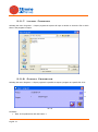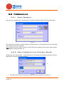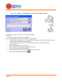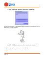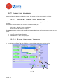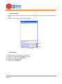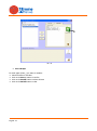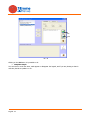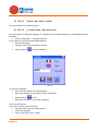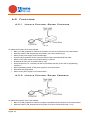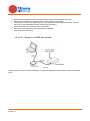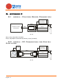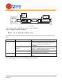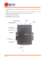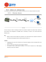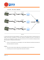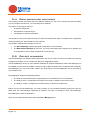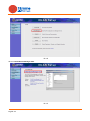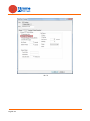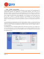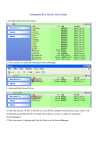
1
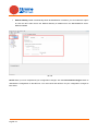
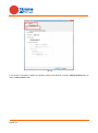
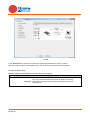
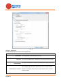
System Evolution 4.0 Full/Light User Manual English 1 Sommario 1. SYSTEM REQUIREMENTS ........................................................................................................ 4 2. INSTALLATION ........................................................................................................................ 4 3. CONNECTIONS ........................................................................................................................ 5 4. START ....................................................................................................................................... 6 5. MENU........................................................................................................................................ 7 5.1 5.2 QUICK SELECTION BUTTONS ................................................................................................. 7 REMOTE CONTROL SELECTION BUTTON. ................................................................................... 8 5.3 5.4 5.5 ADDRESS BOOK ................................................................................................................ 11 LOGGER PROCESSING ........................................................................................................ 13 PROGRAMS....................................................................................................................... 15 5.6 PROGRAMMING ................................................................................................................. 24 5.7 MONITOR LOGGER............................................................................................................. 29 5.8 5.9 LAB MODE [FULL] ........................................................................................................... 37 TOOLS ............................................................................................................................. 41 5.10 CONFIGURATION ............................................................................................................... 43 5.2.1 5.2.2 5.2.3 Serial Port ............................................................................................................... 8 GSM Modem ............................................................................................................ 9 TCP/IP – NETLink ................................................................................................. 10 5.5.1 5.5.2 5.5.3 5.5.4 5.5.5 5.5.6 5.5.7 5.5.8 5.5.9 Programs Management [Full] ............................................................................... 15 Program List [Light] .............................................................................................. 16 Edit Program [Full] ............................................................................................... 16 Parameter List [Light]........................................................................................... 18 Description Database Modify [Full] ...................................................................... 18 Copy Program [Full] .............................................................................................. 21 Import Program .................................................................................................... 22 Export Programs ................................................................................................... 22 Print Program........................................................................................................ 23 5.6.1 5.6.2 5.6.3 5.6.4 5.6.5 Read Program ....................................................................................................... 24 Write Program into Control Board ........................................................................ 24 Write Program into Programmer .......................................................................... 26 Control board firmware upgrade .......................................................................... 27 USB_Programmer’s firmware Update ................................................................... 27 5.7.1 5.7.2 Update / Insert New Monitor ............................................................................... 29 Start Monitor / Logger .......................................................................................... 29 5.9.1 5.9.2 5.9.3 5.9.4 Import Database ................................................................................................... 41 Export Database.................................................................................................... 41 Creating custom Database .................................................................................... 41 Backup Database .................................................................................................. 42 5.10.1 5.10.2 5.10.3 5.10.4 Change Password .................................................................................................. 43 Printer Settings ..................................................................................................... 44 Language Selection ............................................................................................... 44 Product Code ......................................................................................................... 45 6. APPENDIX A ........................................................................................................................... 47 6.1 USB_PROGRAMMER .......................................................................................................... 47 6.1.1 6.1.2 English 2 Buttons .................................................................................................................. 47 Led ........................................................................................................................ 47 6.2 FUNCTIONS ...................................................................................................................... 48 6.2.1 6.2.2 6.2.3 7. Update Control Board Firmware ........................................................................... 48 Update Control Board Program ............................................................................. 48 Serial-USB Adapter ............................................................................................... 49 APPENDIX B ........................................................................................................................... 50 7.1 8. INSTALLING DRIVERS USB PROGRAMMER ............................................................................. 50 APPENDIX C ........................................................................................................................... 51 8.1 8.2 8.3 9. MODEM – CONTROL BOARD CONNECTION .............................................................................. 51 MODEM – PC CONNECTION FOR SYSTEM EVOLUTION ............................................................... 51 LED MODEM STATUS. ......................................................................................................... 52 APPENDIX D NET LINK ......................................................................................................... 53 9.1 9.2 INTRODUCTION ................................................................................................................. 53 OVERVIEW OF THE PRODUCT ................................................................................................ 53 9.3 MODE OF OPERATION ......................................................................................................... 55 9.4 9.5 CONFIGURATION METHODS ................................................................................................. 57 DEVICE MANAGER .............................................................................................................. 57 9.6 WEB MANAGER ................................................................................................................. 71 9.2.1 9.2.2 Hardware Components ......................................................................................... 53 Key features .......................................................................................................... 53 9.3.1 9.3.2 Server Mode .......................................................................................................... 55 Client Mode ........................................................................................................... 56 9.5.1 9.5.2 Configures an IP address ...................................................................................... 59 Configuration of serial port ................................................................................... 63 English 3 1. System Requirements Systems Evolution 4.0 requires one of the following operative systems: Windows XP Professional / Home edition Windows Vista Windows 7 Windows 8 The PC needs the following minimum requirements: Operating System Windows XP Professional / Home Edition Windows Vista, Windows 7 and Windows 8 Minimum Requirements Intel Pentium or compatible 300 MHz or superior 125 MB RAM 60 MB memory CD-ROM or DVD-ROM unity Processore 800 MHz 512 MB di RAM 20 GB di spazio disponibile su disco rigido Unità CD-ROM Note: To install and use Windows XP, needs administrative account. For installation and importing files monitor on Windows Vista, Windows 7, Windows 8 you need an account with administrative privileges, for use it is sufficient a default user account. 2. Installation To install System Evolution 4.0: close all programs insert the CD in the CD-ROM unit, click on setup.exe and follow the wizard procedure. English 4 3. Connections Pic. 1 Connect the PC to the serial port RS232 of the control board through the USB Programmer. Supply the control board at 230 V / 50 Hz (see Pic.1). To connect System Evolution by remote please refer to Appendix C and D. English 5 4. Start To start the software : Select Start Programs TiEmme elettronica System Evolution 4.0. First time System Evolution 4.0 starts up it requests to choice the language. You can choose Italian, English or another one (but you have to translate each word! See sec. 5.10.3). Pic. 2 To start the program it is necessary to insert user name and password. The default user name and password are: Username: Password: user user Pic. 3 Push the button English 6 to confirm or to exit. 5. Menu Pic. 4 Pic. 5 5.1 Quick Selection Buttons English 7 Product Identification Open the window to recognise the connected product Programs Managements Open the window to modify and create new programs for the selected product Modify Programs Open the window to modify the selected program’s data Copy Programs Open the window to copy a recipe Read Program Starts the parameters’ reading procedure from the Control Board’s memory Write Program’s Parameters Open the window to write the selected program’s parameters in the Control Board’s memory Print Programs Open the window to print the selected program Logger processing Open the window for processing saved logger Address book Opens the window with the data of customers Connection Mode Opens the window to choose the mode of connection to the control board Lab Mode Opens the lab environment for the development of new programs 5.2 Remote control selection button. Clicking on the icon to open the window to choose the connection mode for the software to perform the tasks of management and control. It’s also possible to use the following path Configuration Connection mode Pic. 6 5.2.1 Serial Port This section shows how to connect via the serial port. Control board. To download the firmware and programs on the control board, with the following configuration USB programmer connected to the PC via USB and control system connected to the USB programmer; USB Programmer. To Load the programs on USB Programmer connected to the PC; COM Port Selection: To find out in which COM port you have connected the USB Programmer Select the port number from the drop-down menu and then click on the Connect button; Automatic selection and connection to the COM port with the Search button English 8 5.2.2 GSM Modem Pic. 7 In this section is possible to connect to the control board via the GSM modem. COM Port Selection: Select the COM port drop-down menu to select the COM port where is connected the modem; Check Modem: to test the Modem connection with the selected COM port; Address Book to open the Address Book and to select the number for the connection; Phone number: to enter directly the phone number , for example in the case that it is not in the address book. System Evolution 4.0 allows the use of a modem (supplied) for connection with a remote control board. The customer care support center will provide local modem with a SIM card that supports a GSM data connection. The user of the stove will connect the modem (supplied) and provide it with SIM card that supports a GSM data connection and with PIN request disabled. Although the software and the control board are equipped with an idle connection timeout of 5 minutes (after which the modems are disconnected), it reminds the end user of System Evolution to Switch off the modem whenever it is unused. TiEmme Elettronica assumes no liability in case the modem will remain active indefinitely. At the end of the use of remote control, press Disconnect to end communication with remote control board. If System Evolution should indicate errors during the disconnection, we recommend turning off the modem. Please note that if the active connection is not used for longer than 5 minutes System Evolution and / or the control board will terminate the connection for inactivity. Once it’s connected System Evolution will work like the local connection. English 9 5.2.3 TCP/IP – NETLink Pic. 8 This section describes the settings required to connect remotely to the control boards via intranet/internet with the product NETLink. Server: when the device NETLink is set as the client and the software System Evolution as a server o Remote Box ID: is the ID of the NETLink device to connect. This field is automatically populated if the address book is used, otherwise is possible enter manually. Client: if the NETLink device is set as a server and software System Evolution as a client; o Remote IP/FQDN: for entering the IP address of the remote NETLink device functioning as a server; Address book: to choose the device NETLink to connect; Box Remote port: specifies the port used for the connection to the NETLink device; All connections incoming or outgoing pass through the port specified in the Remote Box port, which must be the same on device NETLink. English 10 5.3 Address Book System Evolution 4.0 includes a phone book to store contacts for customers using the remote. To open the Address Book and insert, modify or delete contacts, press Contacts in the control bar of System Evolution. To open the address book evolution. and insert new contacts click the Address Book icon in the taskbar system Pic. 9 To add a new contact, press 'Add new contact' button. This will open the form in which will fill in all fields (Name and reference are required). Once created the new contact, add one or more devices to connect by pressing the 'Add Number' button. In the case of IP addresses, use the following nomenclature for the complete identification IPAddress @ portnumber. To edit or to delete the selected contact using ‘Modify contact' or 'Delete contact' buttons. The book is also equipped with a search utility for finding contacts, reference etc.. Selecting entries in the frame 'Search' you can filter your search according to the field. The keys AZ near to items 'Name' and 'Reference' create a sort ascending or descending alphabetical list of contacts according to the name or reference. To exit the Address Book press Cancel / Exit button. English 11 Pic. 10 English 12 5.4 Logger Processing The function allows you to process files even when the logger software is not connected to the control board. Clicking on the icon opens the window for the selection of the logger file saved on the PC. Selecting the files to be processed (Filename SYEVOXXXXXXXX.mdb) opens the window for the selection of the log file. Pic. 11 Selecting the log file to open the editing window. This windows is accessible even from the monitor/logger section English 13 Pic. 12 English 14 5.5 Programs This menu allows to manage, modify, copy, import, export and print the programs. 5.5.1 Programs Management [Full] Selecting the menu Programs Program management appears the window Pic. 13 It is possible to choose a specific program of a product (for example “Default Program” of SY250 Standard cod.177 product). It is necessary to write the code, the description and the author. Pushing the Modify button it is possible to modify the data inserted before. To save data push the Save button. Pushing the New button it is possible to create a new program. The new program is generated after saving data (the parameters’ default value is set by the manufacturer; to change them it is necessary to open the Modify programs menu). Pushing the Delete button it is possible to delete a program. Pushing the Exit button it is possible to exit Pushing the Save button it is possible to save English 15 5.5.2 Program List [Light] Selecting the menu Programs Program List, you can view the products and programs in the database. Pic. 14 For each program displays all available information may be given in the fields Code, Description, Author, Notes, Effective Date, Date of obsolescence. 5.5.3 Edit Program [Full] Selecting the menu Programs Edit program it is possible to modify the parameters’ values for each programs. English 16 Pic. 15 Procedure: Enter in the products list pushing the button Click to Select a product and then double click to choose. It will appear the window Enter in the programs list with the button Click to Select a program and then double click to choose; Select the parameter to modify and change its value in the 'Set' field. This value has to be between the Minimum and Maximum value. Otherwise the value is automatically set to the Minimum or Maximum value. Click the button to enter in modify Click the button to save and record the changes or on the button English 17 to cancel 5.5.4 Parameter List [Light] Selecting the menu Programs Detail parameters you can display the value of the parameters in each program. Pic. 16 Procedure: Enter in the products list pushing the button Click to Select a product and then double click to choose. It will appear the window Enter in the programs list with the button Click to Select a program and then double click to choose; 5.5.5 Description Database Modify [Full] System Evolution 4.0 allows to modify the descriptions of System2000 database. Procedure: Click on button . The window will change colour to indicate a modifiable state. English 18 Pic. 17 Select the description to modify: it will appear; Insert the description and save (click on button ‘OK’) To cancel the new description and restore the old one click on button English 19 Pic. 18 English 20 5.5.6 Copy Program [Full] Selecting the menu Programs Copy program it is possible to copy the data from a program to another one or copy with another name. Pic. 19 Procedure: Enter in the products list with the button Click to Select a product and then double click to choose Enter in the programs list with the button Click to Select a program and then double click to choose Copying a program in another Enter in the destination programs list with the button Click to Select a destination program and then double click to choose Click on the button to start the procedure Copy of the program with a new name Click on the button name. without selecting the destination program to access the dialog for digit a new Pic. 20 Click on the OK button to start the procedure. English 21 5.5.7 Import Program Selecting the menu Programs Import program the system will open a window to chose the file in which there is the program to import. Pic. 21 5.5.8 Export Programs Selecting the menu Programs Export program it is possible to export a program in a specific file of PC. Pic. 22 Procedure: Enter in the products list with the button English 22 Click to Select a product and then double click to choose Enter in the programs list with the button Click to Select a program to export and then double click to choose Push the button to start the procedure 5.5.9 Print Program Selecting the menu Programs Print program it is possible to print a created program. Pic. 23 Procedure: Enter in the products list with the button Click to Select a product and then double click to choose Enter in the programs list with the button Click to Select a program to print and then double click to choose Push the button Use the buttons Push the button to print Push the button to set the printer Push the button English 23 to start the procedure to select the page to visualised to export the selected program in a available size 5.6 Programming 5.6.1 Read Program Select the menu Programming Read program to read the parameters’ values from the Control Board. Pic. 24 The read values are saved in a specific program (Program read from Control Board) and they can be modify, copy and print as the other programs. Note: During the function ‘Program read from Control Board’ don’t modify the data of the program created automatically by System Evolution 4.0. 5.6.2 Write Program into Control Board Selecting the menu Programming Write program into Control Board it is possible to program the Control Board with the values of the desired program. Pic. 25 The software automatically recognises the Control Board connected to the serial port English 24 Push the button to select the program to write in the Control Board Click to Select a program and then double click to choose Start the procedure pushing the button English 25 5.6.3 Write Program into Programmer CN2 Pic. 26 It is possible to do this function only having USB_Programmer. Procedure: Connect USB_Programmer to a PC USB port (if the OS requires the drivers for the new device, see Appendix B) select the menu Programming Write program into Programmer to update the parameters’ value of USB_Programmer with the chosen program Select on USB_Programmer where store the program (Sel1, Sel2, Sel3): see Appendix USB_Programmer Enter in the products list with the button Click to Select a product and then double click to choose Enter in the programs list with the button Click to Select a program to write and then double click to choose Start the procedure pushing the button English 26 5.6.4 Control board firmware upgrade Pic. 27 Select the menu Programming Device Software Manager to download the file with extension .tfw in the Control Board or in the USB_Programmer. CN2 Pic. 28 5.6.5 USB_Programmer’s firmware Update Procedure: Connect USB_Programmer to a PC USB port using the CN2 cable (if the OS requires the drivers for the new device, see Appendix B) Be sure that the used COM port is right (see Appendix B) English 27 Select Programming Device Software Manager: it will appear the window of Errore. L'origine riferimento non è stata trovata. Click on the button "Download firmware in the Programmer" and follow the wizard procedure When required select the file to load in the USB_Programmer (it has extension tfw) At the end of the procedure disconnect USB_Programmer from PC Updating Control Board’s Firmware Pic. 29 To update the board’s firmware from the PC follow this procedure: Connect USB_Programmer to a PC USB port (if the OS requires the drivers for the new device, see Appendix B) Be sure that the used COM port is right (see Appendix B) Connect USB_Programmer to the control board’s RS232 port Click on the "Download firmware in the Control Board" button and follow the wizard procedure When required select the file to load in the Control Board (it has extension tfw) At the end of the procedure: Switch off the power supply Disconnect USB_Programmer from PC and board Switch on the power supply English 28 5.7 Monitor Logger System Evolution 4.0 allows to visualize the inputs, the outputs and the state system in real time. 5.7.1 Update / Insert New Monitor Before start monitor connect the serial cable to the Control Board and supply the Control Board. Procedure: This function allows to install a new monitor or update an existing one. Procedure: Click Monitor Update / Insert new Monitor Find the file with dll extension to import The Logger allows to monitor, to do a graphic and to save data, inputs and outputs used by system to vary of time. To start the Logger / Monitor From the menu of System Evolution Select Monitor -> Start Monitor/Logger 5.7.2 Start Monitor / Logger To monitor the way of system simply click on the button P2 By clicking on the button P1 it is possible to process the data acquired in previous sessions P5 P3 Pic. 30 English 29 P4 P1 P2 Pic. 31 To start a new data acquisition click on P2 button and then click on P3 button. When a new data acquisition starts you have to: Enter the name of the new session (the systems assigns the default name as the current date and time) Select the items to be acquired Set the sampling time (in seconds) Now clicking on the button P1 you can do the graphs and save the data you are acquiring. To end a data acquisition click on the button P2 or P4. To exit click on the P5 button. English 30 Data Processing Choose the work session of interest and click the button P6: now you can do a graph and save data in a .xls file. To delete a stored session, select it and press P7. P6 P7 Pic. 32 To To Export Data Select the items to be exported in the Excel file. Confirm your selection with the Set>>> button select all items click on the Set All button deselect click on Del All button To export click on P8 button. English 31 P8 Pic. 33 For Plot a Graph each graph (Chart_) you want to visualize: Select the items to visualize click on the Set>> button to confirm click on the Set All button to select all items click on the Del All button to clear English 32 P9 P10 Pic. 34 Clicking on the P9 button it is possible to do: Complete Graph You can zoom or scroll the chart, make appear or disappear the legend, and if you are plotting a chart in real time, decide to update it or no. English 33 Pic. 35 English 34 Clicking on the P10 button it is possible to do: Frames Graph You can scroll the chart page by page, make appear or disappear the legend, and if you are plotting a chart in real time, decide to update it or no. Pic. 36 Insert Notes Click on the button P11 to insert notes and comments about the chosen work session, insert the text and press the button OK. For each Logger you can enter more notes; to erase a double-click on the note to be deleted. English 35 P11 Pic. 37 English 36 5.8 LAB MODE [full] The Lab mode provides an environment for the development of programs before being saved in the product database. Clicking on the icon opens the window to start the development of new programs. First of all the software ask if the user want to recover the last work session to the state it was left. If the user will not choose this option, the import procedure will start. Pic. 38 Pic. 39 Importing Data into the development environment by reading the program directly from the control board connected to the PC Importing Data into the development environment from a previously saved program in the product database Clicking on the icon English 37 opens the window for the reading of the date from the control board Pic. 40 Clicking on the icon opens the windows for importing data from a program already in the database of the product. Select the product source, and then the program to proceed with the import. Pic. 41 At the end of import of access to the development environment laboratory. English 38 Check box To select a single parameter Pic. 42 In this section the user is able to use following functionality: Selecting and programming single / multiple parameters into the control board; Changing the set parameters; English 39 Saving in the product database a copies of the program being processed; Opening monitor/logger windows. In case of multiple parameter programming, at the end of this operation all parameters will be automatically deselected For the procedures of editing and updating of the programs is possible to refer at the others paragraph in this manual Clicking on the icon you can save in the product database a copy of the program currently being executed. This opens the following window. Clicking on the icon you can save in the product database a copy of the program currently being executed. Than opens the following window. Pic. 43 To save a copy of the program can proceed in two different ways: Enter a name in the blank field under the heading "Save As". Select icon is replaced with the OK icon that you must click to confirm; Pic. 44 Click on the Select button to choose from a existing program list to overwrite; English 40 5.9 Tools 5.9.1 Import Database Import System Database Click on the Import system database menu to open the dialog box where is possible to select the file System2000.mdb. to import. Import Language Database Click on the Import language database menu to open the dialog box where is possible to select the file Text.mdb to import. 5.9.2 Export Database Export System database Click on the Export system database menu to open the dialog box where is possible to select where the file System2000.mdb will be saved. Export Language Database Click on the Export language database menu to open the dialog box where is possible to select where the file Text.mdb will be saved. 5.9.3 Creating custom Database Click on the Creating custom database menu to open the dialog box where is possible to select products or programs to export. English 41 Pic. 45 Clicking on the Save As button selected elements. 5.9.4 you can save a custom copy of System2000 database with the Backup Database The software automatically performs a backup of elettronica\SystemEvolution\Backup folder in two ways: the system database in the x:\TiEmme Daily Backup. At first start the system creates a backup copy named System2000_YYYYMMAA_bak.mdb; Import Database. For every import operation the software creates a backup copy named System2000_YYYYMMAA_HHMM.mdb. English 42 5.10Configuration 5.10.1 Change Password This menu allows to change the password of System Evolution 4.0. Pic. 46 To change the password: Insert the current password in the field Old Password Insert the new password in the field New Password Insert the new password in the field Confirm Password Save data pushing English 43 5.10.2 Printer Settings This menu allows to set system’s printer. 5.10.3 Language Selection This menu allows to change the language. It is possible to select Italian, English or a customizable language. Procedure: Select Configuration Language Selection If you want to use the third customizable language: Select ‘My language’ Insert the name of the language in the box Push the button to do the translation Pic. 47 To insert the translation: Click on the line where insert the translation Write the translation in the white box at the right bottom Push the button to save Repeat the procedure for the other translation There are several tools: find–cerca: to search a word in the list Write the word in the white upper left box •Select the language •Click on the button "find - search" English 44 all–tutti: to see the full list of the used words •Click on the button "all-tutti" Not Translated Words Visualization: Push the button Pic. 48 5.10.4 Product Code Select the menu Configuration Product Code to access the display window of the product identification data. English 45 Pic. 49 English 46 6. Appendix A 6.1 USB_Programmer USB_Programmer is a device which allows to: Save three programs to modify the Control Board functioning Update the control board with a Program set Save a firmware Update the control board with the saved firmware CN2 L1 POWER COM L2 DONE L4 READY L5 S READY P P1 SEL P2 L6 SEL1 AM GR RO START L3 ERROR FW CN1 SEL2 SEL3 L7 L9 Pic. 50 6.1.1 Buttons Button Code Function P1 START Start programming P2 SEL Select parameters’ program 6.1.2 Led Led Code L1 POWER L2 COM / DONE L3 ERROR L4 FW / READY L5 READY L6 SEL1 Led ON: program nr.1 selected L7 SEL2 Led ON: program nr.2 selected L8 SEL3 Led ON: program nr.3 selected English 47 Function Led ON: Programmer supplied Led ON: programming completed Led blinking: programming in progress Led ON: error Led ON: Programmer ready to update the board’s firmware Led ON: Programmer ready to update the board’s parameters 6.2 Functions 6.2.1 Update Control Board Firmware Pic. 51 To update the firmware of the Control Board: Make sure USB_Programmer contains the firmware you want to download on the Control Board Otherwise load on USB_Programmer the firmware you want to download (0) Switch off the power supply to the Control Board Connect USB_Programmer to the connector RS232 of the Control Board via CN1 cable Switch on the power supply to the Control Board (L1 LED On) Check that the LED L4 is on and the LED L3 is off Press the button P1 for 3 seconds: the LED L2 first blinks and then, at the end of programming, remains on After programming switch off the power supply to the Control Board Disconnect USB_Programmer Switch on the power supply to the Control Board 6.2.2 Update Control Board Program Pic. 52 To update the program of the Control Board: Make sure USB_Programmer contains a program compatible with the firmware of the Control Board Otherwise load on USB_Programmer the program you want to download (See par. 5.6.3) English 48 Connect USB_Programmer to the connector RS232 of the Control Board via CN1 cable Select with the P2 button the program (SEL1, SEL2 or SEL3) to download Verify that the L5 LED is on and the LED L3 is Off (otherwise select a different program, because that choice is not compatible with the Control Board’s firmware) Press the button P1 for 3 seconds: the L2 LED blinks When the L2 LED becomes On the programming is finished Disconnect USB_Programmer 6.2.3 Serial-USB Adapter Pic. 53 USB_Programmer is also a Serial-USB adapter to update the parameters and firmware of the Control Board by PC. English 49 7. Appendix B 7.1 Installing Drivers USB Programmer The installation of the drive needed to interface with the USB Programmer is performed during the installation of the Software System Evolution. In the event that the automatic installation is will not close correctly it is possible to do this manually, by running the setup file USBdriverssetup.exe present in the installation cd into the directory X:\Drivers folder (where X identifies the driver where is present the CD-Rom). During the installation process will be automatically assigned (by the operative system) the first number COM port available. In case of communications problems with USB programmer device is necessary to check (in the Device panel for Vista, Win 7, Win 8, and in the device manager for Win XP) the number of the port assigned by the system. If the Com port number is out of the range 1-16, is necessary to manually reassign a port number in the range indicated. All drivers are digitally signed by TiEmme elettronica to guarantee the origin, English 50 8. Appendix C PW_1 Alimentatore Power Supply CAB_2 Modem CN3 Control Board RS232 Scheda di Controllo CN4 CON_2 230 Vac 8.1 modem – Control Board Connection Pic. 54 CAB_2: plug to plug cable. (furnished) CON_2: plug adaptor to DB9 male high density (15 pin) (furnished) PW_1 USB Programmer USB Alimentatore Power Supply CN4 CAB_1 CN3 RS232 Pic. 55 English 51 Modem 230 Vac 8.2 modem – PC Connection for System Evolution CAB_1 230 Vac CN4 CON_1 CN2 POWER DONE ERROR READY P USB COM FW READY SEL3 SEL2 SEL1 A MS GR RO PW_1 Alimentatore Power Supply CN3 CN1 Modem START SEL USB_Programmer Pic. 56 CAB_1: DB9 pin female to DB9 high density male (15 pin).(furnished) CON_1: plug adapter to DB9 pin (furnished) 8.3 Led Modem Status. We include a table summarizing the status of the modem which refers to the yellow LED on the side of the device: GSM LED ON LED activity LED on fixed LED flashing (once every 2 seconds) LED flashing (once a second) OFF LED off Modem Status The modem is powered, it is ready to function but not yet recognised by the network; the PIN code has not yet entered or the antenna is not connected. The modem is powered, the PIN code is active, the modem is recognised by the network and is ready to make or receive a call (Idle mode). The modem is powered and currently in communication (Voice, Data or Fax) The modem si not powered or is in the RESET phase Note: Please disable PIN request on SIM card before insert in modem. English 52 9. Appendix D NET Link 9.1 Introduction Net Link is a converter serial / ethernet able to connect to the LAN the TiEmme Elettronica control boards equipped with RS232 interface. Using NETLink and System Evolution 4.0 is possible to perform all management operations by remote, using as the connection mode the local LAN or internet. 9.2 Overview of the product 9.2.1 Hardware Components Components included The following components are included with the product: NETLink unit External power supply A CD-ROM containing documentation, firmware, configuration software, etc. Plug RJ11 DB25 Serial Port adapter; Connection cable with plug RJ11 Components not included Ethernet cable CAT5 10/100/1000BASE-T for connection to the Network; 9.2.2 Key features This section describes the hardware components found on your NETLink unit Serial Port: the twill be used to connect to control board.; Activity: This LED flashes to indicate LAN activity. Link10/100: This LED indicates the Ethernet connection speed: Green:10 Mbits Yellow: 100 Mbits Off: no LAN connection Power/Ready: This LED can cycle through several colors (yellow, green, red) during a boot process, but should complete with a solid green light. If the LED is green after power up but continues to cycle on and off (flashes green), this indicates that the console switch is in the on position. External Power Supply: This is an external AC power supply. English 53 Console/Serial Switch: This switch determines whether serial port functions. The switched must be set to OFF; Reset: The inset RESET button will reboot the NETLink if pushed in and released quickly. It will reset the NetLink to factory defaults if pushed in and held for more than three seconds. Tx: Flashes with transmit serial activity Rx: Flashes with receive serial activity 10/100 Ethernet: The Ethernet connector. Pic. 57 English 54 9.3 Mode of operation This chapter provides information about the different methods you can to configure the NETLink product 9.3.1 Server Mode Control Board NetLink Router / Switch Client PC with SE 4.0 Serial Cable Ethernet Cable Internet / Intranet Client PC with SE 4.0 Pic. 58 In Server mode, the device is listening and waits for connection requests from remote clients outside the local network. This configuration is desirable when is necessary to connect to the control board from different areas. Pro Ability to reach the control board from anywhere in the world and from any computer connected to the Internet and equipped with the Software System Evolution 4.0. Counter In presence of a router with a firewall you will need port mapping to direct incoming traffic to the remote Net link. Need to configure the device Net Link with static IP address. Is necessary to have a public static IP address, or in the case of dynamic IP, an DNS mapping services by router on the network. English 55 9.3.2 Client Mode Control Board NetLink Router / Switch Ethernet Cable Serial Cable Internet / Intranet Control Board NetLink Router / Switch Ethernet Cable Serial Cable Internet / Intranet Server PC with SE 4.0 Control Board NetLink Serial Cable Router / Switch Ethernet Cable Internet / Intranet Pic. 59 In client mode the Net Link device attempts to connect to a remote server listens for connections from the outside. Each device is identified by a name (user defined at configuration time) that is sent during the connection. This configuration is helpful in the case where there is a PC are carried out centrally from which all the operations of management and assistance. Pro There is no need to perform any port mapping in your local network that is attached to the product as it is NetLink outbound connections; Counter You cannot connect to devices NetLink from locations different from a central server; The listening server must be configured with static public IP address; English 56 9.4 Configuration methods This chapter provides information about the different methods you can use to configure the NetLink. Before you can configure the NETLink, you must assign an IP address. The steps in chronological order are: IP address assignment; Configurations of the serial port; Configuration of network parameters; The operation of the product requires access to advanced settings that make it unusable some configuration mode proposed by the documentation on the CD-Rom. The possible methods that is possible to use are: The Device Manager software (for initial configuration of new products); The Web Interface Manager (in this case, you must have already been assigned an IP address and is not possible to use for initial configuration of new devices); 9.5 Device manager The DeviceManager is a Windows-based application that can be used to connect to the NETLink to actively manage and configure it or can create new NETLink configurations offline. The DeviceManager can be run from Windows 2000/Server 2003/XP/Vista/Server 2008. DeviceManager can be installed from the product CD-ROM. Unless the NET LINK has already been configured with a Gateway, DeviceManager can only access NET LINKs in the local subnet. The DeviceManager can be accessed by only the admin user. DeviceManager supports the following features: The ability to download the same configuration file to several NETLinks in one operation. The ability to save a configuration file locally in text format, in addition to the binary format. The ability to create a configuration file without being connected to the NETLink. Before you can use DeviceManager, you need to install it on your Windows operating system from the CDROM. After the DeviceManager application is installed, click Start, All Programs, Perle, DeviceManager, DeviceManager to start the application. Open the File setup.html aand then select the Device Manager button. English 57 Pic. 60 Click on Install Device Manager V4.4 Pic. 61 English 58 9.5.1 Configures an IP address When you launch the DeviceManager, it will scan the network for the NETLink products. All discovered NETLink will be displayed on the list along with their name and IP address. When a new NETLink is discovered on the network, that has not yet been assigned an IP address, it will be displayed with an IP Address of Not Configured The identification can be uniquely using the MAC Address of the device shown on the label affixed to the bottom of the device. Choose the device and use the Assign IP button to start the procedure for assigning the IP address. Pic. 62 English 59 Pic. 63 Choose the method you want to use to assign an IP address to the NET LINK: Type in the IP address that you want to assign to this NET LINK Enable the Have the NET LINK automatically get a temporary IP Address option. This will turn on DHCP/BOOTP, so the NET LINK will attempt to get its IP address from your DHCP/BOOTP server. If you don’t have a DHCP/BOOTP server, DeviceManager will temporarily assign an IP address in the range of 169.254.0.1-169.254.255.255 that will be used only for the duration of the DeviceManager/NET LINK communication. After you configure the IP address, click the Assign IP button. The refreshed list will now display the assigned IP address for the new NETLink English 60 Pic. 64 To connect to the NET LINK, click the NET LINK entry and click OK. You will be asked to supply the Admin password (the factory default password is superuser). The initial assigned IP address may be changed in the IP Settings section accessible from the tree menù by selecting the path Configuration Network IP Settings as in the following screen. Is possible to Configure the following parameters: System Name The System Name is used for informational purposes by such tools as the DeviceManager and is also used in conjunction with the Domain field to construct a fully qualified domain name (FQDN). Default: NET LINK-xxxxxx (where xxxxxx is the last 6 digits of the NET LINK’s MAC address ) Domain This field is combined with the System Name to construct the fully qualified domain name (FQDN). For example, if the domain is mycompany.com and the Server Name is set to accounting, the FQDN would be accounting.mycompany.com. Obtain IP Address automatically using DHCP/BOOTP When enabled, the NET LINK will request an IP address from the DHCP/BOOTP server. By default, when this option is enabled, the NET LINK will also attempt to retrieve the DNS server, WINS server, and default gateway from the DHCP/BOOTP server. Default: Disabled Use the following IP Address Assign a specific IP address to the NET LINK. IP Address The NET LINK’s unique IPv4 network IP address. If you are using the NET LINK in an IPv6 network, this field can be left blank. IPv4 address Subnet Mask The network subnet mask. For example, 255.255.0.0. Default Gateway Specify the gateway IP address that will provide general access beyond the local network. English 61 Default Gateway Obtain Automatically When DHCP/BOOTP is enabled, you can enable this option to have the NET LINK receive the Default Gateway IP address from the DHCP/BOOTP server. Default: Enabled Pic. 65 NOTE: When you have completed all your configuration changes, click the Download All Changes button to download the configuration to the NETLink. You must reboot the NETLink for your configuration changes to take effect. English 62 9.5.2 Configuration of serial port To configure the serial port select the path Configuration Serial Serial Port From the tree menu Pic. 66 Click on Edit button to access to general parameter English 63 Pic. 67 In this section is possible to define the operating mode of the NETLink. Click the Change Profile button to select a TCP sockets profile. English 64 Pic. 68 In the General tab Is necessary to choose the operating mode between Server or Client The name field is useful for the identification of the device by the Software System Evolution Settings for Server Mode Enable Listen for connection and insert the following parameter PARAMETER TCP Port English 65 SETTING The TCP port that the NETLink will use to listen for incoming connections. Use this value in the port forwarding of network router/firewall Pic. 69 Setting for Client Mode Enable Connect To and insert the following parameter PARAMETER Host Name TCP Port Initiate connection Automatically SETTING The configured host that the will connect to The TCP Port that the NET LINK will use to communicate to the client The device will initiate the session immediately after being powered up. When enabled, the port name will be sent to the host upon session Send name on connect initiation. This will be done before any other data is sent or received to/from the host English 66 Pic. 70 In the Advanced tab Is necessary to activate Enable the Keep TCP Alive option. English 67 Pic. 71 English 68 Pic. 72 In the tab Hardware is necessary to verify the correspondence of the following parameters. English 69 PARAMETER SETTING Serial Interface EIA-232 Speed 9600 Data bits 8 Parity None Stop bits 1 Flow Control None The tab Packet Forwarding be used to control/define how and when data packets are sent from the NETLink. Pic. 73 Enable Custom Packet Forwarding, Frame Definition and Transmit SOF Character(s). English 70 PARAMETER SETTING SOF1 Character 08 ESOF1 Character 0D 9.6 Web manager The DeviceManager and WebManager NETLink managers are very similar to use. DeviceManager is a Windows-based application and WebManager is a browser-based application. Both options use the NETLink’s IP address to access the NETLink; the DeviceManager can be used to assign an IP address to a new NETLink and the WebManager requires that the NETLink already have an IP address before it can be used to configure the NETLink.When using WebManager, you are required to click the Apply button each time you make a change to a configuration window/tab. In DeviceManager, you must download your configuration changes to the NETLink either periodically or after you are done with the configuration changes. From both managers you must reboot the NETLink in order for you configuration changes to take effect. The DeviceManager and WebManager have very similar navigation methods. The left-hand side of the manager is the navigation tree and the center is the configuration area. The DeviceManager has menu and quick access buttons, whereas the WebManager has system information and some navigation options on the far right-hand side. The WebManager uses an expandable/collapsible buttons with folders and pages for the navigation tree. You can expand the buttons to view the folders and pages to see the available configuration options. When you access a configuration page, you can often navigate the tabs in the configuration area to access all of the configuration options. Pic. 74 English 71 Using WebManager to Connect to the NETLink WebManager can only connect to NETLinkss that already have an assigned IP address. To connect to the NETLink, type the IP address of the NETLink into the Address field as such: http://10.10.234.34. You will see the login screen. To access use admin like username and superuser like password. Pic. 75 English 72