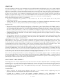
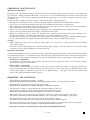
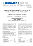
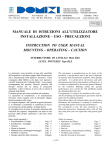
1
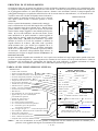
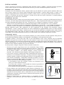
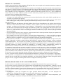
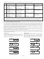
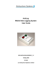
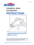
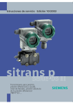
Indicatori di livello
Interruttori di livello
Strumenti pneumatici
DOMIZI Snc,
Te l +39-011-9457022
V ia Pole sine 15,
Fa x +39-011-9457021
Level indicators
Level switches
Pneumatic instruments
10020 CAMBIANO, TOR INO, ITALY
E -ma il : sa le [email protected]
w w w .domizi.com
M (DIL)
Settembre 05
MANUALE DI ISTRUZIONI ALL’UTILIZZATORE
INSTALLAZIONE – USO – PRECAUZIONI
INSTRUCTION TO USER MANUAL
MOUNTING – OPERATING – CAUTION
INDICATORI DI LIVELLO
LEVEL INDICATORS
Serie : DIL
Lo strumento viene prodotto in base alle specifiche
dell’acquirente e nel pieno rispetto delle Norme nazionali e internazionali sulla Qualità e Sicurezza. Viene
consegnato dalla fabbrica solo dopo aver superato i
controlli intermedi ed il collaudo finale; viene sempre
accompagnato dal presente Manuale generale, dal
Disegno tecnico che ne elenca le prestazioni
specifiche, e dal Certificato di prova che ne attesta il
collaudo individuale.
È pertanto pronto per essere installato sul serbatoio.
Le operazioni di installazione e di manutenzione
dovranno essere eseguite solo da personale adeguatamente preparato allo scopo.
Se vengono rispettati i dati riportati in questi documenti, lo strumento è certamente in condizione di assicurare prestazioni di alta qualità e di lunga durata.
Si consiglia perciò di porre la massima attenzione alle
istruzioni che seguono, integrandole con tutto ciò che
proviene dalla propria esperienza e dal buon senso
generale.
The instrument is manufactured on the basis of the
purchaser’s specifications and in the total conformity
of national and international standards about Quality
and Safety. It is delivered by the factory only after
having passed positively intermediate and final tests; it
is always accompanied by the present general Manual,
by the technical Drawing listing the specific
performances of it, and by the Test certificate stating
the individual final test of it.
Consequently it is ready to be installed on the vessel.
All the installing and maintenance operations shall be
made only by skilled personnel.
If purchaser effects the technical data reported in these
documents, the instrument is certainly in condition of
assuring high quality and long life performances.
We recommend to pay the max attention to the
following instructions, integrating them with all that
may come from your own experience and general good
sense.
Indice degli argomenti :
• Funzionamento e Targhe . . . . .
• Installazione : montaggio . . . . .
• Messa in funzione . . . . . . .
• Regolazione . . . . . . . . .
• Manutenzione: smontaggio/montaggio
• Problemi e soluzioni
. . . . .
• Disegno specifico dello strumento . .
Table of contents :
• Operation and Plates . . . . . .
• Installation : assembling . . . . .
• Start up
. . . . . . . . .
• Adjustment
. . . . . . . .
• Maintenance: dismantling/assembling
• Problems and solutions
. . . .
• Specific drawing of instrument . . .
.
.
.
.
.
.
.
Pag. 2
Pag. 3
Pag. 5
Pag. 5
Pag. 6
Pag. 6
Pag. 12
1 – M (DIL)
Page 7
Page 8
Page 10
Page 10
Page 11
Page 11
Page 12
PRINCIPIO DI FUNZIONAMENTO
Serbatoio
Gli Indicatori DIL sono progettati per indicare il livello del liquido contenuto in un serbatoio ed, eventualmente, dare
un segnale d’allarme quando viene raggiunta una certa altezza. Funziona sul principio della trasmissione magnetica
tra il galleggiante interno e la scala indicatrice esterna : durante i suoi movimenti verticali, il campo magnetico del
galleggiante interagisce con quello dei rullini bicolore che si trovano entro la scala indicatrice, e li fa ruotare di 180°.
A mano a mano che il livello del liquido sale nel serbatoio, i
Indicatore di Livello
rullini ruotano in modo da mostrare il lato rosso e nascondere quello bianco.Accade il contrario quando il livello
ridiscende.
Grazie a questo funzionamento, si hanno molti vantaggi :
Scala
(A) La trasmissione del livello dal liquido alla scala indicaindicatrice
trice è realizzata senza alcun contatto fisico. (B) Di conseguenza, anche se il liquido è sporco ed oleoso, la scala indiGalleggiante
catrice rimane sempre leggibile e non richiede pulizie perioFlange di
con magneti
attacco
diche. (C) La scala indicatrice non ha zone morte, né nei
tratti intermedi né in quelli terminali e risulta leggibile al
Allarmi
100% della sua altezza, anche da notevoli distanze e sotto
angoli molto ampi. (D) Sulla scala indicatrice è possibile
montare un Sensore di livello che trasmette a distanza un
segnale elettrico di 4÷20mA. (E) Sulla scala è possibile
Corpo
anche montare uno o più Allarmi per segnalare ad es. il
livello Max o Min o intermedio; è possibile aggiungerli
Flange di
anche in un secondo tempo, e modificare a piacere l’altezza
ispezione
di intervento. (F) Grazie alla possibilità degli allarmi, lo
strumento può svolgere la doppia funzione di Indicatore e di
Interruttore di Livello.
In questi strumenti il liquido sotto controllo ed i suoi vapori sono confinati nel corpo stagno anche quando sono sotto
pressione e ad alta temperatura, e non vengono mai a contatto né con l’esterno, né con la scala indicatrice : infatti la
trasmissione del movimento del galleggiante dal liquido alla scala indicatrice è affidata unicamente al campo
magnetico. Viene così annullato ogni rischio che si inneschino esplosioni di gas pericolosi.
TARGA SUGLI INDICATORI DI LIVELLO
SIGNIFICATO :
• Codice dello strumento
• Sigla assegnata dall’acquirente
• Num. serie dello strumento, Anno di produzione
• Pressione del fluido (massima o di progetto)
• Pressione e Data di collaudo
• Temperatura di Processo e Ambiente
• Peso specifico del fluido
• Volume del corpo strumento
• Allarmi elettrici : quantità
• Codice, Versione (antideflagrante, normale)
• Portata elettrica del contatto
• Marchio CE
• Ente Notificato che sorveglia la produzione
• Apparecchio per zone con atmosfera
potenzialmente esplosiva
• Gruppo II, Categoria 1/2
• Miscela esplosiva : Gas
• E = Norme europee armonizzate
• Ex = Protezione da rischio di esplosione
• dc = Custodia a prova di esplosione
a sicurezza costruttiva
• IIC = Gruppo dei gas / T… = Classi di temperature
• Ente Notificato : KEMA /Anno di certificazione 2005
• Numero di certificazione
• Versione senza allarme elettrico
• Nome e indirizzo del fabbricante
• Conforme alla normativa PED 97/23/CE
LEVEL INDICATOR
INDICATORE DI LIVELLO
Code : ____________
Tag : ______________
Serial No : ____________ Production year : ____
Pressure : _______ bar
Max
Project
Tested at : ______ bar, in date : ___/ ______
Proc.. T° min/max : ______ / ______ °C
Amb. T° min/max : ______ / ______ °C
Specific gravity of fluid : ______ kg/m³
Chamber volume : ____dm³
0948 PED
Electric alarms : ____ pcs
- Code _____
Version :
EEx d
Standard
- Load : As marked on the above Alarm switch
0496
II 1/2 GEEx dc IICT..
KEMA 05ATEX2124
(or II 1/2 G c T..)
(or 05ATEX2126)
www.domizi.com
[email protected]
Via Polesine 15
10020 Cambiano, Torino, Italia
Tel.+39 011 945.70.22 Fax +39 011 945.70.21
NOTA – Nel caso di Indicatore di Livello operante a temperature tali da costituire pericolo di scottature per la
persona, viene aggiunta una targa di avvertimento sullo strumento.
2 – M (DIL)
INSTALLAZIONE
Tutte le operazioni di ricezione e installazione dello strumento, anche se affidate a personale di lunga esperienza,
devono essere eseguite con i criteri della massima sicurezza, per evitare incidenti alle persone ed alle cose.
Disimballo dello strumento
Il trasporto fino alla destinazione finale, l’apertura della cassa di imballo ed il prelievo dello strumento dalla cassa
deve avvenire sempre con il criterio della salvaguardia dell’incolumità e sicurezza delle persone, e sempre e con
l’ausilio di appropriati mezzi di sollevamento, di guanti, occhiali, scarpe e vestiti previsti dalle Norme di Sicurezza.
Anche se lo strumento non presenta sporgenze o ruvidità tali da provocare tagli ed abrasioni, è normale prudenza
maneggiare tutto con molta cura e attenzione.
Collegamenti meccanici
Si raccomanda di operare sempre con la protezione di guanti, occhiali, scarpe e vestiti previsti dalle apposite Norme di
Sicurezza, e di usare sempre gli utensili più adeguati allo scopo. Tutte le operazioni dovranno essere eseguite solo da
personale adeguatamente preparato allo scopo. In particolare, per collegare lo strumento al serbatoio, bisogna :
- chiudere le valvole di intercettazione, in modo da interrompere il flusso del liquido da e verso il serbatoio;
- affacciare lo strumento ai punti di collegamento dell’impianto e poi fissarlo; si raccomanda di installarlo in
posizione verticale e ad almeno 1m di distanza da sorgenti elettromagnetiche, per evitare possibili interferenze.
Bisogna adoperare tiranti, dadi, guarnizioni ed altri componenti di tipo adeguato alle prestazioni richieste
dall’impianto, e serrare i tiranti sulle flange con chiave dinamometrica opportunamente tarata a seconda di quanto
richiesto dal costruttore delle flange. Bisogna operare con la massima attenzione e controllare infine anche la tenuta
dei collegamenti eseguiti, allo scopo di evitare il rischio di successive perdite di liquidi in pressione, corrosivi, o
caldi/freddi, e perciò potenzialmente pericolosi per la salute umana e per l’ambiente (esplosioni e incendi).
Collegamenti elettrici
Si raccomanda di operare sempre con la massima prudenza, per evitare pericolose scariche elettriche sulla persona e
anche danni potenzialmente ingenti sia all’impianto sia all’ambiente, come esplosioni ed incendi.
L’impianto elettrico, come d’altra parte tutto il resto dell’impianto, dovrà essere realizzato solo da personale
qualificato che agirà sul circuito solo dopo aver tolto tensione e dopo essersi accertato che nell’ambiente non vi è
atmosfera esplosiva; dovrà impiegare solo materiale certificato e adeguato alle esigenze dell’impianto (ad es. materiale
stagno, antideflagrante, etc). Una volta finiti i collegamenti, dovrà ripristinare le protezioni elettriche e meccaniche, in
modo da evitare contatti accidentali con parti sotto tensione.
Se sono presenti, collegare i dispositivi elettrici, facendo in modo che :
• Il Sensore di Livello venga fissato con le viti in dotazione lungo il fianco
dell’Indicatore DIL ed alla stessa altezza della Scala indicatrice. Nel caso di
collegamenti molto lunghi, si raccomanda di usare un cavo schermato con
fili di almeno 0,75mm² e con schermo collegato a massa ad una sola
estremità. Altre informazioni più dettagliate sono allegate al dispositivo.
• L’Interruttore magnetico venga fissato lungo i fianchi della Scala indicatrice
all’altezza a cui si desidera l’intervento; si tenga presente che il dispositivo
commuta quando il magnete del galleggiante passa in corrispondenza della
linea marcata “Switchpoint”. Il dispositivo racchiude un contatto reed, con 1
circuito in deviazione SPDT (Single Pole Double Throw) con le portate
elettriche elencate nella tabella della pag. seguente.
- Si raccomanda di usare fili di almeno 0,75mm² tra l’Interruttore ed il
carico, per evitare cadute di tensione.
- Se il carico non è resistivo, si raccomanda un circuito di protezione di
quelli mostrati nella pagina seguente.
- Si raccomanda un relé di protezione per allungare la vita all’Interruttore.
• Il carico elettrico non sia mai superiore a quello marcato sui dispositivi. Se è
possibile, si faccia in modo che l’intervento scatti sia quando il galleggiante
va nella posizione di intervento, sia nel caso che dovessero capitare eventuali
anomalie nel circuito elettrico (ad es. rottura del cavo, etc); in tal modo la
segnalazione sul quadro elettrico attirerà l’attenzione dell’operatore per una
riparazione più tempestiva.
• Durante le prime prove di collaudo elettrico si raccomanda di tenere
scollegati i circuiti utilizzatori, per evitare di provocare danni a persone ed a
cose.
3 – M (DIL)
SENSORE DI LIVELLO
Distanza
10mm tra
2 interruttori
Blu
Nero
Marrone
INTERRUTTORE
MAGNETICO
Schema elettrico
Blu
Nero
Marrone
Punto di commutazione
“Switchpoint”
L’ Interruttore magnetico fornito con l’Indicatore di Livello può essere uno delle seguenti versioni.
Tipo
1 Contatto SPDT bistabile
Corpo
Temperatura Conformità
Applicazioni
In argento, portata :
Ampolla reed in un corpo
+ 90°C max
Impianti con fluidi che non
• 2÷250Vac – 1A – 60VA
d’alluminio, cavo 1m in
formano miscele potenzial• 2÷250Vdc – 0,5A – 30W
PVC 3×0,75mm² + massa.
mente esplosive.
D2
Durata nominale :
Direttive :
• 10.000 manovre
Stagno IP65.
73/23/CEE + 93/68/CEE
In argento, portata :
Ampolla reed in un corpo
+ 150°C max
Impianti come sopra, ma
• 2÷250Vac – 1A – 60VA
d’alluminio, cavo Silicone
per temperature più elevate.
• 2÷250Vdc – 0,5A – 30W
3×0,75mm² + massa
D3
Durata nominale :
lunghezza 1m.
Direttive :
• 10.000 manovre
Stagno IP65.
73/23/CEE + 93/68/CEE
In argento, portata :
Ampolla reed in un corpo
+ 90°C max
Impianti con fluidi che
• 2÷250Vac – 1A – 60VA
d’alluminio, cavo 1m in
possono formare miscele
• 2÷250Vdc – 0,5A – 30W
PVC 3×0,75mm² + massa.
potenzialmente esplosive
D6
Durata nominale :
Stagno IP68
Direttive :
(*).
Antidefl. EEx dc IIC T6÷T3
• 10.000 manovre
73/23/CEE + 93/68/CEE
(*) – Negli impianti con rischio di esplosione viene impiegata anche la barriera a sicurezza intrinseca tra il contatto di allarme
ed il circuito utilizzatore, perché questa assorbe una corrente molto bassa (pochi milli-Ampere e pochi Volt) e tale da non
creare scintille pericolose e fonte di innesco efficace. In questo caso viene usato un allarme con contatto in oro, perché rimane sempre efficiente e affidabile (il normale contatto in argento potrebbe ossidarsi col tempo ed ostacolare il passaggio
delle bassissime correnti della barriera).
Come proteggere la durata di vita di un contatto elettrico
È noto che al momento dell’apertura o della chiusura delle pastiglie di un contatto elettrico (che può essere un interruttore, un
microswitch, un interruttore reed, etc) in certe applicazioni può scoccare una forte scintilla tra di loro. Se ripetuta nel tempo,
questa scintilla provoca prima un rapido aumento/deterioramento della resistenza di contatto, e poi una fine prematura di
funzionamento del contatto stesso, con due possibili esiti sulle pastiglie : o non si chiudono più (in realtà esse continuano a
toccarsi ma non conducono più la corrente elettrica, a causa dei tanti crateri scavati dalla scintilla) oppure non si aprono più
(perché saldate tra di loro a causa dell’alta temperatura dovuta alla scintilla e della pressione dovuta alla molla di scatto).
È anche noto che la scintilla è tanto più forte quanto più è induttivo o capacitivo il carico applicato al contatto elettrico. Pertanto,
per non accorciare eccessivamente la vita del contatto e compromettere così la sicurezza dell’impianto, si impone il rimedio di
limitare al massimo lo scoccare di tale scintilla. Suggeriamo qui di seguito alcuni accorgimenti.
I valori dei componenti da aggiungere sono da calcolare in base al carico elettrico da interrompere; alcuni di essi mirano ad
aumentare il cos ϕ dell’intero circuito al valore di 0,8-0,85 (rifasamento del circuito), altri ad assorbire l’energia che si
scaricherebbe sulle pastiglie mediante la scintilla.
Carico induttivo
Quando il carico è di tipo induttivo (motori, relé, bobine, tubi
fluorescenti non rifasati, etc), suggeriamo di inserire uno dei
seguenti circuiti di protezione, per limitare l’extra-tensione e
la conseguente scintilla che si avrebbe all’apertura delle
pastiglie.
Carico capacitivo
Quando il carico è di tipo capacitivo (condensatori,
alimentatori switching, lampade a filamento ed alogene,
etc), suggeriamo di inserire uno dei seguenti circuiti di
protezione, per limitare la forte corrente iniziale e la
conseguente scintilla che si avrebbe alla chiusura delle
pastiglie.
~
~
Vac
Vac
R
C
R
~
~
~
~
L
Vac
Vac
R
R
C
~
~
~
~
Vac
L
R
Vac
Lampada
Varistor
~
~
+
~
Lampada
Vac
Vdc
Diodo
R
~
4 – M (DIL)
MESSA IN FUNZIONE
Anche la messa in funzione dello strumento sull’impianto deve essere eseguita con la massima attenzione, sempre per
evitare incidenti alle persone e danni alle cose.
Avviare con molta gradualità il riempimento dello strumento con il liquido da controllare facendo la max attenzione a
non superare i valori di Pressione e di Temperatura indicati nel progetto dell’impianto e riportati nei dati di Targa dello
strumento e nel Disegno specifico che lo accompagna. In tal modo si avrà la possibilità di intervenire in tempo nel
caso di qualche svista nei collegamenti, e di evitare quindi rischi di danni a persone ed a cose. Sono comunque da
evitare colpi di ariete sullo strumento, perché se fossero molto forti, potrebbero provocare malfunzionamenti, e nei
casi limite il blocco completo dello strumento.
Durante l’avviamento dell’impianto si raccomanda di :
• Avvicinarsi con molta cautela allo strumento: può contenere liquidi molto caldi o molto freddi, e quindi può causare delle serie scottature alle persone.
• Aprire con cautela le valvole di spurgo e di sfiato dello strumento : possono uscire liquidi corrosivi, molto caldi o
molto freddi, oppure sotto pressione, e quindi potenzialmente pericolosi per l’uomo e per l’ambiente.
Note importanti :
• Durante il trasporto dell’Indicatore DIL dalla fabbrica fino al luogo di installazione, può capitare che nella Scala
Indicatrice alcuni elementi bi-colorati (cilindretti o alette) vadano a girarsi in una posizione diversa da quella
originale; avrebbero perciò bisogno di essere riallineati. L’allineamento avverrà in modo automatico durante la
fase del primo caricamento totale del liquido nell’Indicatore, quando cioè il galleggiante farà l’intera corsa verso
l’alto; se ciò non dovesse bastare, è sufficiente far scorrere un piccolo magnete lungo il fianco della Scala
Indicatrice, prima dal basso verso l’alto (tutti gli elementi diventano rossi), e poi viceversa (tutti gli elementi
diventano bianchi).
• Se sono presenti degli Interruttori magnetici, sarà necessario fare la stessa operazione di sopra per riportare alla
posizione di riposo i contatti bistabili SPDT interni.
• Se è presente il Sensore di Livello, non è necessario fare alcuna taratura : il valore totale della resistenza
(quello misurato tra il filo Blu e quello Nero) è prefissato in fabbrica, mentre il valore parziale (tra il Blu e
Marrone, oppure tra il Marrone e Nero) varia in funzione dell’altezza raggiunta dal galleggiante.
Cosa capita in caso di incendio ? Lo strumento è costituito principalmente di metallo e pertanto non può essere fonte
primaria di incendio; ed inoltre, quando richiesto dall’acquirente, vengono forniti strumenti in versione certificata
ATEX antideflagrante. Nel caso però che l’incendio provenisse dall’ambiente esterno, lo strumento in sé non subisce
danni significativi. Vi è solo una raccomandazione all’installatore dell’impianto elettrico : se il progetto e l’ambiente
circostante comporta il rischio potenziale di esplosioni o di incendio, allora è indispensabile l’impiego di
apparecchiature e condutture elettriche in versione antideflagrante e con ritardo di propagazione di fiamma.
Lo strumento è stato realizzato con ampi margini di sicurezza, in modo che possa svolgere egregiamente i compiti
comunicati dal committente alla Domizi Snc, anche in caso di lievi sovraccarichi in pressione e temperature, purché
rientranti nei limiti previsti dalle Istruzioni di Collaudo delle Norme ASME/ANSI. Di norma si prevede la messa in
opera sul serbatoio di due Allarmi, in modo che il primo esegua il normale lavoro di controllo (ad es. intervento per
Livello Alto), ed il secondo intervenga al posto del primo in caso di avaria (ad es. allarme per Livello Altissimo).
Se però, in seguito ad errori di manovra nella gestione dell’impianto, lo strumento venisse sottoposto a colpi improvvisi di pressioni e di temperature con valori totalmente al di fuori di quelli previsti dalle Norme ASME/ANSI,
potrebbe nascere il rischio di un suo cedimento strutturale; per evitare questo cedimento ed altre conseguenze ancora
più gravi al resto, il progettista dell’impianto realizza un adeguato sistema di protezione.
REGOLAZIONE DEL PUNTO DI INTERVENTO
La Scala indicatrice non richiede alcuna regolazione, se non quella descritta nelle Note importanti poco sopra..
Gli Interruttori magnetici possono essere spostati molto agevolmente lungo la Scala indicatrice : allentare la vite di
fissaggio e spostare l’Interruttore fino all’altezza a cui si desidera avvenga l’intervento (si tenga presente che il
dispositivo commuta quando il magnete del galleggiante passa in corrispondenza della linea marcata “Switchpoint”);
riavvitare infine la vite di fissaggio. Questa operazione può essere ripetuta fino a trovare il giusto punto di lavoro.
Osservazioni :
• Il galleggiante è tarato per il liquido con il peso specifico indicato nell’ordine; se viene impiegato con
liquidi diversi, il galleggiante può indicare un livello anche abbastanza diverso dal reale.
• Se il liquido ha tendenza a ricoprire il galleggiante (ad es. sostanze paraffiniche a basse temperature), può
capitare di leggere, col passare del tempo, un livello abbastanza più basso del reale.
5 – M (DIL)
MANUTENZIONE PERIODICA
Manutenzione meccanica
Nel tempo può rendersi necessaria una pulizia periodica dell’interno del corpo dell’Indicatore, per liberarlo da
eventuali residui e incrostazioni liberati del liquido sotto controllo; tale pulizia può essere eseguita indicativamente
1-2 volte all’anno, a seconda del tipo di liquido. Si dovrà procedere nelle varie fasi con la massima attenzione, per
evitare di correre rischi per la salute delle persone (scottature, intossicazioni, etc) e per la salvaguardia dell’ambiente
(esplosioni, incendi, etc).
In ogni caso, dopo aver indossato guanti, occhiali e vestiti adeguati, bisogna smontare lo strumento con queste fasi :
• Chiudere le valvole che intercettano l’entrata e l’uscita del liquido dallo strumento.
• Se necessario, attendere che l’intero strumento sia tornato alla temperatura ambientale, per evitare scottature.
• Aprire con molta cautela la valvola di drenaggio inferiore e, se presente, quella di sfiato superiore, badando a
ripararsi da eventuali spruzzi del liquido interno perché può essere corrosivo e pericoloso.
• Svitare i dadi dai tiranti delle flange, e staccare con delicatezza lo strumento dall’impianto.
• Svitare i dadi dai tiranti della flangia di ispezione e sfilare il galleggiante.
• Con l’aiuto di getti d’aria compressa, di vapore, etc, effettuare la pulizia interna dello strumento e del galleggiante,
liberandoli da ogni possibile incrostazione; verificare anche che il galleggiante sia integro, che cioè non presenti
deformazioni o perdite.
• Rimontare il tutto, procedendo nella sequenza di sopra, ma nel senso contrario, ved. INSTALLAZIONE a pag. 3.
• Riavviare l’impianto, come descritto nel par. MESSA IN FUNZIONE a pag. 5.
Attenzione :
- Nell’infilare nuovamente il galleggiante entro il corpo dell’Indicatore bisogna sistemare verso l’alto
l’estremità marcata “Top - Oben - Sopra”.
- Il galleggiante è in grado di sopportare variazioni di pressione abbastanza graduali; se invece viene sottoposto a
variazioni molto brusche, può subire danni anche molto gravi, fino alla completa distruzione.
Manutenzione elettrica
Per evitare pericolose scariche elettriche sulla persona e anche danni potenzialmente ingenti all’impianto ed anche
all’ambiente (esplosioni ed incendi), si raccomanda di agire con la massima prudenza e sempre dopo aver staccato la
tensione elettrica dal circuito ed essersi accertati che nell’atmosfera non ci siano miscele di gas esplosivi.
• Sensore di livello : sostituzione
A seguito dell’usura di qualche organo interno, può essere necessaria la sostituzione del Sensore. Bisogna seguire
le istruzioni allegate al dispositivo.
• Allarme elettrico : sostituzione
A seguito dell’usura del contatto elettrico interno, può essere necessaria la sostituzione dell’Allarme elettrico.
Questo viene dato dalla casa costruttrice con una durata indicativa di 10.000 manovre con carico elettrico nominale
(ved. tabella di pag. 4); ma tale durata può accorciarsi notevolmente se il carico elettrico è più alto di quello
nominale oppure se è induttivo o capacitivo (ved. par. Come proteggere la durata … a pag. 4). Le operazioni da
fare sono le stesse esposte nel par. INSTALLAZIONE a pag. 3.
procedere come per l’INSTALLAZIONE descritta a pag. 3.
PROBLEMI E SOLUZIONI
• Il liquido non solleva il galleggiante, oppure lo sommerge.
- Forse lo strumento va sistemato ad un’altezza diversa sul serbatoio, oppure non è perfettamente verticale.
• Il liquido è a livello sufficiente, ma non aziona il galleggiante.
- Forse il galleggiante è danneggiato (forato o deformato) : occorre sostituirlo.
• Il galleggiante si muove regolarmente, ma la Scala indicatrice non mostra cambiamenti di livello.
Il galleggiante si muove regolarmente, ma gli Allarmi montati sulla Scala indicatrice non scattano.
- Forse i magneti all’interno del galleggiante si sono smagnetizzati : occorre sostituire il galleggiante.
• Scatta l’Allarme di “Livello Alto” quando il liquido è basso, e di “Livello Basso” quando il liquido è alto.
- I collegamenti elettrici sono errati : bisogna invertirli; ved. Collegamenti elettrici pag. 3.
• L’Allarme non commuta oppure, anche se commuta, il segnale elettrico in uscita è assente.
- L’interruttore interno è rotto e occorre sostituirlo : ved. INSTALLAZIONE a pag. 6.
• Il Sensore di livello non dà alcun segnale elettrico o lo dà in modo non corrispondente al livello del liquido.
- Il Sensore è rotto e occorre sostituirlo : ved. INSTALLAZIONE a pag. 6
• In caso di necessità di una riparazione, preghiamo interpellare direttamente la sede della Domizi Snc.
6– M (DIL)
OPERATION PRINCIPLE
Vessel
The DIL Indicator has been designed to show the level of a liquid contained in a vessel and, possibly, give an alarm
signal when a certain height is reached.
They work on the magnetic transmission principle between
the inner float and the outer display : during its vertical
Level Indicator
movements, the magnetic field of float interacts with that of
the two-coloured rollers being inside the display, and makes
them rotates of 180°. As level rises, the rollers rotate so that
show their red side and hide their white side. The contrary
Dial
happens when level comes down again.
Thanks to this way of working, many advantages arrive :
Float with
(A) The transmission of level from liquid to display is made
Connection
magnets
by agnetic field, i.e. without any physical contact. (B)
flanges
Consequently, even if liquid is dirty and oily, the display is
always legible and needs no periodic cleanings. (C) The
Alarms
display has no dead zones and can be read on the 100% of
its height and under wide angles. (D) It is possible to mount
on the display a Level Sensor able to remote transmit an
Body
electric 4-20mA signal. (E) It is possible to mount on the
same display one or more Alarms that may trip for example
at max, min or intermediate level; it is also possible to add
Inspection
flanges
them in a second time, and to change the trip height at will.
(F) Thanks to the alarms possibility, the instrument can
perform a double function : as Indicator and as Switch.
In these instruments the liquid to be controlled and its fumes are confined to their sealed space even when are under
pressure and high temperature, and do not come to contact neither with outside nor with the housing that includes the
output device (Dial, Alarms, Sensor, etc) : in fact the float motion transmission from liquid to output device is assigned
only to magnet field. In this way every possible explosion risk of dangerous gas are totally excluded.
TARGA SUGLI INDICATORI DI LIVELLO
MEANING :
• Instrument code
• Tag assigned by purchaser
• Serial No., Year of production
• Pressure of fluid (highest/design)
• Pressure and Date of test
• Proc and Amb Temperature
• Specific gravity of fluid
• Volume of instrument chamber
• Electric alarms : quantity
• Code, Version (anti-flame, standard)
• Electric load of contact
• CE Mark
• Notified Body supervising production
• Equipment for areas with atmospheres
potentially explosive
• Group II, Category 1/2
• Explosive mixture : Gas
• E = Harmonized European standards
• Ex = Protection from explosion risks
• dc = Safety constructive flame-proof housing
• IIC = Gas groupe / T… = Temperature class
• Notified Body : KEMA / Certificate year : 2005
• Certificate number
• Version without Electrl alarms
• Name and address of manufacturer
• In accordance to PED 97/23/CE
LEVEL INDICATOR
INDICATORE DI LIVELLO
Code : ____________
Tag : ______________
Serial No : ____________ Production year : ____
Pressure : _______ bar
Max
Project
Tested at : ______ bar, in date : ___/ ______
Proc.. T° min/max : ______ / ______ °C
Amb. T° min/max : ______ / ______ °C
Specific gravity of fluid : ______ kg/m³
Chamber volume : ____dm³
0948 PED
Electric alarms : ____ pcs
- Code _____
Version :
EEx d
Standard
- Load : As marked on the above Alarm switch
0496
II 1/2 GEEx dc IICT..
KEMA 05ATEX2124
(or II 1/2 G c T..)
(or 05ATEX2126)
www.domizi.com
[email protected]
Via Polesine 15
10020 Cambiano, Torino, Italia
Tel.+39 011 945.70.22 Fax +39 011 945.70.21
NOTE - In the case of Level Indicator operating at temperatures such that may cause burns on persons, an
adjunctive plate is fixed on the instrument, in order to caution about the possible risk.
7 – M (DIL)
INSTALLATION
Every operations regarding receipt and installation of instrument, even if assigned to long experienced personnel,
shall be made with the norm of the maximum security, to avoid accidents to persons and things.
Instrument unpacking
Transport up to final destination, case opening and picking up of instrument from the case shall be made always with
the norm of protection and safety of persons, and always with the help of proper lifting means, of gloves, glasses,
shoes and clothes recommended by Safety Standards. Even if instruments have no protrusion or roughness, able to
cause wounds and abrasions, it is recommended to handle everything with the highest care.
Mechanical connections
We recommend to operate always with the protection of gloves, glasses, shoes and clothes listed by Safety Standards,
and by using the most proper tools. Every operations shall be made only by skilled personnel. In particular, to
connect the instrument to vessel, it is necessary :
- to shut off the cocks, in order to stop the flow from and to vessel;
- to put the instrument forward the connection points of the system and then to fix it; we recommend to install it so
that housing remains in vertical position and at least at 1m far from electromagnetic sources, to avoid possible
disturbs and interferences.
It is necessary to use tie-rods, nuts, gaskets and other components absolutely suitable for the performances needed by
the system, and to tighten tie-rods on flanges with a dynamometric wrench, correctly calibrated according to the
instructions of flange’s manufacturer. It is also necessary to operate with the max attention and to check the seal of
these mechanical connections, in order to absolutely avoid the risk of subsequent liquid leaks : they may be under
pressure or corrosive or too cold/hot, and so may be potentially dangerous for human health and for environment
(fires and explosions).
Electric connections
We recommend to operate with the highest prudence, to avoid dangerous electric shocks on people and potentially
huge damages both on system and on environment, as explosions and fires.
The electric system, in the same way as other types of systems, shall be realized only by skilled personnel and only in
absence of tension on electric line and in absence of potentially explosive atmospheres, and will be made only by using
components being certified and suitable for the plant (e.g. explosion-proof or water-proof materials certified, etc).
After having made connections, it is necessary to restore the mechanical and electric protections, in order to
absolutely avoid casual contacts with parts under tension.
If they are present, connect the electric devices, so that :
LEVEL SENSOR
• The Level Sensor be fixed with the equipped screws along the side of
Indicator and at the same height as the Dial. In the case of very long
connections, it is advisable to use a sheathed cable, with wires of at least
Distance
0,75mm² and earthed at one end only. Further information is enclosed to
10mm
the device.
between
2 switches
• The Magnetic switch be fixed with the equipped screws along the side of
Dial at the heights corresponding to max and min level operations, or to
other types of operations; remember that the switch operates when the
magnet inside the float passes nearby the “Switchpoint” line. The device
Blue
Black
includes a reed contact with a SPDT circuit (Single Pole Double Throw)
Brown
with the loads listed in the following page.
- We recommend to use wires of at least 0,75mm between the Switch and
the load, to avoid voltage drops.
MAGNETIC SWITCH
- If load is not resistive, we recommend a protection circuit by choosing it
among those listed on the following page.
Electric diagram
- We recommend to use a protection relay, to protect the life of the alarm
switch
• The electric load never be higher than that marked on the electric devices. If
possible, try to obtain an alarm both when float touch the trip height, and
also in the case accidents might happen in the electric circuit (for ex. cable
Blue
Black
breakage, etc); in this way the alarm on the panel will catch the operator’s
Brown
attention for a quicker repair.
Switchpoint line
• During the first electric tests, the user circuits should be unconnected, to
avoid harm to persons and to goods.
8 – M (DIL)
The Magnetic alarm switch supplied with the Level Indicator can be one of the following versions.
Type
1 Contact SPDT bistable
Enclosure
Temperature Conformity
Applications
Silver, load :
Glass reed within alumi+ 90°C max
Systems with fluids forming
• 2÷250Vac – 1A – 60VA
nium case, PVC cable 1m,
mixtures of gas
• 2÷250Vdc – 0,5A – 30W
3×0,75mm² + earth.
not potentially explosive.
D2
Nominal life :
Directives :
• 10.000 operations
Water-proof IP65.
73/23/CEE + 93/68/CEE
Silver, load :
Glass reed w/in aluminium + 150°C max
Systems as above, but
• 2÷250Vac – 1A – 60VA
case, Silicon cable 1m,
for higher temperatures.
• 2÷250Vdc – 0,5A – 30W
3×0,75mm² + earth
D3
Nominal life :
Directives :
• 10.000 operations
Water-proof IP65.
73/23/CEE + 93/68/CEE
Silver, load :
Glass reed within alumi+ 90°C max
Systems with fluids forming
• 2÷250Vac – 1A – 60VA
nium case, PVC cable 1m,
mixtures of gas
• 2÷250Vdc – 0,5A – 30W
3×0,75mm² + earth.
potentially explosive. (*)
D6
Nominal life :
Water-proof IP68
Directives :
Flame-prof EEx dc IIC T6÷T3
• 10.000 operations
73/23/CEE + 93/68/CEE
(*) – In the systems with risks of explosion also intrinsic safety barrier is used between the alarm contact and the user circuit,
as it absorbs a very low current (a few milli-Amperes and few Volts) and such that no dangerous spark and no effective
explosion source can be created. In this case alarm with gold contact is preferable, because it remains always efficient
and reliable (the normal silver contact could oxidize after time and could stop the very low current of the barrier).
How to protect the life of an electric contact
As everybody knows, at the moment of opening or closing of an electric contact (of a switch, microswitch, reed switch, etc) in
certain applications a strong spark may happen between the two elements of the contact. If repeated in the time, this spark causes
in the first stages a quick worsening/increase of contact resistance, and then an untimely work ending of the same contact, with
two possible results on the elements : or they close no longer (in reality they touch themselves, but conduct electric current no
longer, because of so many craters dug by the spark), or they open no longer (as welded between themselves because of the high
temperature of the spark, and of the high pressure of the release spring).
We know also that the spark becomes stronger as the load connected to the electric contact becomes more inductive or capacitive.
Therefore, in order not to shorten the contact life too much, and not to compromise the system safety, it is necessary and advisable
to limit the spark priming as much as possible. We expose here some solutions.
The components values are to be calculated on the base of electric load to be switched off; some of them aim to increase cos ϕ of
the whole circuit up to 0,8-0,85 (power factor correction), other of them aim to absorb the energy that would discharge by means
of spark onto the elements of contact.
Inductive load
When the load is inductive (motors, relays, coils, etc), we
suggest one of the following protection circuits, in order to
limit the extra-voltage and the consequent spark that would
happen at the contact opening.
Capacitive load
When the load is capacitive (capacitors, switching supplies,
filament and halogen lamps, etc), we suggest one of the
following protection circuits, in order to limit the strong
inrush current and the consequent spark that would happen
at the contact closing.
~
~
Vac
Vac
R
C
R
~
~
~
~
L
Vac
Vac
R
R
C
~
~
~
~
Vac
L
R
Vac
Lamp
Varistor
~
~
+
~
Lamp
Vac
Vdc
Diode
R
~
-
9 – M (DIL)
START UP
Also the operations of starting up of instrument on system shall be made with the highest care, just to avoid accidents
to people and to things. In particular, we highly recommend to start very gradually the loading of instrument with the
liquid to be controlled, by paying the highest attention not to exceed the max values of Pressure and Temperature
reported on the Project of system, on the instrument Plate and on the specific Drawing accompanying the instrument.
In these way the operator is in condition of immediately intervening in case of any mistake and thus avoid risks of
damages to people and to things. In any case water hammers on the instrument are absolutely to be avoided : if too
strong, they might cause uncertain functions and in the most severe cases also a total blocking of it.
During the normal function of plant, we recommend :
• To get near instrument very prudently : it may contain very hot or very cold liquids, and so may cause
serious burns to people.
• To open drain and vent valves of instrument with much caution : very dangerous liquids may come out (as very hot,
very cold, corrosive or under pressure) and may cause damages to people and to things.
Important notes :
• During the carriage of DIL Indicator from factory to destination, it may happen that in the Display some bicoloured rollers may rotate to a position being different than the original; they should be reset. This operation
will be automatically done during the first total loading/unloading of liquid into Indicator, when the float will run
the entire stroke up/downwards; in the case it would not be enough, it is sufficient to slide a small magnet along
the side of display, first from bottom to top (the elements become red), then on the contrary (they become white).
• If Magnetic Switches are installed, the same above resetting operation will be perhaps necessary to reset the
bi-stable SPDT contacts.
• If Level Sensor is installed, no resetting operation is necessary : the total resistance value (measured between Blue
and Black wire) is pre-set in the factory, while the partial value (Blue-Brown, or Brown-Black) changes in
proportion of the height touched by the float.
What happens in case of fire ? The instrument is composed mainly by metal and so cannot be primary source of fire,
and furthermore, when requested by purchaser, instruments are supplied in ATEX certified flame-proof version. But
in the case that fire comes from outside environment, the instrument does not suffer significant damages. Only a
recommendation to electric wiring installer : in the case the environment involves the risk of explosions or fires, then
it is absolutely necessary to use devices and pipes in explosion-proof and/or flame retardant version.
The instrument has been realized with wide safety margin, so that can certainly assure the performances requested by
purchaser to Domizi Snc, even in the case of slight overloads in pressure and temperatures, on condition that they
come under the limits listed in the Test Instructions of ASME/ANSI standards. In the usual cases two alarms are used
on the same vessel, so that the first one performs the normal control function (e.g. High level operation), and the
second one operates in case of breakdown of the first one (High-High level alarm).
But in the case of important mistakes in process management, the instrument might be subject to sudden peaks of
pressures and temperatures having values totally out of those listed in the ASME/ANSI standards, it might be subject
to structural damages; just in order to avoid this damage and other much heavier effects on the remaining parts, the
plant designer realizes a proper and effective protection system.
SNAP POINT ADJUSTMENT
The Display does not need any adjustment, unless that described in the above Important Notes. The Magnetic alarm
switches can be very easily moved along the Display side : loosen the fixing screw and move the switch until the
desired height is achieved (would you please consider that the device operates when the float magnet passes in
correspondence of “Switchpoint” line); then tighten the fixing screw again. This moving can be repeated until the
correct height is found.
Considerations :
• Float is rated for the specific gravity showed in the order; if it is actually used for a different gravity, the
float may indicate a level being also quite different than the real one.
• If liquid has a tendency to cover (for example, paraffinic substances at low temperatures), it may
happen that the float becomes heavier, and so Indicator may show a level much lower than the real one.
10 – M (DIL)
PERIODICAL MAINTENANCE
Mechanical maintenance
During the time a periodical cleaning of inside instrument from possible deposits may be necessary; according to the
type of liquids, cleaning could be made about 1-2 times a year. It is recommended to proceed in the various steps with
the highest care, to avoid risks for health of people (burns, poisonings, etc) and for environment protection (fires,
explosions, etc).
In any case, after having put on gloves, glasses and suitable clothes, would you please :
• Shut off the inlet and outlet cocks, in order to block the liquid to and from the instrument to be checked.
• If necessary, wait until the instrument come back to environmental temperature, to avoid burns.
• Open with much prudence the bottom drain valve and, if present, the top vent one, taking care to avoid splashes of
inner liquid because potentially corrosive and dangerous.
• Unscrew the nuts from the connection flanges, and remove the instrument from system with much care.
• Unscrew the nuts from the inspection flanges, and unslip the inner float.
• With jets of compressed air, of steam, etc, make the inner cleaning of instrument and of float, removing every
possible encrustments; then check that float is intact, i.e. without deformities or splits.
• Re-assemble everything, by proceeding in the above sequence, but on the contrary, as per INSTALLATION page 8.
• Fill very prudentially the instrument with the liquid and start up it, as per START UP on page 10.
Warning :
- While slipping the float into the Indicator body again, it is necessary to place upwards the end marked
“Top - Oben - Sopra”.
- The float is able to withstand pressure variations being rather gradual; if on the contrary it is exposed to sharp
variations, it may be heavily damaged, and also destroyed.
Electrical maintenance
In order to avoid dangerous electric shocks to people, and also potentially huge damages to the plant and environment
too (explosions and fires), we recommend to act with the highest prudence and always after having turned off electric
voltage from the circuit and after having ascertain absence of potentially explosive gas mixtures in the atmosphere.
• Level Sensor : replacement
In consequence of wear of some inner element, it may be necessary to replace the Sensor. It is necessary to follow
the instruction supplied with the device.
• Electric alarm : replacement
In consequence of wear of the inner contact, it may be necessary to replace the Sensor. It is given by producer for
a life of 10.000 operations at nominal load (as per table on page 9); but this life may be remarkably shorter if the
electric load is higher or inductive or capacitive (as per How to protect ... on page 9). The due operations are the
same as described in INSTALLATION on page 8.
PROBLEMS AND SOLUTIONS
•
•
•
•
•
•
•
The liquid does not push float upwards, or sink it.
Maybe the instrument should be placed at a different height on vessel, or is not perfectly vertical.
The liquid is at sufficient level, but does not push the float.
Maybe the float is damaged (cracked or deformed) : it should be replaced.
The float moves regularly, but the Display does not show changes in the level.
The float moves regularly, but the Alarms placed on the Display do not trip.
Maybe the magnets inside the float are exhausted : the float is to be replaced.
When liquid is low, the output electric signal lights “High Level”, and when high lights “Low Level”.
The electric connections on the terminal are incorrect : it is necessary to reverse them; as per page 8.
The Alarm does not trip or, even if trips, the output electric signal is absent.
The inside switch is failed and is to be replaced : as per INSTALLATION on page 8.
The Level Sensor does not give any electric signal, or give a signal not corresponding to the level of liquid.
The Sensor is failed and is to be replaced : as per INSTALLATION on page 8.
If a repair is necessary, would you please contact the seat of Domizi Snc directly.
11 – M (DIL)