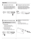
1
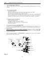
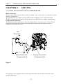
USER’S MANUAL “PRIMA” Release: 4.8 October 01st, 2012 WARNING WARNING This machine has been built according to the appropriate safety rules, as required by law. The user must fulfil all safety requirements concerning the use and maintenance of the machine. LCM shall not be considered responsible for damages to people or things caused by incorrect or inappropriate use of the machine. The user must also ascertain that the pressing operation is performed adequately and its results correspond to the expected technical and esthetical requirements. It remains the user’s responsibility to verify that the product of the pressing operation is according to the standards requested. LCM may cooperate with the user who needs specific parts to enhance the quality of the operation (for example by manufacturing, if requested, specific tools and frames to carry out particular operations). LCM may modify the software or the manual of this machine without giving prior communication. 2 PREFACE PREFACE The scope of this manual is to teach the operator about the use of this machine, regarding its transport, handling, installation, setting, operation and maintenance. This manual must be kept, for reference, near the machine or in a place easily retrievable. It must be kept in a proper place, avoiding humid environments, and good care must be taken to avoid its deterioration. For other copies, updated copies or further information, please contact: LCM Via Martino Ferraro, 3 - 54100 MASSA ITALIA email: [email protected] Figure 1 shows CE markings, as reported on the machine tag. Figure 1 3 INDEX PART 1: DESCRIPTION OF THE MACHINE __________________________ CHAPTER 1: TECHNICAL FEATURES _____________________________ 1.1) Overview ________________________________________________ 1.2) How it works______________________________________________ 1.3) Field of application_________________________________________ 1.4) Materials which may be used_________________________________ 1.5) Power requirements_________________________________________ 1.6) Operating environment______________________________________ 1.7) Operator’s workplace_______________________________________ 1.8) Operator’s requirements_____________________________________ 1.9) Description of commands____________________________________ 1.10) Noise____________________________________________________ 1.11) Technical data _____________________________________________ CHAPTER 2: SAFETY ___________________________________________ 2.1) Compressed air switch-off device _____________________________ 2.2) Hazards __________________________________________________ 2.3) Misuse___________________________________________________ 2.4) Max. sheet dimensions and weight ____________________________ PART 2: INSTALLATION, SETTING AND OPERATION___________________ CHAPTER 3: INSTALLATION _____________________________________ 3.1) Packaging ________________________________________________ 3.2) Handling _________________________________________________ 3.3) Preliminary checking________________________________________ 3.4) Storing before unpacking ____________________________________ 3.5) Storing after unpacking _____________________________________ 3.6) Disposal of packaging ______________________________________ 3.7) Checking after unpacking ___________________________________ 3.8) Installation of the machine on its standard base 3.9) Installation of the machine without its standard base ___________ 4 INDEX CHAPTER 4: SETTING____________________________________________ 4.1) Connection to mains and to compressed air ____________________ 4.2) Preliminary checking_______ _________________________________ CHAPTER 5: HOW TO OPERATE THE MACHINE 5.1) Electronic functions _______________________________________ 5.2) Adjustments and settings ___________________________________ 5.3) Inserting of self-clinching fasteners with the machine in its standard configuration ____________________________________ ________ 5.4) Inserting of self-clinching fasteners in other configurations (Accessory 1 and Accessory 2)___________________________________________ PART 3: MAINTENANCE CHAPTER 6: MAINTENANCE ___________________________________ 6.1) Overview ________________________________________________ 6.2) Daily maintenance _________________________________________ 6.3) Use of the TEST menu______________________________________ ATTACHMENT No 1: ELECTRIC DIAGRAM ATTACHMENT No 2: PNEUMATIC DIAGRAM 5 PART 1: DESCRIPTION OF THE MACHINE 6 CHAPTER 1: 1.1) TECHNICAL FEATURES OVERVIEW This manual contains instructions for installation, use and maintenance of the PRIMA press. The manual is intended both for the operators and for the trainers of the operators. The original of this publication, written in Italian, is a unique reference for the resolution of any disputes related to the interpretive translations in European languages. This publication is also an integral part of the machine and therefore must be preserved for future reference until the final demolition of the machine. SCOPE OF THE MANUAL The scope of this manual is to teach operators how to safely use the machine. Uses of PRIMA that differ from those herein specified are prohibited. The user must also comply with work legislation in force in the country where the machine is operated. HOW TO KEEP THE MANUAL This manual must be kept in a protected and dry place, near the machine, to allow quick consultation. It is also advisable to make a copy of this manual, as a back-up. When consulting the manufacturer for any question about the machine, always quote model and serial number of the machine you own / use. This manual must be kept for all the life of the machine; should it deteriorate, ask the manufacturer for a new copy. UPDATING OF THE MANUAL The instructions contained here have been prepared according to the laws in force at the date of release of the machine on the market. The current manual cannot be considered inadequate because of later updating determined by new rules or by other needs. Possible modifications, adaptations, enhancements and the like that should be made on machines sold afterward, do not oblige the manufacturer to modify machines formerly sold, nor justify considering the machine or the manual lacking or inadequate. Possible additions to this User’s Manual that the manufacturer would send to users, are to be considered integral part of the manual itself and shall be kept together with the original manual. PART 1 DESCRIPTION OF THE MACHINE COOPERATION WITH THE USER The manufacturer may be contacted for further information and will consider proposals and hints to improve this manual. If the machine is sold or given to a third party, this manual must accompany it. In this case, the original owner/user is required to send the new owner’s/user’s address to the manufacturer; in this way, the manufacturer shall be able to contact the new user for any updating or communications needed. WARRANTY The warranty duration is: 1 year The user must strictly follow the indications given in this manual, to avoid invalidating the warranty. In particular, he shall always: Operate the machine within the specified limits Make a careful daily maintenance Employ people adequately trained and who have proven skill and attitude for this kind of job. The manufacturer disclaims any liability deriving from: Failure to observe the instructions. Uses of the machine different from those specified in this manual. Use of the machine by people who have not read and understood this manual. Uses of the machine that go against the relevant laws of the country where the machine is operated. Modifications on the machine not authorized by the manufacturer Repairs by unauthorised people Use of spare parts and accessories that are not original The warranty is invalidated if, when selling the machine to a third party, one omits furnishing the new user with this manual as well. Should the new user be from a country where a different language is spoken, it will be the original owner’s responsibility to give him an accurate and faithful translation of this manual, in the user’s language. TECHNICAL ASSISTANCE For any kind of repair and servicing not described in the manual, please contact the manufacturer, at the following address: LCM S.r.l. – Via Martino Ferraro, 3 54100 Massa (MS) – ITALY email: [email protected] 8 PART 1 1.2) DESCRIPTION OF THE MACHINE HOW IT WORKS PRIMA LCM is a press for self-clinching fasteners, which must be employed on products obtained from metal or plastic sheets. Being cost-effective, flexible, compact, easy to use and to maintain, this machine is very attractive to anyone working with metal sheets. A sturdy metal frame, containing inside all the leverage to operate the pressing, constitutes the main body. It also accommodates a carriage that supports the anvil holder. The anvil can be replaced according to the type of fastener to be fitted. Movements are obtained by a double-effect pneumatic cylinder operating a lever, which presses the punch, inserting the fastener. A device that blocks the piece between punch and anvil with a force of 15 Kg. makes inserting easier, more accurate and safer. The body of the machine, which support also the electronics cabinet, is placed on a sturdy steel structure that can be fixed either on the original base (optional) or on a adequately strong and stable bench (figure 2). 1.3) FIELD OF APPLICATION The machine is intended exclusively for the insertion of self-clinching fasteners, on materials having the requisites specified in the next paragraph. The manufacturer disclaims any liability for uses of the machine not specified in this manual. USES NOT ALLOWED The use of products, sheets or materials that, for their properties or structural characteristics, are subject to breakage, thus throwing fragments and splinters, is not allowed. The use of products that may deflagrate or explode, when subjected to pressure, is not allowed. Servicing by unauthorised personnel is not allowed. It is strictly prohibited to service PRIMA before disconnecting it from the mains and from the air pressure. 1.4) MATERIALS WHICH MAY BE USED The materials for which the press may be employed are those with yield strength lower than the pressure locally developed by the press itself. Within these limits, plastic or metallic materials like steel, aluminium, bronze, and the like, may be employed. The maximum thickness of the piece under work must be 3 mm, considering that in the gap between punch and anvil there must be space enough for the self-clinching fastener. 1.5) POWER REQUIREMENTS To work correctly, the machine needs to be connected to these power sources: Mains connection: Connect the lead of the machine to a 230 Volts, 50 Hz, 16 Amps mains socket. 9 PART 1 DESCRIPTION OF THE MACHINE Compressed air connection: Connect the machine to a compressed air outlet supplying a pressure of 6 to 8 bars. 1.6) OPERATING ENVIRONMENT The environment where the machine will be operated must have the following characteristics: Temperature: Max relative humidity +5 ÷ +40 C (23 ÷ 104 F ) 80% The machine must not be operated outdoors or wherever exposed to: atmospheric agents, vapours, corrosive or abrasive fumes or dust. It must not be operated in areas with fire or explosion hazard and wherever the use of anti-deflagrating components is required. 1.7) OPERATOR’S WORKPLACE The machine is to be operated by only one person, who must stand in front of the machine at the most convenient distance, facing the electronics cabinet. The lighting must be strong enough to allow a good vision of the work area and must not generate shadows disturbing the sight in the work area. 1.8) OPERATOR’S REQUIREMENTS The operator must be adequately trained on safety issues in general and on specific safety issues related to the machine. He must also have sufficient experience on how to operate the machine and on the characteristics of the materials employed. 1.9) DESCRIPTION OF THE COMMANDS The machine has a simple set of commands: On the two sides of the machine’s body there are two green buttons. Either of them commands the pressing, provided the carriage holding the anvil is at stroke end. The two green buttons are situated one on the left of the machine, LEFT COMMAND, and one on the right, RIGHT COMMAND: they may be used indifferently, depending upon the operator’s convenience. The electronics cabinet on the right side of the machine has the following commands: - Power switch, green (POWER) Four-digit display (DISPLAY) Reset button, yellow (RESET) Functions button, light blue (FUNCTION) Footswitch connector (FOOTSWITCH) Accessories connector (ACCESSORIES) The power switch (POWER) turns the PRIMA on and off. 10 PART 1 DESCRIPTION OF THE MACHINE - The four-digit display (DISPLAY) shows the value of the pressing force or other data, depending on which function is currently selected. - The reset button(RESET) has the following uses: When you switch on the press, the display flashes showing the word ‘InIt’. This button must be pushed to have the press operative. When you press this button during normal operation, the work cycle is interrupted and the sheet-blocking lever is released, allowing the operator to start the cycle from the beginning (for instance, in the case he wants to re-position the piece he is working at) The function button ( FUNCTION ) has the following functions: Counting the number of fasteners clinched. Adjusting the timing of the work cycle of the machine. Testing the machine. The footswitch connector (FOOTSWITCH) enables you to use a FOOTSWITCH to operate the sheet-blocking device. Pushing one of the two green buttons at the sides of the machine, as described previously, performs the actual pressing. When the machine is used in its standard configuration (without Accessories), the pressing operation can be done indifferently either by the FOOTSWITCH or by pressing the RIGHT or LEFT COMMAND The accessories connector (ACCESSORIES) commands the electric and pneumatic devices mounted on the accessories. Command /L (C/L) Command /R (C/R) Pow er Display Reset (R) Function (F) Foot Sw itch Accessories Figure 2 11 PART 1 1.10) DESCRIPTION OF THE MACHINE NOISE The machine has been tested for the level of noise emitted. The level of noise results Max. 76,4 decibels. 1.11) Technical data The PRIMA may exert forces in the range from 280 KGs to 6 tons and above. ELECTRICAL SPECIFICATION VOLTAGE 230 VOLTS 115 VOLTS ABSORPTION 0.1 AMPERES 0.2 AMPERES 12 MAXIMUM POWER 20 WATTS 20 WATTS PART 1 DESCRIPTION OF THE MACHINE CHAPTER 2: SAFETY AND WARNINGS 2.1) COMPRESSED AIR SWITCH-OFF DEVICE Some operations, like changing the position of the fulcrum pin or replacing the punch, can only be carried out after opening the upper casing of the machine. However, a safety device prevents its opening, unless the air valve has been switched off, which makes the machine mechanically inoperative. How to open the upper casing: 1) unlock the casing fastener on the left hand side of the machine 2) switch off the air valve 3) check that the pressure gauge indicates absence of pressure 4) pull the casing forward 5) lift it upwards to the vertical position, until it slides downward into a blocking pin (fig. 3). Before doing any operation inside the machine, check that the pressure indicated by the pressure gauge is zero. How to close the upper casing: 1) release the casing from the blocking pin by pulling it upward 2) lower it and let it rest in its seat 3) push the casing backwards up to the end 4) lock the casing fastener on the left hand side of the machine 5) give pressure, by switching on the air valve Casing Fastener Pressure Regulator Upper Casing Compressed Air Valve Pressure Gauge Figure 3 13 PART 1 DESCRIPTION OF THE MACHINE 2.2) HAZARDS Replacing the anvil represents a hazard if the operator forgets to turn off the air: by pushing the carriage, he might unintentionally switch on the micro-switch and activate the sheet-blocking device. (As a matter of fact, when the anvil has been removed- which forms an integral part of the safety system- there is space enough to interpose a hand or an arm between punch and carriage). Under this circumstance, the press might be operated by mistake, causing the crushing of the operator’s hand or arm. To avoid this hazard, it is absolutely necessary to turn off air and power supply before you replace the anvil. 2.3) MISUSE Using the machine for operations not allowed may constitute a risk for the user, besides jeopardising the machine’s reliability and safety. The following list includes a series of improper operations, not allowed under any circumstances. The list is not exhaustive, but only indicates some of the possible situations reasonably foreseeable: The operator must pay attention to the movements made by the sheet during pressing. For example, a long piece pressed at one end may lift at the opposite end, during pressing. This represents a risk for the operator or for people passing by in that moment. During the down stroke of the sheet-blocking device, the operator may already assess which movements the piece will do when subjected to pressing. The user must not modify the machine to enlarge the gap between punch and anvil, to work sheets of higher thickness. The gap between punch and anvil must not exceed 4 mm. Do not operate the machine when the working environment characteristics are not those specified in this manual. Do not allow unqualified personnel to operate the machine. Do not modify, or tamper with, the safety devices or any other part of the machine. Do not use the machine for operations not specified in this manual. Do not use materials having characteristics different from those specified in this manual. Do not use the machine without the upper casing on. Do not operate the machine, or make servicing operations, when lighting is insufficient. Do not inspect, repair or maintain the machine without removing the mains plug and switching off the air. Strictly use only original spare parts, designed by the manufacturer. Do not allow unqualified personnel to repair the machine. Do not drop the piece under work, during and after the pressing operation. 14 PART 1 DESCRIPTION OF THE MACHINE 2.4) MAXIMUM SHEET DIMENSIONS AND WEIGHT Maximum sheet dimensions allowed There are no particular restrictions related to the dimensions of the pieces to be worked, except for the thickness of the sheet, which is limited by the space between punch and anvil. The operator must be careful with the possible movements of the piece when subjected to pressing. The machine has optional accessories that allow inserting fasteners also in complex parts, not workable with the machine in its standard configuration. Maximum weight allowed The maximum weight of the part to be worked depends mainly on the capability of the user. If the piece is very heavy, the sheet-blocking device may not have sufficient force to keep it in position. In this case, the operator must support the piece in such a way to keep it flat and horizontal between punch and anvil. If this condition cannot be obtained, the operation is not safe and the piece cannot be worked. 15 PART 2: INSTALLATION, SETTING AND OPERATION 16 PART 2 INSTALLATION, SETTING AND OPERATION CHAPTER 3: INSTALLATION 3.1) PACKAGING Machines are shipped in standard packaging, not waterproof, as required for transport by land in covered vehicles. Special packaging may be designed upon request; in this case particular instructions on the packaging will be given. If requested by the customer, each packaging is marked with the following indications: Machine model and identification data Gross weight Instructions for handling Standard packaging The standard packaging is a wooden crate made of two parts: a base and a hood. When you receive it, the packaging must be intact, that is, it must show no evidence of: damage or breaking having been subjected to water, heat sources or to other factors that could damage it in any way tampering To remove the packaging it is necessary to detach the hood from the base, by removing the nails in the lower part of the crate and lifting off the hood. 3.2) HANDLING When the machine is packed in its crate, it must be handled by forklift or similar. Be very careful to avoid bumps and abrupt manoeuvres, which could cause the machine to fall and hurt people nearby. Once the machine has been removed from its crate, it must be lifted by the appropriate rings, like shown in figure 4. 17 PART 2 INSTALLATION, SETTING AND OPERATION Lift Lifting Rings Figure 4 3.3) PRELIMINARY CHECKING Immediately after unpacking it, check that the machine and the accessories are not damaged (there must be no evidence of rust, moisture, dents and so on) and check, along its full length, that the electrical lead is not damaged. 3.4) STORING BEFORE UNPACKING The machine may be stored in its original packaging for a maximum period of six months, provided that the packaging does not show evidence of damaging, as described in the previous paragraph. If damage is found, remove the machine from the packaging, check that the machine itself has not been damaged and store it again in a new adequate packaging. The storing place must be a closed room, clean, with temperature between –5 °C and + 40 °C (23 F and 104 F), Relative Humidity less than 80%. The machine must never be subjected to bumps, vibrations or loads. 18 PART 2 3.5) INSTALLATION, SETTING AND OPERATION STORING AFTER UNPACKING If the machine has to be stored again after use, it may be stored for a maximum period of three months, provided that it has been previously cleaned, lubricated and maintained as described ahead, in the chapter on maintenance. The storing place must have the characteristics described in paragraph 3.4. 3.6) DISPOSAL OF PACKAGING Unpack the machine by removing the hood, without breaking the base; take out the transportation documents and ensure that the content of the packaging corresponds to what described in the papers. The packaging is made of materials which may be disposed of, with no particular restrictions. However, you should always comply with the relevant laws and regulations of your country on this matter. It is advisable to separate the different materials for correct recycling, according to local laws. ENSURE THAT NO ENVIRONMENT POLLUTION IS CAUSED BY THE DISPOSAL OF THE PACKAGING MATERIALS 3.7) CHECKING AFTER UNPACKING Before their shipment, the machine and its accessories have been carefully inspected. Nevertheless, it is advisable to carry out a complete inspection of the machine as soon as you receive it . If defective or missing items are found, immediately call the manufacturers and wait for their instructions before operating the machine. The machine is equipped with this User’s Manual and of a set of anvils. 3.8) . INSTALLATION OF THE MACHINE WITHOUT ITS STANDARD BASE Before installing the machine, please ensure that the electric plant is in conformity with your country’s relevant laws. To ensure a 'optimal stability of the press is required anchoring to the ground with suitable fastening systems. In Figure 5 are represented the fixing holes present on the press. Figure 5 Fixing Holes (on 2 sides) 19 PART 2 3.9) INSTALLATION, SETTING AND OPERATION INSTALLATION OF THE MACHINE ON ITS STANDARD BASE Before installing the PRIMA, please ensure that the electric plant is in conformity with your country’s relevant laws. To ensure a 'optimal stability of the press is required anchoring to the ground with suitable fastening systems. In Figure 6 are represented the fixing holes present on the press Front Stabilization Stirrup Fixing Holes Fixing Holes Back Stabilization Stirrup Figure 6 20 PART 2 INSTALLATION, SETTING AND OPERATION CHAPTER 4: SETTING 4.1) CONNECTION TO MAINS AND TO COMPRESSED AIR Mains connections The user must ensure that the electric plant be suitable, put to earth and in conformity with his country’s relevant laws. The machine needs a 16 Amps 230 Volts 50 Hz socket, compliant to CE or other local norms. The fuse of electrical circuit must be 200 mA delayed, for replacement see chapter 6 maintenance. Compressed air connection The machine must be connected to a source of compressed air, at a pressure of 6 - 8 bars. For the connection remove the left side cover,insert the male connector into the female connection compressed air and refit the cover. Left Side Case Male Connection Compressed Air Female Connection Compressed Air Figure 7 The machine is also equipped with a pressure gauge that allows at any time to check the actual pressure in the press. 21 PART 2 INSTALLATION, SETTING AND OPERATION 4.2) PRELIMINARY CHECKING Before carrying out the function test of the machine check the following: Function tests Press the POWER button the display must showing the INIT written intermittently. Operator During normal use, the position of the operator is in front of the machine. Lighting The machine is not equipped with a lighting system. The lighting of the work place, therefore, must be enough for the operator to use the machine safely. During operations of maintenance to parts of the machine which are not sufficiently lighted, it is mandatory to use a portable lighting system, in order to avoid that the parts the operator is working at, will be in the shade. 22 PART 2 INSTALLATION, SETTING AND OPERATION CHAPTER 5: HOW TO OPERATE THE MACHINE 5.1) ELECTRONIC FUNCTIONS Press the POWER switch on. For a few seconds, the display shows the software release installed in the machine, then the flashing word INIT appears. If other messages are displayed, some incorrect condition has been diagnosed. One of the following errors may be displayed: -CArt: The upper casing is open (see section 5.2) -HIPr: The pressure is > 7.5 bar (maximum operating pressure). Action to take: lower the pressure acting on the pressure regulator present on the machine (see section 5.2) -HIFo: The force is too high for the accessory currently installed on the machine. Action to take: lower the pressure acting on the pressure regulator present on the machine or change position of the fulcrum pin on the lever (see section 5.2) To execute the pressing operations press the RESET button. Pressing this button the letter F (force) followed by three digits is displayed, to show you what is the Force currently set on the press. ( E.g.: F2.58 means that the Force currently set up is of 2.58 tons). If the force is > 4.00 tons, the F flashes to alert you that a HIGH force is currently in use. To modify the force, adjust the air pressure regulator and /or change the position of the fulcrum of the pressing lever. The force shown on the display always represents the current value, thanks to an electronic sensor that takes into account also the current fulcrum position. The pressing cycle is the following: 1) Pull out the anvil-holding carriage 2) Put the self-clinching fastener in the anvil 3) Place the metal sheet on the fastener 4) Push back the carriage up to the stroke end position: a micro-switch automatically allows the sheet-blocking device to operate. 5) Push RIGHT COMMAND or LEFT COMMAND to perform the actual pressing of the insert into the metal sheet. 6) Pull out the anvil-holding carriage 7) Remove the metal sheet The press is ready to start a new cycle. Do not release the workpiece, during and after the pressing operation The operator must to wear clothes that do not have flapping parts at the wrists, and avoid to wearing necklaces or bracelets to avoid risks of dragging in the danger zone. Operational errors If a wrong operation is done during the pressing cycle, an error message is displayed: ER01 means that the RIGHT COMMAND or the LEFT COMMAND has been pushed when the carriage was not in the proper position yet. ER02 means that the carriage has been pulled out when the pressing cycle had not been completed. To exit an error condition, press the RESET button. To switch off the machine press the POWER button: the display switches off after a few seconds. 23 PART 2 INSTALLATION, SETTING AND OPERATION Insert count mode (see page 27 for a graphic demonstration ) While inserting fasteners, you can activate a function that counts the number of fasteners clinched. You can choose either the Decreasing or the Increasing Count Function: a) Decreasing count function The count starts from a set value and is decremented each time a pressing operation is performed. When the count reaches zero, it starts again from the set value. To set the initial count value, push the FUNCTION button for at least three seconds, when the display shows the word INIT (or else press the RESET button to have INIT shown). After pressing FUNCTION, the word CNT(count) is displayed. Pressing the FUNCTION button again, a flashing two-digit number is shown (the default value is 05). By pushing the RIGHT COMMAND you increase the value. By pushing the LEFT COMMAND you decrease the value. Use either command until the desired value is displayed. Push the FUNCTION button: the word CNT appears. Press RESET to have INIT shown on the display. Press RESET again: the current Force, ‘F X. XX’ appears on the display (X.XX stands for Force in tons). Press FUNCTION for three seconds at least: the new set value is shown on the display and memorised. If, for any reason, while already working, you need to start again from the set value, push the FUNCTION button for at least three seconds: the count mode will go back to the set value. b) Increasing count function Push the FUNCTION button for at least three seconds, when the display shows the word INIT (or else press the RESET button to have INIT shown). After pressing FUNCTION, the word CNT (count) is displayed. Pressing the FUNCTION button again, a flashing two-digit number is shown (the default value is 05). Press the RIGHT and the LEFT COMMANDS at the same time to zero the value: The display shows ‘00’ flashing. Press FUNCTION: the display shows CNT Push the LEFT COMMAND: CPAr (partial count) appears on the display. Press FUNCTION: the display shows the previous count, in four digits, which we shall call ‘XXXX’. Press FUNCTION again: the new set value (0) is confirmed and memorised; the display shows CPAr. Push RESET to get INIT and RESET once again to have the actual force shows on the display. During the pressing operation, the display normally shows the pressing force. If you want to see the count value, just press the FUNCTION button. By pushing again the FUNCTION button, the pressing force is shown again. 24 PART 2 INSTALLATION, SETTING AND OPERATION Command /L (C/L) Command /R (C/R) Pow er Display Reset (R) Function (F) Foot Sw itch Accessories 25 PART 2 INSTALLATION, SETTING AND OPERATION Modifying the minimum pressing time It is possible to modify the minimum pressing time for each of the positions of the fulcrum. Enter into the value set mode by pressing for at least three seconds the FUNCTION button when the word INIT flashes on the display (or press the RESET button to have this): the display shows the word CNT. Keep on pressing the RIGHT COMMAND until FU1T (for fulcrum 1) or FU2T (for fulcrum 2) appear on the display. Pressing the FUNCTION button once again you enter into the function required to modify the minimum pressing time. By pressing the RIGHT COMMAND, you increase the time; by pressing the LEFT COMMAND, you decrease it. Press FUNCTION to confirm the value or RESET to keep the old value. After modifying the minimum pressing time, press the RESET button to have the word INIT flash on the display. At this point, press RESET again to continue with your work. The functions menu - Possible selections: Besides the functions already mentioned, other selections are possible. By pressing the FUNCTION button for at least three seconds, when the word INIT flashes, as explained above, the function menu is entered. To move up and down the same menu and select the required function, press the RIGHT COMMAND or the LEFT COMMAND. After you get the required function, proceed as for the above described “ Modifying the minimum pressing time”. The following is the complete sequence of the functions available with the release 0.03 of the software: - CNT: Decrement insert counter. A value between 0 and 99 may be chosen. Zero means "no count". - FU1T: minimum pressing time with fulcrum in position 1. A value between 0.05 and 3.00 seconds may be chosen. The default value is 1.00 second. - FU2T: minimum pressing time for fulcrum in position 2. A value between 0.05 and 3.00 may be chosen. The default value is 1.30 seconds. -AO1T: time for accessory on I/O #1. A value between 0.05 and 3.00 may be chosen. The default value is 0.50 seconds. -AO2T: time for accessory on Input #2. A value between 0.05 and 3.00 may be chosen. The default value is 0.25 seconds. - AF2T: time for accessory on Output #2. A value between 0.05 and 3.00 may be chosen. The default value is 0.50 seconds. -TOUT: reset time after idle. A value between 10 and 250 seconds may be chosen. The default value is 60 seconds. If the machine stays idle for a period longer than the selected time, the machine returns to the INIT state, that is no pressing allowed. -TEST: test function of the machine. This function must be used by the service technician and will be described separately. -CTOT: total counter. This function shows the total number of inserting operations performed, up to tens of thousands. To show the number in millions, press the FUNCTION button. Press RESET to exit the function. -CPAr: Insert incremental counter. It shows the partial count of the insertions you are doing. To start the count again from zero, press the RIGHT and LEFT COMMANDS at the same time. To restore all the default values, switch on the machine while keeping RESET and FUNCTION pressed at the same time for a few seconds. When the display shows the word EEIN, release the two buttons and operate the press as usual. The total counter is not affected by this operation. Note: When you access the function menu, buttons C / D and C / S do not command pressing but changing the software parameters. 26 PART 2 INSTALLATION, SETTING AND OPERATION 5.2) ADJUSTMENTS AND SETTINGS Before operating the machine, some adjustments and settings are needed, for best performance. Adjustment of pressing force The pressing force must be varied according to the type and size of fastener and to the material in use. By changing the air pressure and the position of the fulcrum of the pressing lever, the pressing force may be varied in a very wide range. The force corresponding to the combination of air pressure and fulcrum position is shown on the machine’s display. Compressed air pressure adjustment The air pressure may be varied by adjusting the knob of the pressure regulator: by turning it clockwise the pressure increases, by turning it anti-clockwise the pressure decreases. Force exerted With fulcrum pin in hole 1 Force exerted With fulcrum pin in hole 2 1 Atm. 2 Atm. 3 Atm. 4 Atm. 5 Atm. 6 Atm. 7 Atm. 1 Atm. 2 Atm. 3 Atm. 4 Atm. 5 Atm. 6 Atm. 7 Atm. tons tons tons tons tons tons tons 0.280 0.570 0.860 1.150 1.440 1.790 2.010 tons tons tons tons tons tons tons 0.860 1.720 2.580 3.450 4.310 5.180 6.040 Changing the fulcrum pin position of the press lever - Unlock the casing fastener located on the left-hand side of the machine and turn off the air valve to depressurise the machine. Check the pressure gauge to verify that there is no pressure. Casing Fastener Compressed Pressure Air Valv e Gauge Figure 8 27 PART 2 - INSTALLATION, SETTING AND OPERATION Pull the casing forward and then lift it upward. When in vertical position, it slides into a blocking pin: the internal part of the machine is now exposed. Upper Casing 3 2 1 Figure 9 - Remove the fulcrum pin from the hole where it is fitted and place it into the other hole. Before inserting the pin, make sure that the pinhole and the lever hole (inside) are well aligned. Fulcrum Pin Position 1 Fulcrum Pin Position 2 Pin Figure 10 28 PART 2 - INSTALLATION, SETTING AND OPERATION Lift the casing vertically to free it from the blocking pin and then lower it to its original position. Lock the casing fastener and turn on the air valve. Upper Casing 3 2 1 Figure 11 Now the display shows the word INIT. To operate the machine it is necessary to press the RESET button. Pressure adjustment Choosing the position of the pin can vary the pressure by turning clockwise or counter clockwise the knob of the pressure regulator (rotating clockwise the pressure increases). Pressure Regulator Figure 12 29 PART 2 INSTALLATION, SETTING AND OPERATION Replacing the anvil - Switch off the machine pressing power button by checking the display off. - Pull forward the anvil-holding carriage and remove the screw under the anvil. Anvil Screw Carriage Figure 13 - Take off the anvil from its seating and replace it with the new one - Fix the anvil onto the carriage by its screw - Switch on the machine pressing power button Replacing the punch - Repeat steps "fulcrum pin adjustment (Figures 8-9-10)" - The internal part of the machine is now exposed. Remove the fulcrum pin. Slide the press lever backward. Push the piston of the sheet blocking device backward by lifting the small lever located behind the piston. Pressing Lever Figure 14 Lever Sheet-Blocking Device Punch 30 PART 2 - INSTALLATION, SETTING AND OPERATION Remove the punch by seizing it from the top while pushing it from the bottom at the same time and substitute it Place the press lever in its original position: a screw pressing lever stroke, on the right hand side of the machine, will allow doing this operation. Screw Pressing Lever Stroke Figure 15 - 5.3) Place the fulcrum pin into position. Close the casing and lock the casing fastener and turn on the air valve. Now the display shows the word INIT. To operate the machine it is necessary to press the RESET button. INSERTING OF SELF-CLINCHING FASTENERS WITH THE MACHINE IN ITS STANDARD CONFIGURATION The machine in its standard configuration allows the clinching of fasteners in a wide range of parts, included shaped ones. There are, however, some limitations due to the shapes and dimensions of these parts: in this case, special accessories must be used, as described in the following paragraphs. For example, if the fastener has to be clinched on a part with a rim bent downward, the operation is possible on a machine in its standard configuration, only if the bent rim is less than 30 mm wide. If the same insert must be clinched on the same part, but with the rim bent upward, the operation is not possible in the standard configuration. Before starting the first clinching cycle, the operator must: Choose the most suitable punch and anvil; choose the position of the fulcrum pin of the pressing lever; set the pressure of air; and stand in the correct position in front of the machine. Push the RESET button to get the machine ready: the display must show the current force (eg.”F0.45”). Pull the carriage and place the fastener in the anvil. 31 PART 2 INSTALLATION, SETTING AND OPERATION Place the sheet in position; centre the hole into the part of the fastener projecting out. The anvil holding the fastener can be rotated to ease this operation. Push the carriage up to stroke end while holding the sheet in the correct position; the sheet holder will automatically start working and help the operator keep the piece in the required position. Push either the RIGTH COMMAND or the LEFT COMMAND to complete the inserting operation. As an alternative, the FOOTSWITCH may be used instead of the RIGTH COMMAND and of the LEFT COMMAND At the end the pressing cycle, the punch goes up automatically. Pull the carriage forward and finally remove the sheet. The machine is now ready for a new cycle. 5.4) INSERTING OF FASTENERS THAN CANNOT BE CLINCHED WITH THE MACHINE IN ITS STANDARD CONFIGURATION The PRIMA, even in its standard configuration, can insert fasteners into a wide variety of shaped parts. However, there exist pieces shaped in such ways that cannot be worked at with the machine in its standard configuration. To solve this problem, special accessories have been designed. Currently, two accessories are already available, which will be described in the next paragraphs. New accessories may be designed in future. The accessories also have replaceable parts, which greatly enhance their flexibility of use. For example, to clinch fasteners in C-like pieces, the accessory N. 1 may be most suitable one. (Figure 16). ACCESSORY No. 1 Figure 16 32 PART 2 INSTALLATION, SETTING AND OPERATION To install the accessory N. 1 proceed as follows: - Switch off the machine pressing power button by checking the display off. - Pull the carriage forward and remove the anvil holder screw. - Remove the anvil and the anvil holder. Anvil Anvil Holder Screw Carriage Figure 17 Insert the accessory onto the carriage, by lowering it from above. The pin at the front end of the carriage must engage the slot inside the accessory. Slide the accessory forward along the appropriate guides. Once at stroke end, block the accessory by its quick-action fastener. Quick Action Fastener Figure 18 33 PART 2 INSTALLATION, SETTING AND OPERATION Accessory Air Supply Figure 19 Footswitch Accessory Connector Compressed Air Tap Accessories Insert the connector of the accessory cable into the socket of the electronics cabinet of the machine. Insert the connector of the footswitch cable into the socket of the electronics cabinet of the machine. Insert the compressed air pipe of the accessory into the tap situated at the right hand side of the electronics cabinet and turn the tap on. Before starting the first clinching cycle, the operator must: Choose the most suitable anvil and the position of the fulcrum pin of the pressing lever; set the pressure of air; and stand in the correct position in front of the machine. Push the RESET button to get the machine ready: the display must show the current force (eg.”F0.45”). Lift the handle of the manual sheet-blocking device of the accessory. Place the fastener into the anvil. Place the sheet in position; centre the hole into the part of the fastener projecting out. The anvil holding the fastener can be rotated to ease this operation. Lower the handle of the manual sheet-blocking device. Press the FOOTSWITCH: the accessory moves forward under the punch and the sheetblocking device is activated. Push either the RIGTH COMMAND or the LEFT COMMAND to complete the inserting operation. 34 PART 2 INSTALLATION, SETTING AND OPERATION Upon completion of the pressing, release the FOOTSWITCH to allow the accessory to go back to its original position, lift the lever of the sheet-blocking device and remove the sheet. The machine is ready for a new pressing cycle. INSTALLATION INSERTS WITH PIECES OF BOX-SHAPED To insert fasteners in box-shaped parts and in many other bent sheets, the accessory no. 2 is needed (figure 20). ACCESSORY No. 2 Figure 20 This accessory works at a lower height, if compared to the standard configuration, and has a shaft, which acts as an extension of the punch. It is through the shaft that the punch exerts the pressure on the fastener. The accessory No. 2 also includes two types of frames: -Frame cod. 001 (figure 21) -Frame cod. 002 (figure 22) Figure 21 Figure 22 35 PART 2 INSTALLATION, SETTING AND OPERATION To install the accessory No. 2, proceed as follows: - Switch off the machine pressing power button by checking the display off. - Insert selected frame (Figure 21 or Figure 22) in the accessory n. 2 lower support and lock it by tightening the bolt at the left end of the guide, then place the anvil chosen on the frame. Anv il Anv il Holder Screw C arriage Figure 23 Accessory n░2 Lower Support Pull the carriage forward and remove the anvil holder screw. Remove the anvil and the anvil holder. Insert the accessory onto the carriage, by lowering it from above. The pin at the front end of the carriage must engage the slot inside the accessory. Slide the accessory forward, along the appropriate guides. Once at stroke end, block the accessory by its quick-action fastener. Quick Action Fastener Figure 24 36 PART 2 INSTALLATION, SETTING AND OPERATION Insert the connector of the accessory cable into the socket of the electronics cabinet of the machine. Insert the connector of the footswitch cable into the socket of the electronics cabinet of the machine. Insert the compressed air pipe of the accessory into the tap situated at the right hand side of the electronics cabinet and turn the tap on. Figure 25 Compressed Air Tap Accessories Warning! For safety reasons it is mandatory to always fit an anvil onto the frame, in order to have the correct gap between punch and anvil. Otherwise, there will be enough space left to insert a hand or an arm in the gap between punch and anvil, possibly causing serious injury in case of accidental pressing. Before starting the first clinching cycle, the operator must: Choose the most suitable anvil and the position of the fulcrum pin of the pressing lever; set the pressure of air; and stand in the correct position in front of the machine. Push the RESET button to get the machine ready: the display must show the current force (eg.”F0.45”). Place the fastener into the anvil. Place the sheet in position; centre the hole into the part of the fastener projecting out. The anvil holding the fastener can be rotated to ease this operation. Press the FOOTSWITCH: the accessory moves forward under the punch and the sheetblocking device is activated. Push either the RIGTH COMMAND or the LEFT COMMAND to complete the inserting operation. Upon completion of the pressing, release the FOOTSWITCH to allow the accessory to go back to its original position and remove the sheet. The machine is ready for a new pressing cycl 37 1290 175 ACCESSORY #2 194 318 871 970 FRAME COD. 001 740 Dimension in mm Figure 26 38 PART 3: MAINTENANCE 39 PART THREE MAINTENANCE CHAPTER 6 : 6.1) MAINTENANCE OVERVIEW The maintenance program consists of daily and periodical operations. Daily operations must be done at the start and at the end of the work session and do not require the use of special tools. Periodical maintenance operations, instead, may require the dismantling of some parts of the machine, including the removal of some safety device. 6.2) DAILY MAINTENANCE Check-ups to be done before starting the production cycle: – – Visual inspection of the whole machine, to find out whether there are damages or broken parts. Inspection of the mains plug and cable and of the air piping. Start up and test to verify abnormal operation or noises. Warning! If breaking, damaging, abnormal operation or any other irregularity is found, switch off the machine and disconnect it from the mains and the compressed air. Call for qualified servicing personnel authorized by the manufacturers. Operations to be done at the end of each work session: – – – Clean the machine thoroughly, using only compressed air to remove dust and any other foreign material. Use safety goggles to protect your eyes. Clean the air filter and remove the moisture that might have been collected inside the pressure regulator. Always keep the fulcrum pin, the punch and their seats clean and lubricated. Lubricate also other parts subjected to movement. Check that no part is rusty: any rusty part must be immediately substituted. 40 PART THREE MAINTENANCE 6.3) USE OF THE TEST MENU Only the service technician must use this function. When you select ‘TEST’ in the functions menu, (see on page 26 how to access it), it is possible to select one of the following functions: - State of the inputs: Four hexadecimal digits are shown, representing the status of the 16 inputs of the machine. - Analogue input: The status of the analogue / digital converter is shown in hexadecimal digits (Anxx). - Pressure: The current value, as read by the pressure sensor, is shown (PRx.xx). - Debug status: It shows the debug status of the machine. ‘d E 0’ means ‘no debug’. - Test status: It shows the test status of the machine. ‘t P 0’ means ‘no test’. 41 APPENDIX TO THE MANUAL HOW TO USE THE RAISABLE STAND After unpacking and positioning the machine, remove the safety pivot (figure1) (The said pivot blocks the sliding of the base and is mounted in order to allow the transport of the machine and for repairs that may be necessary if the raising system is not working properly). The raisable stand improves the ergonomics of the machine, by enabling the user to work at two different heights. The higher level is usually meant for the use of the accessories. In order to raise the base follow this procedure: - Remove the safety pivot (Figure 1) - Make sure the area above is clear of obstacles so that the machine can be raised (160mm) - Ascertain that nobody else is in contact with the machine. - Verify your position, while remaining outside the area where the raising takes place. - Insert the control key and turn it clockwise until you hear the click. (figure 2) - Wait up to the end of the piston stroke (approx. 5 seconds) - Insert the two blocking pins into the body of the machine by moving the two black side knobs (figure 3) - Insert the control key and turn it anticlockwise until you hear the click. (figure 2) - Remove the control key. To lower the base of the machine, do the opposite of what above described: - Make sure the area below is clear of obstacles so that the machine can be lowered Ascertain that nobody else is in contact with the machine. Verify your position, while remaining outside the area where the lowering takes place Insert the control key and turn it clockwise until you hear the click. (figure 2) Wait up to the end of the piston stroke (approx. 5 seconds) Take the two blocking pins out of the body of the machine by moving the two black side knobs (figure 3) Turn the control key anticlockwise until you hear the click. (figure 2) Wait till the base reaches its stroke end. Remove the control key. As we have seen, a key controls this command. In this way, the manufacturer wants to avoid the accidental activation of the raising/lowering of the machine. Without the control of a key, under particular conditions which are difficult to foresee, an accidental activation might take place and result into dangerous situations for the safety of the operators. Servicing must be done only by properly qualified personnel. 42 APPENDIX TO THE MANUAL Figure.1 Figure. 2 Figure.3 43 APPENDIX TO THE MANUAL APPENDIX TO THE MANUAL Autt: minimum pressing-time for the ‘automatic’ mode. A value between 0.10 and 3.00 seconds can be entered. With release 0.05 and higher of the software, the function ‘automatic’ can be utilized. If you select this function, there is no need for you to press any command to start the pressing operation, which is commanded directly by the carriage stroke end switch. To activate this function you have to follow these instructions: Press the RESET and the LEFT COMMAND buttons at the same time, for at least 3 seconds: The word ‘AUto’ will appear on the display, which means that the press is now ready to work in the ‘automatic, mode. You can adjust the time elapsing between the sheet blocking device activation and the actual pressing operation. To perform the said adjustment, follow the instructions given in the ‘Functions Menu-Possible Selections’, page 26 of this Manual. When the machine remains idle for a longer time than the value set in the ‘Tout’ function, it goes back automatically to the ‘manual’ mode and the selection procedure must be repeated if you wish to access the ‘automatic’ mode again. WARNING: If you see that, after the activation of the sheet blocking device, there is something wrong with the position of the metal sheet or even a risk of crushing your or someone else’s fingers, - In the manual mode, you can decide not to push the command that starts the pressing operation: - In the ‘automatic’ mode, the cycle can only be interrupted by removing the carriage or, if one of the accessories is being used, by removing your foot from the foot-switch or, in any case, by pressing the RESET button. The default value for the time elapsing between the activation of the sheet blocking device and the pressing operation is 0.75 second and it can vary from 0.10 to 3.00 seconds. It is up to the user to decide what the most appropriate time will be, after assessing his particular work situation and his reaction time in order to avoid damages to himself and to the piece he is working at. As far as the risk of crushing one’s fingers/hands is concerned, it is clear that there is hardly any risk at all if the machine is used according to the instructions given in this Manual. Unfortunately, though, it frequently happens that users do tamper with safety protections of machines or utilize parts that are not original. Should that happen with users of our press, then additional risks may arise and they will become even more dangerous with the ‘automatic’ mode. It is FORBIDDEN to use PRIMA INSERTER without its safety protections as it can cause crushing related injuries to the operator. 44 APPENDIX TO THE MANUAL WARNING No user-serviceable parts inside Servicing must be done only by properly qualified personnel ATTACHMENT No 1: ELECTRIC DIAGRAM 45 APPENDIX TO THE MANUAL 46 APPENDIX TO THE MANUAL 47 APPENDIX TO THE MANUAL 48 APPENDIX TO THE MANUAL 49 APPENDIX TO THE MANUAL 50 APPENDIX TO THE MANUAL WARNING No user-serviceable parts inside Servicing must be done only by properly qualified personnel ATTACHMENT No 2: PNEUMATIC DIAGRAM 51 APPENDIX TO THE MANUAL 52