1
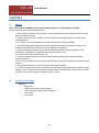
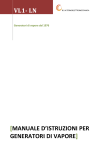
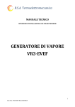
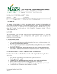
VL1- LN
B.S.A.TERMOELETTROMECCANICA
Generatori di vapore dal 1976
[USER MANUAL]
IMPORTANT WARNING
BEFORE INSTALLINF OR HANDLING THE APPLIANCE PLEASE CAREFULLY READ AN FOLLOW THE INSTRUCTION AND
SAFETY STANDARD DESCRIBED IN THIS MANUAL.
This generator produces pressurized steam by means a heat exchanger powered by a gas burner immersed in water.
The quality of water used affect the performance and life of equipment, the appliance may be supplied with untreated water, as long as
this is drinkable, demineralized or treated with a softener. The evaporated water is automatically replaced using a filling valve
GENERAL INSTRUCTIONS
This booklet constitutes an integral and essential part of the product and should be supplied to the installer. Read the instructions
contained in this booklet carefully as they give important directions regarding the safety of installation, use and maintenance. Preserve
this booklet with care for any further consultation.
The installation of the generator must be carried out in compliance with current regulations, according to the instructions of the
manufacturer and by qualified personnel. An incorrect installation can cause injury or damage to persons, animals and objects, for which
the manufacturer cannot be held responsible.
This appliance should only be used for the purpose it has been designed for. Any other use is to be considered improper and therefore
dangerous. The manufacturer cannot be considered responsible for any damages caused by improper, erroneous or unreasonable use.
Before carrying out any cleaning or maintenance operation, disconnect the appliance from the power supply, by using the main system
switch or through the appropriate interception devices.
In case of failure and/or malfunctioning, switch off the equipment and refrain from trying any repair or direct intervention. Call in qualified
personnel only. Any repair must be carried out by a servicing centre authorized by the manufacturing firm, one using original
replacements exclusively. Non-observance of the above could compromise the safety of the appliance. In order to guarantee the
efficiency of the appliance and its proper operation it is indispensable to keep to the manufacturer’s directions, by ensuring the periodical
servicing of the appliance is carried out by professionally qualified personnel.
As soon as one decides not to use the appliance further, one should take care to render innocuous those parts liable to be potential
sources of danger.
The transformation from a gas (natural gas or liquid gas) to a gas of another group must be made exclusively by qualified personnel.
Before starting up the generator for the first time ask qualified personnel to check:
a) that the data on the information plate corresponds to that required by the gas, and electrical supply networks;
b) that the calibration of the burner is compatible with the boiler output;
After each reopening of the gas cock wait a few minutes before restarting the generator.
Before carrying out whatever intervention which foresees the dismantling of the generator or the opening of any of the accesses for
inspection, disconnect the electrical current and close off the gas cocks.
Do not deposit containers of inflammable substances in the location where the generator is situated.
On noticing the smell of gas do not touch any electrical switch. Open all doors and windows. Shut off the gas cocks. Call qualified
personnel.
Never cover up the generator room’s air vents, the burner’s fan’s air-intake openings or any existing air ducts or air gratings, thus
avoiding:
- the formation of poisonous/explosive mixtures of gases in the burner room;
- combustion with insufficient air, which would be dangerous, costly and cause pollution.
The burner must at all times be protected from rain, snow and freezing.
The room where the generator is housed should be kept clean at all times, and there should be no volatile substances in the vicinity,
substances which could be sucked into the fan and could block up the internal ducts of the burner.
The burner must be connected to an effective system earthed in accordance with the current regulations. Should there be any doubts, the
verification should be made by qualified persons.
Never exchange neutral and phase wires.
The burner can be connected up to the mains supply using a plug connection only if the latter is of the kind that does not allow neutral
and phase wires to be reversed. Install a main switch for the heating system on the control panel, as required by current regulations.
The entire electrical system, and in particular cable cross-sections, should conform to the maximum absorbed capacity indicated on the
appliance data plate and in this manual.
Should the generator’s mains cable be found faulty, it must only be replaced by qualified persons.
The electrical connections must be made exclusively by qualified experts and the relative regulations in force must be scrupulously
applied.
After removing the packaging materials, check the content integrity and make sure that no damages have occurred during transportation.
In case of doubt, do not use the burner and contact the supplier. The packaging material (wooden cages, cartons, plastic bags, foam,
clips, etc...) are potential sources of pollution and danger, if left lying around; they should be collected up and disposed of in the correct
way (in a suitable place).
SUMMARY
PREFACE............................................................................................................................................................ 5
CHAPTER 1 ......................................................................................................................................................... 6
1.1
Models..................................................................................................................................................... 6
1.2
Description of the components ................................................................................................................... 6
1.3
Receipt and storage .................................................................................................................................. 7
1.4
Positioning and dimension ......................................................................................................................... 7
1.5
Removal of the cover ................................................................................................................................ 8
1.6
Characteristics of the supply water ............................................................................................................. 9
1.7
The chimney ............................................................................................................................................ 9
1.8
Safety valve ........................................................................................................................................... 10
1.9
Condensate saver (ECOCONDENSE) ..................................................................................................... 11
1.10
Burner ................................................................................................................................................... 12
CHAPTER 2 ....................................................................................................................................................... 13
2.1
Laying of pipes ....................................................................................................................................... 13
2.2
Pipe connections .................................................................................................................................... 14
2.3
Maintenance .......................................................................................................................................... 15
2.4
Controls and burner maintenance............................................................................................................. 16
2.5
Cleaning water filter ................................................................................................................................ 17
2.6
Electrical wiring ...................................................................................................................................... 18
CAPITOLO 3 ...................................................................................................................................................... 19
3.1
First start- power off ................................................................................................................................ 19
CHAPTER 4 ....................................................................................................................................................... 20
4.1
Warnings ............................................................................................................................................... 20
4.2
Controls and safety device....................................................................................................................... 20
VL1- LN
[USER MANUAL]
Cod. documento: VL1 MI 01
PREFACE
We congratulate on your purchase of a steam generator BSA which represents the fruit of years of research and
experimentation aimed at energy saving, environmental protection and work safety.
The optimal use of the generator requires the installation of a water softener, which preserves the product from calcareous
incrustations and ensures a constant efficiency over time, preventing failures that would otherwise be subject.
This problem has its origin in characteristics of water used, the treatment it undergoes before being put on the generator and
controls, more or less accurate, which are made by users on water treatment.
The B.S.A. strong years of experience has committed not only to build a generator that was extremely cheap to own and which
would offer absolute guarantees in terms of respect for the environment, but is also concerned to protect the generator
from any disruptions that may accidentally or through neglect create operational problems.
NOTE: Before unpacking the product to ensure any damage in transit. The same must be done right out of the
packaging, and every problem found must be reported to the carrier and suddenly to our office.
5
VL1- LN
[USER MANUAL]
Cod. documento: VL1 MI 01
CHAPTER 1
DESCRIPTION OF PRODUCT
1.1 Models
The code that characterized the model of the generator is composed of 9 characters:
1
2
3
4
1.2
Family
Potentiality
Burner Type: LN- Low Nox
Material: I- Inox AISI 316 L; F- Carbon steel
Description of the components
1
2
3
4
5
6
7
8
9
10
11
12
Gas interception valve
Water interception valve
Work and safety pressure switch
Level sensor
Steam line
Smoke-saver **
Condensate pump**
Premix burner
Drain valve*
Water pump
Check valve
Control panel
* Manual or automatic on demand
**Optional
6
VL1- LN
[USER MANUAL]
Cod. documento: VL1 MI 01
1.3 Receipt and storage
On receipt of the appliance verify the integrity and notify the carrier immediately any damage that may be derived from a transport
inadequate.
1.4 Positioning and dimension
For installation choose the most suitable position for the steam distribution, that is the position that minimises the length of the steam
outlet pipe.
The unit has been designed for wall installation or on a floor that must be able to support the weigth of the unit in normal operating
condition.
Figura 1
The metal casing of the generator heats up during operation, and the top may reach temperatures of over 50°C; check that this does not
cause any problem.
Mod. A
C
15*
350 450
40
500 550
70
600 650
90
650 700
140
750 800
200
750 900
*Versione murale
7
B
950
1200
1400
1700
1800
2000
A: depth
B: width
C: height
All dimensions are in mm
VL1- LN
[USER MANUAL]
Cod. documento: VL1 MI 01
1.5 Removal of the cover
To remove the casing of the generator, proceed as follows:
12-
Remove the screws ,
For the wall version Spread the wings of the hood
and remove paying attention to the cables.
8
VL1- LN
[USER MANUAL]
Cod. documento: VL1 MI 01
1.6 Characteristics of the supply water
The water used to supply the generator can be drinking water, demineralized or softened.
For correct operation of the generator, we recommend the use of softened water to ensure a longer life than the use of normal tap water.
1.7 The chimney
Our generators are pressurized, which means that the exhaust gases leaving the flue under the pressure of the pressure created by the burner,
but the installation of the chimney must be performed in a workmanlike manner.
The chimney must be constructed following the instructions:
Section must always be greater than or equal to the output of the generator
-
-
It must follow the shortest route avoiding corners and elbows at right angles.
Avoid long horizontal paths (you must always give the pipe a slope)
Engaging in an existing fireplace must be done through an appropriate invite so as not to interfering with the exhaust of the other
boilers, and the section of the main pipe should be sized so as to be able to dispose of the sum of the
flows of gas appliances connected to it.
Fig. 2
Installation mural
Inside the room
with outside air suction
(Device type C)
Fig. 1
Installation mural
Internal air suction from
the local.
(Device type B)
Fig. 3
Installation
mural outside
the local
9
VL1- LN
[USER MANUAL]
Cod. documento: VL1 MI 01
1.9
Condensate saver (ECOCONDENSE)
Optional equipment
The ECOCONDENSE is an appliance designed to enable to users considerable energy recovery, having the ability to absorb the
heat of condensate.
This energy in the absence of our unit, would be lost into the atmosphere as vapor, while in the presence of Ecocondense that
heat is absorbed from the water supply that is fed into the generator, thus lowering the fuel consumption for steam production .
The water inlet temperatures are significantly lowered, while preserving the pump failure due to thermal shock.
The recovered heat is reused by our steam generator, allowing the customer to amortize the cost of the economizer in a short
period of time.
The% recovery is described in the following table:
example:
- Temperature of steam at 5 bar:
- water energy (condensate):
- Steam energy:
151,1°C
151 Kcal
657.3 Kcal
From the Mollier table we can deduce that the heat of water (condensate at 151.1 ° C) corresponds to over 23% of the total
heat used for steam production. Calculating the physiological loss of 10%, is that where you are working with many of
condensate return is 13% saving of fuel.
EXAMPLE OF INSTALLATION WITH CONDENSATE SAVER.
11
VL1- LN
[USER MANUAL]
Cod. documento: VL1 MI 01
1.10 Burner
On our generators are installed commercial premix burners, to ensure an efficient service network.
Marca:
Modello:
Tipo gas: Metano; GPL
Potentiality:
For details, see the instruction manual attached burner.
Gruppo rampa gas
1.
2.
3.
4.
5.
6.
7.
Gas pressure down line test point (P2)
Gas pressure down line test point (P1)
Gas supply
Flange
Gas valve
Minimum gas flow adjustment on the stabiliser (V2)
Maximum gas flow adjustment (V1)
8. Air/gas mixer in the suction line circuit
Burner adjustment
The optimum adjustment of the burner requires an analysis of flue gases at
the boiler outlet.
The burner application at the generator, the adjustment and the testing
must be carried out in compliance with the Instruction manual of the
generator itself, including the control of the CO and CO2 concentration in
the flue gases and of their temperature.
Check in sequence:
• Maximum output
• Minimum output
• Ignition output
Minimum output
Minimum output should match the value required by the boiler
that is used. To increase or decrease its value, adjust the trimmer
MIN located on the control box.
Measure the gas delivery on the counter to precisely establish the
burnt output.
Using a smoke analyser, measure the value of the CO2 or the O2
in order to optimise the burner calibration.
The correct values are: CO2 8.5÷9% or O2 5÷5.5%.
To correct these values act on the gas valve in the following way:
– to increase the gas delivery and the CO2: turn the screw V2
clockwise (tighten).
– to reduce the gas delivery and the CO2: turn the screw V2
anticlockwise (unscrew).
Maximum output
Maximum output should match the value required by the boiler
that is used.
To increase or decrease its value, adjust the trimmer MAX located
on the control box.
Measure the gas delivery on the counter to precisely establish the
burnt output.
Using a smoke analyzer, measure the value of the CO2 or the O2
in order to optimize the burner calibration.
The correct values are: CO2 8.5 ÷ 9% or O2 5÷5.5%.
To correct these values act on the gas valve in the following way:
- to increase the gas delivery and the CO2: turn the screw V1
anticlockwise (unscrew).
- to reduce the gas delivery and the CO2: turn the screw V1
clockwise (tighten).
Ignition output
The ignition output can be varied by actin
12
VL1- LN
[USER MANUAL]
Cod. documento: VL1 MI 01
CHAPTER 2
INSTALLAZIONE E POSA IN OPERA
2.1
Laying of pipes
In order to better realize the potential of our products, the steam line must be done following certain rules on, in order to avoid the
dragging of water, which could influence the work of users.
The rules are few and simple to follow:
- The steam pipe lowered machines must always be taken over
the main pipe (umbrella-handles). Fig.1.
- The steam pipes must have a slope towards the use of
10%, while 10%of the condensate piping to the generator. Fig. 2
- At the end of the line is a good idea to apply a steam trap that
removes the water formed by condensation of steam.
- The narrowing of the tube should be done gradually. Fig 3.
- Avoid using elbows, but always curved. Fig 4.
- If you need to create horizontal lines above 10 meters, you must
mount expansion joints.
Please note that proper execution of the distribution line to
the steam generator uses is essential condition for the proper
functioning of a system.
fig. 1
fig. 2
fig. 3
fig. 4
13
VL1- LN
[USER MANUAL]
Cod. documento: VL1 MI 01
2.2
Pipe connections
The installation of the generator requires connection to water
supply, gas supply and electricity.
- The connection of the feed water can also be
performed using a flexible tube with a diameter equal to
that of the solenoid load, as shown in Figure 1 is important to
provide for the installation of a water filter and a first check
valve to connect to the generator.
- The burner should be operated with the type of fuel for
which was prepared as indicated on the rating plate and in
the typical specifications provided in this
manual. The fuel line that feeds the burner must be
perfectly sealed, made of a rigid, with the interposition of
a metal expansion joint with flange or threaded. It must
also be equipped with all mechanisms of control and
security required by local regulations. Pay
particular attention to the fact that no external matter entering
the line during installation.
- The connection to the outlet of the steam is necessary to
provide for the installation of a valve suitable for use for the
construction of the steam lines refer to the instructions
in Section 2.1.
Figura 2
Figura 1
Figura 1
14
VL1- LN
[USER MANUAL]
Cod. documento: VL1 MI 01
2.3
Maintenance
The periodic maintenance is essential for the good operation, safety, yield and duration of the generator.
It allows you to reduce consumption and polluting emissions and to keep the product in a reliable state over time.
The maintenance interventions and the calibration of the generator must only be carried out by
qualified, authorised personnel, in accordance with the contents of this manual and in compliance with
the standards and regulations of current laws.
Before carrying out any maintenance, cleaning or checking operations::
- Disconnect the electricity supply from the generator by means of the main switch of the
system;
- Close the fuel interception tap;
- Close the water interception tap;
The generator is a combination in which to get the maximum, you must check the proper functioning of each element:
1- The burner
2- Water filters
Note: For safety accessories is obligatory to carry annual operating verifications, these devices are:
-
SAFEETY VALVE
SAFETY PRESURE
SAFETY THERMOSTAT
These checks must be performed by authorized technicians, who at the end of the tests must issue a
certificate attesting the execution of the same and the actual condition of the components.
15
VL1- LN
[USER MANUAL]
Cod. documento: VL1 MI 01
2.4
Controls and burner maintenance
Maintenance frequency
The combustion system should be checked at least once a year by a representative of the manufactured or another specialised
technician.
Checking and cleaning
Flexible hoses
Check there are no occlusion or obstructions in the fuel supply pipes, in the air suction areas and in the combustion product waste
pipe.
Gas leaks
Make sure there are no gas leaks in the following areas:
- On the meter-burner pipework
- On the mixer/valve connection
- On the burner fastening flange where gasket are fitted
Combustion head
Inspect the combustion head and make sure the fabric is undamaged and does not feature large or deep holes or corroded areas.
Also make sure that no parts have warped as a results of the high temperature
Electrodes assembly
Make sure neither the electrodes nor probe show marked warping or oxidation on surface.
Make sure distances are still in line with those indicates in the burner manual.
Gas train
Check valve setting and proportionality of operation by analyzing flue gases
Combustion
Let the burner run at full capacity for about ten minutes, setting all the elements correctly as explained in burner manual.
Then carry out the analysis of the combustion by checking:
-
CO2 percentage (%);
CO content (ppm);
NOx content (ppm);
Ionisation current (µA);
Flue gas temperature at the flue.
Adjust the burner if the combustion values found at the beginning of the operation do not comply with the regulations in force or, at
any rate, do not produce good combustion.
Use the appropriate card to record the new combustion values; they will be useful for subsequent control.
16
VL1- LN
[USER MANUAL]
Cod. documento: VL1 MI 01
2.5
Cleaning water filter
The water filter is very important for proper operation and the duration of the generator, in fact holding impurities from the water
lines preserve the integrity of the solenoid load generator to avoid malfunctions.
Periodically the filter must be cleaned otherwise the generator in bulk due to lack of water to clogging of the filter.
To clean the filters is sufficient, once open, intensively washed with clean water.
17
VL1- LN
[USER MANUAL]
Cod. documento: VL1 MI 01
2.6
Electrical wiring
For electrical connections, bring 200 V + T. while the connections to the burner is important to follow the wiring diagram provided by
the BSA.
The B.S.A. disclaims any liability for links to be made for them by whom, or burners.
FOR DETAILS SEE ANNEX THE WIRING.
2.7
Pressure command
To modify the pressure of work or modulation you must work on the pressure switch.
18
VL1- LN
[USER MANUAL]
Cod. documento: VL1 MI 01
CAPITOLO 3
MANGEMENT GENERATOR AND COMPONENTS
3.1
First start- power off
FIRST START
IMPORTANT: All connections must be carried out indicated in a workmanlike manner, in strict accordance with sections dates, plus
any increase, but never reducing them, not to destabilize the system.
Make sure that the voltage corresponds to the data generator.
1.
2.
3.
4.
5.
Calibrate the instruments of regulation in relation to the desired steam pressure, never change the calibration of safety.
Proceed in the purge gas pipelines that supply the burner
Open the valve by hand fuel and water supply.
Turn on the switch. Turn the dial on the control panel in position 1, the generator will automatically load to the water before
turning on the burner.
The burner is pre-calibrated during testing at the manufacturer, in any case it is recommended to run a combustion control.
NOTE: It 'possible that the fuel in the pipelines there is still formation of air bubbles that can cause the burner failure. After
a few minutes, or the achievement of the working pressure, check the tightness of all piping and connections and eliminate
any loss that may have formed during transport.
Upon reaching the maximum pressure set by the user stops the generator until the lower reaches of the same values
arranged in the pressure switch which will restart the generator producing steam.
With this operation, the generator is ready for use.
POWER OFF
Finished using the generator off the switch that removes power to the control panel.
It 'a good idea to also close the water valve that feeds the generator to avoid them during the night, fill the generator.
For fuel, in the case of gas, the law provides that the valve is always closed at the end of each working day.
To automate this task you can use a solenoid valve on the gas pipeline is located outside the room where the generator.
19
VL1- LN
[USER MANUAL]
Cod. documento: VL1 MI 01
CHAPTER 4
4.1
Warnings
N.B. : Failure to follow WARNING causes the immediate revocation of responsibility by the BSA.
Check the hydraulic lines, electrical and gas (first on)
1. Every 2 years to ensure the smooth operation of work equipment and security personnel to BSA, which will
issue the certificate of review.
2. For each repair technicians to call BSA, for each unauthorized repair BSA disclaims any liability and will
void the guarantee
3. Do not weld or mount any equipment not related to the generator or unauthorized BSA
4. Any tampering with safety systems and work of the generator will cause the automatic revocation of the
guarantee and the BSA will no longer have any responsibility of the generator.
5. Check the settings of the burner, while making an authorized technician. Improper adjustment of the
burner due to a malfunction of the generator and a high consumption of fuel.
6. Periodically clean water filters (see chap. 2.6).
7. Each time a repair is carried out to check the proper operation of the generator and all of the safety
equipment and work.
8. Do not carry out maintenance or opening connections without turning off the generator and reset the internal
pressure.
9. The repair and maintenance of the burner must be performed by qualified.
10. The B.S.A. not be held responsible if the safety valve, fulfilling its function (downloading the steam), causes
damage or injury. The BSA recommends that the exhaust steam of the safety valve is performed so as to drain
the steam in an area where there is no danger to people or things.
4.2
Controls and safety device
1. GENERAL
o Safety valve
o Safety pressure switch (steam pressure)
o Safety temperature switch (steam temperature)
o Level probes
o Level switch
o
20