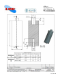
1
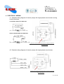
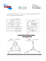
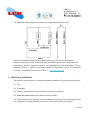
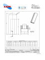
LGB s.r.l.
Via Romania, N° 7
35127 PADOVA Z.I.
++39 049 6989310
++39 049 6989313
Rev. 00 del 04/10/2013
USER'S AND MAINTENANCE MANUAL OF LGB PRODUCTS
LGB s.r.l. thanks you for purchasing its products.
For a safe, effective, efficient and correct use of your LGB product, please read this manual
carefully.
This User's Manual is subject to copyright and its content may be subject to changes without
prior notice.
This User’s manual and the product have been prepared and tested according to appropriate
procedures, should misprints or other types occur please inform our
business contacts (www.lgb-pumps.it).
LGB s.r.l. assumes no responsibility for improper use of the product, nor for any direct or
indirect damages (please read carefully this manual prior to use and take note of all warnings
contained in it).
The electric motor pumps of LGB s.r.l. cannot be used for alimentary and drinking water
use, except for special customizations requested by the customer and in compliance
with the Decree Ministerial n ° 34 dated 21/03/1973 (eg. pumps used in ice makers, etc.)
Pag. 1 a 14
LGB s.r.l.
Via Romania, N° 7
35127 PADOVA Z.I.
++39 049 6989310
++39 049 6989313
CONTENTS:
- 1. General description of products;
- 2. Identification labels;
- 3. Installation;
- 4. Electrical connection scheme;
- 5. Additional Warnings;
- 6. Inspection and maintenance;
- 7. Replacement of Front pump casing;
- 8. Replacement of Impeller;
- 9. Replacement of Mechanical seal;
- 10. Faults and Remedies;
- 11. Declaration of Conformity;
- 12. Technical Specifications;
- 13. Product Warranty.
Pag. 2 a 14
LGB s.r.l.
Via Romania, N° 7
35127 PADOVA Z.I.
++39 049 6989310
++39 049 6989313
1. GENERAL DESCRIPTION OF PRODUCTS
This is to certify that the system of quality management of LGB s.r.l. conforms to the ISO
9001:2008 certification for all fields of activities undertaken, such as design and development
of electric motor pumps for industrial dishwashers, sanitary facilities and swimming pools,
electric motor pumps used in the medical industry, electric motors for industrial ovens and
coffee machines.
2. IDENTIFICATION LABELS
Nameplate for Electric motor pumps:
Compliance with the Regulations 2002/95/EC
Winding equipped with thermal protector - Date of manufacture
EL.POMPA = Product Description; V. = Power supply voltage; A.= Total absorbed current; H
min. = Minimum head; Cond µF = capacity of the capacitor; Isol.Cl. = Isolation class; C.F. =
Supplier Code; ….. /min = rpm; C.C. = Customer Code; Hz. = Rated frequency; kW. =
Maximum power consumption (P1); H max. = Maximum head; TF = Maximum temperature of
the pumped fluid; IP = Protection grade.
Pag. 3 a 14
LGB s.r.l.
Via Romania, N° 7
35127 PADOVA Z.I.
++39 049 6989310
++39 049 6989313
Nameplate for Motors:
Compliance with the Regulations 2002/95/EC
Winding equipped with Thermal protector -
Date of manufacture
Motore asincrono = Product Description; V. = Power supply voltage: A. = Total absorbed
current; IP = Protection grade; µF = capacity of the capacitor; kW P1 = Rated input power;
Iso. Cl. = Isolation Class; C.F. = Supplier Code; kW P2 = Rated power at shaft; ….. /min =
rpm; C.C. = Customer Code; Hz = Rated frequency.
In addition:
In addition to the nameplate, on each pump / motor is applied a second adhesive label
bearing the serial number, consisting of production lot (a), the date of production (b) and
the ID number of the product (c).
The serial number (repeated with barcode) allows to trace at any time the report
testing performed at the end of the production line, carried out on 100% of the components
produced.
Pag. 4 a 14
LGB s.r.l.
Via Romania, N° 7
35127 PADOVA Z.I.
++39 049 6989310
++39 049 6989313
3. INSTALLATION
3.1. Always check manually the free rotation of the shaft assembly acting on the rear
part of the same where it is always present the impression dedicated to act with just a
screwdriver;
3.2. Fix the product on a solid base dedicated to ensuring a rigid and vibration free
position, as well as an access for visual inspection;
3.3. Fix correctly the piping to the suction inlet and the discharge outlet of the hydraulic
body, making sure that the pipes do not have a lesser diameter;
3.4. All the pipes used for the various hydraulic connections must be perfectly sealed;
3.5. All the piping connected to the pump must be firmly supported , the lack of support
may lead to the breakage of the pump casing;
3.6. Connect electrically the product by matching the nameplate data
of the product with the power supply voltage that must be the same for voltage and
frequency;
3.7. Before starting up the product , check that the pump casing is full of liquid;
3.8. Check that the direction of rotation of the shaft assembly is correct (in three-phase
motors it is indicated by the arrow printed on the adhesive label affixed to the product);
3.9. ONLY FOR THREE-PHASE ELECTRIC MOTORS AND MOTOR PUMPS: after
each new connection, the lack of phase or voltage , it is possible that the phases get
reversed, therefore you have to check the correct direction of rotation. The wrong
direction of rotation causes overheating of the motor, likely vibrations, reduces
significantly the performance of the electric motor pump and causes probable damage
to the pump casing (in the case where the impeller unscrews itself);
3.10 It is not intended the use of the product for fluids other than those of normal use
(please abide to the amount of dissolved detergents and rinse aids recommended by
the manufacturer of the machine where it is inserted, do not use solutions therefore not
indicated with excessive percentage of chlorides and / or Chlorites, except for
specific applications requested to LGB s.r.l.
Pag. 5 a 14
LGB s.r.l.
Via Romania, N° 7
35127 PADOVA Z.I.
++39 049 6989310
++39 049 6989313
4. ELECTRICAL WIRING:
4.1. Standard wiring diagram of electric pumps with single-phase wound stator running
in both directions;
CLOCKWISE DIRECTION WIRE SIDE
ANITCLOCKWISE DIRECTION WIRE SIDE
Example of connection in the terminal box of i totally enclosed and
fan cooled motors
4.2. Standard wiring diagram of electric pumps with single-phase wound stator;
Example of connection in the terminal box of totally enclosed and
fan cooled motors
Pag. 6 a 14
LGB s.r.l.
Via Romania, N° 7
35127 PADOVA Z.I.
++39 049 6989310
++39 049 6989313
4.3. Standard wiring diagram of electric pumps and motors with three-phase wound
stator with independent thermal protector;
Example of connection in the terminal box of totally enclosed and
fan cooled motors (400V connection)
Pag. 7 a 14
LGB s.r.l.
Via Romania, N° 7
35127 PADOVA Z.I.
++39 049 6989310
++39 049 6989313
4.4. Standard wiring diagram of motors with single-phase wound stator;
Due to the numerous requests for customization, you can find on the market
electric pumps and motors with wiring diagrams different from those standard ones
listed above, both for the position and for the colouring of the electrical cables. This is
caused by LGB s.r.l. need to unify their products. In any cases of doubt, it is advisable
to contact a qualified Technician at LGB s.r.l. (www.lgb-pumps.it).
5. ADDITIONAL WARNINGS
The product can be stored in a warehouse under conditions of an environment that is:
5.1. Dry;
5.2. Ventilated;
5.3. Clean (if necessary cover the product or place it in a carton);
5.4. Keep the product away from direct sources of heat;
5.5. During the period of storage, so not to cause the blocking of the mechanical seals,
it is necessary to act periodically on the rear of the motor shaft, by rotating it.
Pag. 8 a 14
LGB s.r.l.
Via Romania, N° 7
35127 PADOVA Z.I.
++39 049 6989310
++39 049 6989313
6 . INSPECTION AND MAINTENANCE
6.1. Check that the power supply is switched off and that the product cannot restart,
even accidentally, before you start working on it;
6.2. Difficult working conditions or occasional uses of the product makes it necessary
frequent inspections. To ensure through time the safety, reliability and performance,
the product must be subject to maintenance work consisting of actions of verification,
control and substitution;
6.3. The inspections are essentially visual, verifying that the components of the
product externally and internally have not been dented, corroded and in any case
affected in degradation phenomena, and paying particular attention to components
made out of plastic material, especially for dents, cracks and breakages. Obviously,
the presence of such phenomena must involve the replacement of damaged parts;
6.4. Components subject to wear and tear (e.g. mechanical seals) must be checked
periodically;
6.5. MECHANICAL SEAL, it is advisable a use of maximum of 8000 hours, during
which it is appropriate to carry out the following measures:
6.5.1. In the system where the product is installed, appropriate filters must be used,
necessary to block solids and/or abrasive parts that can position themselves
between the sliding surfaces causing damage and consequently causing loss of
pressure.
6.5.2. Make sure that the sliding surfaces are constantly lubricated by the pumped
liquid, maintaining the proper water level inside the dishwasher tank and ensuring
that during normal use an excessive
amount of foam does not form. In the case of partial or missing lubrication, the
sliding surfaces of the mechanical seal will overheat and the heat (not removed by
the pumped liquid) is transmitted in its entirety, causing a sudden deterioration of
the sliding surfaces;
6.6. BEARINGS, it is not indicated a time limit of use, but nevertheless the following
steps need to be taken:
6.6.1. Make sure that dust and / or metal chips or other kind do not settle on the
motor shields;
Pag. 9 a 14
LGB s.r.l.
Via Romania, N° 7
35127 PADOVA Z.I.
++39 049 6989310
++39 049 6989313
6.6.2. Make sure that in the area of shaft bearings no leaks of grease are present,
this might be a symptom of excessive temperature attained.
6.7. In the case where the user is not able to perform the ordinary or the
extraordinary maintenance, these operations must be carried out by the qualified staff
at LGB s.r.l.
6.8. Any type of intervention on the product by unauthorized persons, renders
automatically void the performance warranty by LGB.
7. REPLACEMENT OF PUMP CASING
7.1. Unscrew the screws / nuts coupling the pump casing’s front to the flange;
7.2. Assemble the new pump casing’s front, making sure that there are no deposits of
dirt on the sealing surfaces of coupling in correspondence with the O-ring;
7.3. At every maintenance operation and control where the pump front casing needs to
be removed, it is necessary to replace the O-ring.
8. REPLACEMENT OF IMPELLER (The following operations can be performed only by
qualified persons).
8.1. Unscrew the screws / nuts coupling the pump casing’s front to the flange (as
above);
8.2. In the case of the presence of a nut that locks the impeller, unscrew the nut and
then unscrew the impeller;
8.3. In the case that the nut is not present and does not lock the impeller, simply
unscrew the impeller;
8.4. To unscrew the impeller you must keep locked the shaft assembly by acting in the
rear part of the electric pump, taking great care not to damage nor the copper crowns
of the wound stator, nor the cooling flaps of the rotor (in the case of electric pumps with
in-built motors, slip off the fan cover and the fan, keeping locked the rear of the motor
shaft);
8.5. Proceed with the replacement of the impeller and reassemble the pump casing’s
front as indicated in point n° 8.2.
Pag. 10 a 14
LGB s.r.l.
Via Romania, N° 7
35127 PADOVA Z.I.
++39 049 6989310
++39 049 6989313
9. REPLACEMENT OF MECHANICAL SEAL (The following operations can be performed
only by qualified persons).
9.1. Mechanical seals are precision components and as such they require a proper and
accurate assembly.
9.2. Do not wet the sliding surfaces and the rubber seals of EPDM type with
lubricants.
9.3. The seal surfaces, at the time of assembly, must be clean and dry.
9.4. Avoid totally the use of excessive force during insertion.
9.5. Avoid totally that the mechanical seal is subject to shocks or impacts during the
assembly.
9.6. Follow the steps indicated in the instructions for the replacing of the impeller and
the pump front casing (points n°8 and 9);
9.7. IN THE CASE OF ROTATING SEAL ON SHAFT: slip off the seal to replace,
insert the new seal on the motor shaft taking extreme care pushing it in place by
tightening the impeller;
9.8. IN THE CASE OF ROTATING SEAL ON THE SPIGOT OF IMPELLER: slip off
the seal to replace, place the new seal in the dedicated buffer (DIS0136), moisten the
spigot of the impeller with denatured ethyl alcohol and insert the seal until it rests on
the bottom plate of the impeller;
9.9. Slip off the fixed seal inserted into the flange with the help of a flat screwdriver,
moisten the seal housing (present in the flange) with denatured ethyl alcohol and
proceed with the insertion of the fixed seal until its complete settling in place with the
appropriate dedicated buffer (DIS0137).
Pag. 11 a 14
LGB s.r.l.
Via Romania, N° 7
35127 PADOVA Z.I.
++39 049 6989310
++39 049 6989313
Pag. 12 a 14
LGB s.r.l.
Via Romania, N° 7
35127 PADOVA Z.I.
++39 049 6989310
++39 049 6989313
Pag. 13 a 14
LGB s.r.l.
Via Romania, N° 7
35127 PADOVA Z.I.
++39 049 6989310
++39 049 6989313
10. FAULTS AND REMEDIES
IN ALL CASES OF DOUBT PLEASE ALWAYS CONTACT A QUALIFIED TECHNICIAN AT
LGB s.r.l. (www.lgb-pumps.it). All products supplied by LGB are subjected to inspection tests,
for both the electric and hydraulic parts, in respect of any cases of doubt, the Customer may
request the LGB test report by providing the complete serial number present on the
nameplate Quality Check that is applied to the product after passing all the tests successfully.
11. DECLARATION OF CONFORMITY
All products supplied by LGB s.r.l. comply with the standards, requirements,
Declarations and Certifications specified in the section QUALITY in our company website
(www.lgb-pumps.it).
12. TECHNICAL SPECIFICATIONS
In the LGB s.r.l. website (www.lgb-pumps.it) there is present the section
"CATALOGUE", where by product type are indicated the technical characteristics and
the overall dimensions of our standard products.
The catalogue is purely indicative, since for each model of electric pump /motor
already exists various solutions of customization. For proper consultation and any
requests we suggest you contact the Sales Department of LGB s.r.l.
13. PRODUCT WARRANTY
For product warranty please refer to the General Conditions of Sale in the LGB s.r.l. website
(www.lgb-pumps.it).
Pag. 14 a 14