1
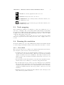
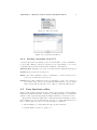
Octopus Emulation System
User’s Manual
Fabio D’Aprano
Massimiliano de Leoni
Universit`a di Roma “La Sapienza”
Dipartimento di Informatica e Sistemistica - DIS
March 18, 2007
Contents
1 Installation and Setup
1.1 Disclaimer about third party software . . . . . . . . . . . . . . .
1.2 Server Side Setup . . . . . . . . . . . . . . . . . . . . . . . . . . .
1.3 Client Side Setup . . . . . . . . . . . . . . . . . . . . . . . . . . .
2
2
2
3
2 Setting and running the emulation
2.1 Scenario setup . . . . . . . . . . . .
2.2 Scenario design . . . . . . . . . . . .
2.3 Node mapping . . . . . . . . . . . .
2.4 Running the emulation . . . . . . . .
2.4.1 View Menu . . . . . . . . . .
2.4.2 Sending commands from GUI
2.5 Loss functions editor . . . . . . . . .
4
4
5
7
7
7
8
8
.
.
.
.
.
.
.
.
.
.
.
.
.
.
.
.
.
.
.
.
.
.
.
.
.
.
.
.
.
.
.
.
.
.
.
.
.
.
.
.
.
.
.
.
.
.
.
.
.
.
.
.
.
.
.
.
.
.
.
.
.
.
.
.
.
.
.
.
.
.
.
.
.
.
.
.
.
.
.
.
.
.
.
.
.
.
.
.
.
.
.
.
.
.
.
.
.
.
.
.
.
.
.
.
.
.
.
.
.
.
.
.
A Server Protocol
10
B Windows Mobile peers setup
B.1 Windows Mobile Setup . . . . . . . . . . . . . . . .
B.1.1 Installing required software . . . . . . . . .
B.1.2 Devices setup . . . . . . . . . . . . . . . . .
B.2 Using Microsoft Device Emulator . . . . . . . . . .
B.2.1 Microsoft Device Emulator Setup . . . . . .
B.2.2 Running more than one instance on a single
1
. . . . .
. . . . .
. . . . .
. . . . .
. . . . .
machine
.
.
.
.
.
.
.
.
.
.
.
.
.
.
.
.
.
.
12
12
12
12
13
13
15
Chapter 1
Installation and Setup
Before you proceed with software installation, a traditional Local Area Network
must be set up between the machine that will act as server and every peer you
will want to place in the emulated environment. In the initial situation, each
machine must reach each other in the LAN being in the same sub-network. In
this document we will assume that all the machines are configured under the
192.168.0.x, netmask 255.255.255.0 network.
1.1
Disclaimer about third party software
To run certain emulation scenarios, such as those that include hand held devices,
you will need to install third party software. This software is subject to change
over time and under the responsibility of their original development teams.
This manual will provide a generic description of the procedures you have to
do in order to configure and make these particular configurations work with the
octopus platform. If you encounter any problem or difficulty not mentioned in
this document using third party software, please refer to their updated official
documentation.
1.2
Server Side Setup
The first step is to choose a personal computer in the LAN that will act as server.
We will proceed with the emulation software installation on this machine as
described below. Please note that you have to install on server the latest version
of Java Runtime Environment available for download on http://java.sun.com
and the TCP/IP 8888 port must be available for use.
Windows Systems This software uses the third party library WinPcap [1]
which java JPcap [2] library is based to provide a low level layer that captures
and delivers network packets. In order to run the emulation software you will
need to download and install this library and then launch the run.bat file
provided in the installation package.
The next thing to do is to assign a static IP address to server. We will
assume we will use 192.168.0.1 IP address.
2
CHAPTER 1. INSTALLATION AND SETUP
3
Linux/Unix Systems Linux/Unix version is still under development and
testing.
1.3
Client Side Setup
Since the emulation server acts as a router you will need to set the next routing
hop manually on each peer; next hop will be of course the emulation server.
To get the setup easier, we can work with address intervals: a suggestion
is to assign to peers addresses greater than 192.168.0.128. In this way, using
the routing rules showed below, each peer can establish a direct connection to
server while the communication between peers passes through server.
Windows Systems First we assign to each machine a static IP address
greater than 192.168.0.128 (i.e. 192.168.0.129, 192.168.0.130, ... ) then
we launch a command shell and type:
route ADD 192.168.0.128 MASK 255.255.255.128 192.168.0.1
This procedure has to be made on all the peers in the network except for
the server.
Windows Mobile/CE Systems The emulation platform has the support
also for hand-held devices if they have a network interface and are able to
manage routing tables like Windows or Linux systems. A third party software
that allows the routing tables management is the free nettools utility part of
the Pocket Console [3] package. You will have to install in this sequence Pocket
Console driver, CMD utility and Nettools utilities.
Finally we assign to each hand-held device a static IP address greater than
192.168.0.128 (i.e. 192.168.0.129, 192.168.0.130, ... ) then as in Windows
systems we launch the command shell and type:
route ADD 192.168.0.128 MASK 255.255.255.128 192.168.0.1
This procedure has to be made on all hand-held peers in network except for
the server. A more detailed procedure will be described in Appendix B.
Linux/Unix Systems First we will assign to each machine a static IP address greater than 192.168.0.128 (i.e. 192.168.0.129, 192.168.0.130, ... )
then we launch a command shell and type:
route add 192.168.0.128 netmask 255.255.255.128 gw 192.168.0.1
This procedure has to be made on all the peers in the network except for
the server.
Chapter 2
Setting and running the
emulation
This chapter describes how to design and run an emulation scenario.
2.1
Scenario setup
At octopus’ startup will appear a dialog window asking you some basic information in order to run the emulation as showed in Figure 2.1.
All the options are described below:
Select MANET packet delivery mode: This section allows you to choose
the packet routing mode that octopus will use when emulation has started.
The first one is Single-hop delivery, this means that packets will be delivered if
destination is a source’s direct neighbor only. This mode is the more realistic
and is useful to test device implemented wireless routing protocols since real
physical layer allows only direct neighboor packet deliveries. The second one
is Multi-hop delivery (OCTOPUS routing). Selecting this option, allows you
to have an emulator implemented routing policy where routing path is always
assumed as the shortest path from the packet source node to destination node.
Select Node mobility Model: octopus allows you to choose between two
mobility models: Waypoint and Voronoi.
Waypoint is the simplest and does not consider obstacle presence. Nodes
move toward the specified point following a single line. Selecting this option
after some obstacles were previously added will cause them to hide.
Voronoi assumes obstacle presence. Selecting this model, nodes will move
avoiding obstacles and will follow precalculated paths according to obstacle
positions.
Field Size:
height.
You can specify here virtual environment physical width and
4
CHAPTER 2. SETTING AND RUNNING THE EMULATION
5
Figure 2.1: Configuration Window.
Rectangular Obstacles Detail: when Voronoi mobility model is selected,
you can modify the obstacle sampling rate in order to make a more detailed
Voronoi graph. Lower it is and more detail you will get in the resulting graph.
Warning: very low intervals may cause the software to run very slow.
Virtual Broadcast Address: this is the address that device implemented
custom protocols will have to use instead of IP protocol provided broadcast
address. Sending a packet to this address means that only node neighbors will
receive that packet.
Select network device which will be used as Gateway: Select here the
network card connected with other peers. Pay attention to this, because a wrong
card will not make the emulation work!
This window is recallable at any time by selecting Emulation->Options
menu. Please note in order to change network adapter you will have to restart
the application.
2.2
Scenario design
Scenario design is a graphical phase. You will have to create nodes and set their
position in the emulated environment, insert obstacles and named locations.
Figure 2.3 depicts the main software window that will be used as Scenario
Editor.
Toolbar GUI buttons
CHAPTER 2. SETTING AND RUNNING THE EMULATION
6
Figure 2.2: Main Window.
•
Add Node: This button allows you to create a new node. To add
a node click on this button and then choose a position in the work area.
Node position can be changed later via drag and drop or editing its properties on the left panel of GUI.
•
Add Location: This button allows you to add a location. A location
is used to label a place in the emulated environment (i.e. House, Church,
etc.). To add a location click on this button and then choose a position in
the work area. Location position can be changed later via drag and drop
or editing its properties on the left panel of GUI. Location properties panel
allows also to set a name to selected location.
•
Add Obstacle: This button allows you to draw a rectangular shaped
obstacle. To add an obstacle, click on the first point then click again to
set the second point of the rectangle.
•
Select Object: This button allows you to set the active object by
clicking on it. Once selected, you can edit object properties in the left
GUI panel. This button allows also you to move objects by drag and drop
them.
•
Delete Object: clicking on this button allows you to delete the
active selected object.
•
Zoom In: Zooms the graphical scenario area in.
CHAPTER 2. SETTING AND RUNNING THE EMULATION
•
Zoom Out: Zooms the graphical scenario area out.
•
Zoom Reset: Resets the view to Zoom 1:1.
7
•
Start Emulation: If not already started, this button allows you to
start the emulation process.
•
Stop Emulation: If not already stopped, this button allows you to
stop the emulation process.
2.3
Node mapping
Before running the emulation you will have to bind every emulated node to a
real device or machine. Two of the characteristics that identify a real machine
in a network are MAC address and IP address. octopus actually implements
an ARP resolver that automatically assigns MAC address to each node which
a valid IP address has been provided.
To proceed with this operation, just select a node and edit its IP address
inside the properties in the left GUI panel, then click on Apply button on
bottom.
2.4
Running the emulation
To run the emulation process, click on Emulation->Start menu. Ensure that all
nodes are mapped and named. This operation may take some time to execute.
2.4.1
View Menu
The view menu allows you to change some visual settings such as Show Range,
Show Neighbors, Show Voronoi Paths and Antialiasing.
• Activating Show Range, the graphical interface will show a colored circle
around each node in current scenario. This circle represents the maximum
distance in which nodes can communicate; this range is defined by the
higher bound of the loss function definition interval (See Section 2.5 for
more details).
• Show Neighbors menu entry will trace a blue line in the graphical scenario
that shows if a node is linked (i.e. is in radio range) with another.
• By selecting Show Voronoi Paths, if you are using the Voronoi Mobility
Model, all possible paths will be shown in the graphical environment representation as grey lines. Please note that paths will be shown only when
emulation is running and may cause the program to run slow on low end
machines.
• Enabling Antialiasing, graphical scenario will have a smoother aspect, but
may cause the program to run slow.
CHAPTER 2. SETTING AND RUNNING THE EMULATION
8
Figure 2.3: The View menu.
Figure 2.4: Loss functions window.
2.4.2
Sending commands from GUI
octopus allows the user sitting by the server machine to send commands to
nodes locally. This is possible by selecting a node and clicking on one of the
command buttons in the left GUI panel. Available commands are:
Random Dest Assigns to selected node a random picked destination and speed.
StopNode Stops selected moving node.
Follow Once this command is active you will have to click on another node.
Selected node will follow chosen node.
SetDest Once this command is active you will have to click on a position of
the scenario map. Selected node will start immediately to move towards
that position with specified speed according to current mobility model.
2.5
Loss functions editor
Figure 2.4 shows the loss functions editor dialog. It is possible to insert multiple
functions in different intervals of distance, all functions must be expressed in
variable r that represents the physical emulated distance between two nodes.
Every function inserted must have a valid interval that will make it active
if the distance is between that interval. In order to provide this interval, you
have to fill the first two text boxes, respecting these conditions:
1. Interval must not overlap with any other provided interval.
2. Bounds must be greater or equal to 0.
CHAPTER 2. SETTING AND RUNNING THE EMULATION
9
3. Lower bound has to be inserted on the left box and upper bound has to
be inserted on the right box.
Any other interval that does not satisfy these conditions will make your function
invalid and it will not be added in the function list.
Once a valid interval is provided, you will have to insert the function by
filling the large text box below, then click Add button. If interval and function
are well formed, a new item will appear in the list box below, otherwise you will
get an error message.
At octopus startup you will find a default function:
0 <= r < 100: F(r) = 1
This means nodes will have a 100 meters radio range and they will not drop any
packet if their communication is made within that range. To delete a function,
just select it from list and click on Delete button.
Appendix A
Server Protocol
This chapter describes the remote control sub-system protocol. Each peer can
communicate and send commands remotely to server. All commands can be sent
via Telnet or via custom software. In order to make possible the development
of network applications that support octopus server, used TCP protocol is
described below.
Registration Registration command must be sent once emulation is started
to tell the server that a new peer has joined.
Syntax: REG#peerName
Variable peerName is the name of the device or machine that is joining the
emulation process. The peerName will have to match the name of the right node
placed in emulated environment. If all goes well the node will appear in server
graphic work area.
Server Answer: 0. OK - if OK. Other values if error.
Set Destination This command send to the server a move to specified coordinates request.
Syntax: SETDEST#destX#destY#speed
Variables destX and destY are destination coordinates; variable speed is
the movement speed. If command is successful, the node will move towards
specified position.
Server Answer: 0. OK - if OK. Other values if error.
Follow This command sets the node to follow another node by name.
Syntax: FOLLOW#nodeName#speed
Variable nodeName is the name of the node to follow; variable speed is the
movement speed. If command is successful, the node will follow specified node.
Server Answer: 0. OK - if OK. Other values if error.
Stop This command cancels all active movement informations on a node.
Syntax: STOP
Server Answer: 0. OK - always.
10
APPENDIX A. SERVER PROTOCOL
11
Neighbor Informations Request This command asks the server for all node
neighbors’ distance.
Syntax: NEIGHINFO
Server Answer:
nodeName1#distance1
nodeName2#distance2
...
nodeNameN#distanceN
Location coordinates request This command asks the server for a specified
named location x,y coordinates.
Syntax: WHEREIS#locationName
Variable locationName is the location name (must be existing in the work
area)
Server Answer:
posX#posY - if OK
1. Location doesn’t exist - if specified location name doesn’t match any
of configured locations in work area.
Where posX and posY are the coordinates of requested location.
Appendix B
Windows Mobile peers
setup
B.1
Windows Mobile Setup
Every hand-held device that runs Windows Mobile can be used as a peer inside
the emulation as long as it supports routing tables. If a device (hand-held or
not) can have routing table support and since octopus acts as a router, it can
be mapped inside the emulation environment.
B.1.1
Installing required software
As mentioned in Chapter 1 you will need to install third party software that
allows you to set the hand-held’s routing table. There are many of them, but
a free implementation is Nettools by Symbolic Tools [3] that requires Pocket
Console driver in order to run.
This software runs only on Windows Mobile systems and provides a Windowslike command prompt window with the support of some network commands such
as route, ipconfig and ping.
In order to install this software you will need to have a laptop or desktop
machine where Microsoft ActiveSync [5] is installed, then you will have to create
a link between ActiveSync and the hand-held device (see the hand-held device
and ActiveSync User’s guide for a more detailed description of the procedure).
Once link is established, you will have to download and install Pocket Console
package, then CMD package and finally NetTools. All of these software packages
are available for free download at Symbolic Tools web site.
B.1.2
Devices setup
Once software is installed you will have to set the Windows Mobile IP address
on each device you want to put inside the emulated environment. As described
in Chapter 1 you will have to assign an IP address with the last digit greater
than 128, e.g: 192.168.0.129, 192.168.0.200, ... The routing table entry we
are going to add will have the effect to force all traffic towards greater than
128 address machines through the emulator machine and the remaining traffic
12
APPENDIX B. WINDOWS MOBILE PEERS SETUP
13
Figure B.1: An image of Pocket Console after routing command line insertion.
towards lesser than 128 address machines (including emulator machine that will
have 192.168.0.1 IP address assigned) to pass directly.
Once the new IP address is active, just tap on CMD icon from the device’s
program manager and type:
route ADD 192.168.0.128 MASK 255.255.255.128 192.168.0.1
B.2
Using Microsoft Device Emulator
Microsoft has released a stand alone version of the device emulator [4] normally
provided with Visual Studio package. This version runs generally by command
line1 and it can be downloaded from the official web site for free. As a real
hand-held device, it can be used in octopus emulation environment, with the
advantage that multiple instances can run on a single laptop or desktop machine.
To install software in virtual devices you will create, you need to use ActiveSync
and follow the same procedure described in Section B.1.
B.2.1
Microsoft Device Emulator Setup
This simple procedure explains how to make Microsoft Device Emulator work
with Pocket Console and octopus.
1 We suggest you to check Microsoft Device Emulator official documentation for more
detailed and updated informations
APPENDIX B. WINDOWS MOBILE PEERS SETUP
14
Figure B.2: Cradling virtual device with Device Emulator Manager.
Step 1 Install Software. We have to install the latest version of the device
emulator and related Windows Mobile image files, available for download
on the official web site [4].
Step 2 Create a Windows Mobile instance. In order to create a Pocket PC
instance you have to launch the emulator with the cold boot setting. With
the latest device emulator versions, a Start Menu entry that launches a
fresh instance of Windows Mobile is provided.
Step 3 Cradle virtual device. Device emulator allows the user to install third
party software on the virtual device instance through ActiveSync just like
a real device. To do this we have to virtually cradle the device and connect it to ActiveSync by launching Device Emulator Manager program
provided with the device emulator package. If list is empty, ensure you
have an emulator instance running, if so click on “Refresh” button and
the emulator VMID will appear. Select the VMID and click “Actions
→ Cradle” menu as depicted in Figure B.2. If ActiveSync is installed, a
window that allows you to create a new link with the virtual device will
appear just like we would have linked a real device.
Step 4 Install PDA software. Now it is time to install all Pocket Console
packages in the virtual Pocket PC we have just created. Since procedure
is exactly the same, please refer to Section B.1 for instructions.
Step 5 Save the instance. For future use you may need to save a snapshot
of current device instance just clicking on “File → Save State and exit”
menu.
Default save state file2 is located in the device emulator install directory and
is usually named “pocketpc.dess”. If you plan to make multiple Pocket PC
instances, you can rename this file as you want. Once the virtual device has
been set, we suggest you to create a batch file containing the following:
@Set mac=000000000000
DeviceEmulator.exe /s pocketpc.dess /nosecurityprompt /p %mac%
2 It
can also be changed by command line
APPENDIX B. WINDOWS MOBILE PEERS SETUP
15
And place it in the same directory that contains DeviceEmulator.exe file;
remember to change the save state file name if you renamed it.
The variable called mac is used to identify which real network adapter has to
be bound to the virtual pocket device. It must be provided without separators,
e.g. 010203040506.
Now we are able to run the device instance just launching its related batch
file.
Please note that in order to use the emulator network features you will have
to enable virtual NE2000 network device by clicking “File → Configure...”, then
opening Network tab and checking “Enable NE2000 PCMCIA network adapter
and bind to:”.
B.2.2
Running more than one instance on a single machine
According to machine memory and processing power, you can run two or more
device emulator instances in a single machine. This procedure requires as many
network adapters mounted on the laptop or desktop as the instances you will
want to run.
The first task to do is to ensure that emulator VMIDs are all different since
two emulator instances with the same VMID cannot run on the same machine,
to create instances with different VMIDs you have to launch the device emulator
without the VMID specification in the command line. These instances must run
simultaneously on the same machine before closing the emulator and save the
snapshots.
To recall the instance you can write a batch file as described in Section B.2.1
editing the mac variable according to which network adapter you want to bind
to the instance.
Bibliography
[1] WinPcap: The Windows Packet Capture Library,
http://www.winpcap.org/
[2] JPcap: Java package for packet capture,
http://netresearch.ics.uci.edu/kfujii/jpcap/doc/
[3] Pocket Console: A Windows NT like Console for the Pocket PC,
http://www.symbolictools.de/public/pocketconsole/index.htm
[4] Windows Mobile Developer Center tools,
http://msdn2.microsoft.com/en-us/windowsmobile/bb264337.aspx
[5] Microsoft ActiveSync,
http://www.microsoft.com/windowsmobile/activesync/activesync45.mspx
16