1
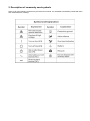
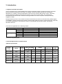
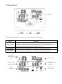
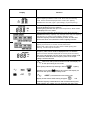
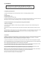
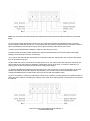
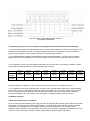
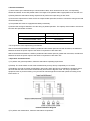
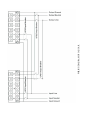
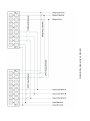
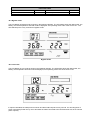
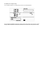
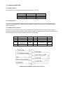
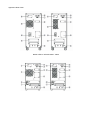
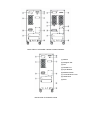
UPS
JAGUAR / LEOPARD
6/20 kVA
Sinercom S.r.l.
Headquarter: Via Alessandro Dudan 9- 00143 Rome (RM) - Italy
tel. +39.06.79800323 fax +39.06.79814644
Factory: Via Cascina Secchi 247/4b - 24040 Isso (BG) - Italy
tel. +39.0363.938231 fax +39.0363.998235
Commercial office: tel. +39.02.303126850/828 Fax +39.02.70051026
USER MANUAL
Please comply with all warnings and operating
instructions in this manual and on the unit strictly.
Save this manual properly.
Do not operate this unit before reading through all safety
information and operating instructions carefully.
1. IMPORTANT SAFETY INSTRUCTION
1.Safety and EMC instructions
Please read carefully the following user manual and the safety instructions before installing the unit or using the
unit!
1.1 Installation
■Condensation may occur if the UPS is moved directly from a cold to a warm environment. The UPS must be
absolutely dry before being installed. Please allow an acclimatization time of at least two hours.
■ Do not install the UPS near water or in damp environment.
■ Do not install the UPS where it would be exposed to direct sunlight or near heat.
■ Do not block ventilation openings in the UPS’s housing.
■ Do not connect appliances or items of equipment which would overload the UPS (e.g. laser printers, etc) to the
UPS output.
■ Place cables in such a way that no one can step on or trip over them.
■UPS has provided earthed terminal, in the final installed system configuration, equipotential earth bonding to
the external UPS battery cabinets.
■ An integral single emergency switching device which prevents further supply to the load by the UPS in any
mode of operation should be provided in the building wiring installation.
■ An appropriate disconnect device as short-circuit backup protection should be provided in the building wiring
installation.
■ For three-phase equipment connection to an IT power system, a four-pole device which disconnect all phase
conductors and the neutral conductor should be provided in the building wiring installation.
■ This is permanently connected equipment , it must be installed by qualified maintenance personnel.
■ Earth connection essential before connecting to the building wiring terminal.
1.2 Operation
■ Do not disconnect the earth conductor cable on the UPS or the building wiring terminals in any time since this
would cancel the protective earthing of the UPS system and of all connected loads
■ The UPS output terminal block may be electrically lived even if the UPS system is not connected to the
building wiring terminal.
■ In order to fully disconnect the UPS, first press the OFF button, then disconnect the mains lead.
■ Ensure that no liquid or other foreign objects can enter the UPS.
■ The UPS can be operated by any individuals with no previous experience.
1.3 Maintenance, servicing and faults
■ The UPS operates with hazardous voltages. Repairs may be carried out only by qualified maintenance
personnel.
■ Caution - risk of electric shock. Even after the unit is disconnected from the mains power supply (building
wiring terminal), components inside the UPS are still connected to the battery which are potentially dangerous.
■ Before carrying out any kind of service and/or maintenance, please disconnect the batteries. Verify that no
current is present and no hazardous voltage exists in the capacitor or BUS capacitor terminals.
■ Batteries must be replaced only by qualified personnel.
■Caution - risk of electric shock. The battery circuit is not isolated from the input voltage. Hazardous voltages
may occur between the battery terminals and the ground. Verify that no voltage is present before servicing!
■ Batteries have a high short-circuit current and pose a risk of shock. Take all precautionary measures specified
below and any other measures necessary when working with batteries:
-remove all jewellery, wristwatches, rings and other metal objects
- use only tools with insulated grips and handles.
■ When changing batteries, replace with the same quantity and the same type of batteries.
■ Do not attempt to dispose of batteries by burning them. It could cause explosion.
■ Do not open or destroy batteries. Effluent electrolyte can cause injury to the skin and eyes. It may be toxic.
■ Please replace the fuse only by a fuse of the same type and of the same amperage in order to avoid fire
hazards.
■ Do not dismantle the UPS, except qualified maintenance personnel.
1.4 Transport
■ Please transport the UPS only in the original packaging (to protect against shock and impact).
1.5 Storage
■ The UPS must be stockpiled in the room where it is ventilated and dry.
2. Description of commonly used symbols
Some or all of the following symbols may be used in this manual. It is advisable to familiarize yourself with them
and understand their meaning:
3. Introduction
3.1 System and model description
The On-Line-Series is an uninterruptible power supply incorporating double-converter technology. It provides
perfect protection specifically for strict load. The double-converter principle eliminates all mains power
disturbances. A rectifier converts the alternating current from the socket outlet to direct current. This direct
current charges the batteries and powers the inverter. In the event of power failure, the maintenancefree batteries power the inverter. Thus the inverter generates a sine wave AC power, which permanently
supplies the loads.
Designed with the proven on-line, double conversion architecture, this series of UPS offers the greatest degree
of availability in power protection and provides continuous high-quality AC power to connect strict load, especially
for the basic equipments in some areas as: finance, communication, government, traffic, manufacture,
education and so on.
This manual is applicable to the following models:
Type
Standard
Long back up
time
6kVA UPS
10kVA UPS
10kVA UPS
10kVA UPS
15kVA UPS
3kVAS UPS
Model
JAGUAR 6000
JAGUAR 10000
LEOPARD 10000
JAGUAR/LEOPARD 1000XL
LEOPARD 15000XL
LEOPARD 20000XL
Remark
inbuilt
inbuilt
inbuilt
External battery bank
External battery bank
External battery bank
“XL”Model: Long backup time
3.2 Product Specification and Performance
1)General specification
Power
Rating
6KVA/4.8KW
10KVA/8KW
10KVA/8KW
15KVA/12W
20KVA/16W
Model
JAGUAR
6000
JAGUAR
10000
LEOPARD
10000
LEOPARD
15000XL
LEOPARD
20000XL
Frequ
ency
(Hz)
50/60
50/60
50/60
50/60
50/60
Input(full load)
Voltage
(176-276)
VAC
(176-276)
VAC
(304-478)
VAC
(304-478)
VAC
(304-478)
VAC
Current
Output
Voltage
Dimensions
(W*D*H) m
Weight
(kg)
Current
31max 220V/230V
27A
248×500×616
57
50max 220V/230V
45A
248×500×616
67
50max 220V/230V
45A
248×500×885
88
75max 220V/230V
68A
248×500×616
35
100max 220V/230V
91A
248×500×616
35
2)Electrical performance
INPUT
Model
JAGUAR 6000/10000
LEOPARD 10000/20000
Power Factor
Voltage
Frequency
Single-phase
220VAC - 230VAC
Three-phase
380VAC/220 VAC
380VAC/230 VAC
50/60Hz±5%
(adjustable)
>0.99(Full load)
50/60Hz±5%
(adjustable)
>0.95(Full load)
OUTPUT
Voltage
regulation
±1%
Power
factor
Frequency tolerance
0.8
Synchronized
46-54Hz in Line mode
(AC mode) ±1% of
normal frequency in
Battery mode
Distortion
Overload capacity
Current
crest ratio
THD<2%
Full load
(Linear load)
105%-125% load
transfers to bypass
mode after 1minutes
>130% load
transfers to bypass
mode after 30second
3:1
maximum
3) Operating Environment
Temperature
Humidity
Altitude
Storage temperature
0 C-40 C
<95%
<1000m
0 C-40 C
Note: if the UPS is installed or used in a place where the altitude is bove than 1000m, the output power must be
derated in use, please refer to the following:
Altitude (M)
1000
1500
2000
2500
3000
3500
4000
4500
5000
Derating Power
100%
95%
91%
86%
82%
78%
74%
70%
67%
4. Display Panel
LCD Screen
On/Off Button
Select-Button
Enter-Button
T
he following table describes the function of the button switches of the front panel.
Button
ON/OFF Button
Select Button
Enter Button
Function
This button has two functions:
- Turning on the UPS system: By pressing this button the UPS system turns on.
- Shut off the UPS system: When mains power is normal, the UPS System switches to
Bypass mode by pressing OFF button , and the inverter is off .
if the ups system is in bypass mode or self-test mode, the output ,frequency could be
selected by pressing Select button, and confirmed by pressing Enter button.
if the ups system is in bypass mode or self-test mode, the output ,frequency could be
selected by pressing Select button, and confirmed by pressing Enter button.
Mode/Fault/
Warni-ng code
Set type
Load Information
Battery Voltage/
UPS temperature
Input/output voltage and
frequency
information
Battery
information
Indication of UPS
work mode
Display
Function
FAULT lighting indicates mode code, fault code and warning
code, which could be displayed from 0 to99 ,SET lighting
indicates the set code, type V (set voltage), F (set frequency)
BATTERY lighting indicates the battery voltage value, which
could be displayed from 0 to 999Vdc;
TEMP lighting indicates the ups inside temperature, which could
be displayed from 0 to 999℃
(The two items alternate displayed once every three seconds.)
indicates the battery capacity. For example: 25% and 50% lighting
synchronous, it means current battery capacity is 50%.
LOW BAT lighting indicates the battery is weak, and the UPS
should shut down soon,BATTERY FAULT lighting indicates
indicates the present load value. For example: 25% and 50%
lighting synchronous, it means current load is 50%.
When load 100% lighting and the OVER LOAD lighting with
warning, it means ups in overload
Indicates ups input voltage value, output voltage value, output
frequency value, which could be displayed from 0 to 999VAC
(The four items alternate displayed once every three seconds.)
208, 220 ,230,240VAC The four value of the output voltage could
be selected, 50/60HZ the two frequency value of the output
voltage could be selected.
indicates have mains power and when mode code display 02
that mean the ups working in Line mode.
ECO lighting indicates ups working in ECO Mode.
Lighting
indicates ups charging,
lighting and mode code display 03
that mean the ups working in battery mode.
and
lighting coinstantaneous and mode code
display 03 that means UPS working in Bypass mode.
and
LOW BAT lighting coinstantaneous and UPS with warning that
means Battery low voltage, the ups will would shut down soon.
5. Installation
the system may be installed and wired only by qualified
electricians in accordance with applicable safety regulations!
5.1 Unpacking and Inspection
1) Unpack the packaging and check the package contents. The shipping package contains:
● A UPS
● A user manual
● A communication cable
● A battery cable (for XL series only)
2) Inspect the appearance of the UPS to see if there is any damage during transportation. Do not turn on the unit
and notify the carrier and dealer immediately if there is any damage or lacking of some parts.
5.2 Input and output power cords and protective earth ground installation
1. Notes for installation
1) The UPS must be installed in a location with good ventilation, far away from water, inflammable gas and
corrosive agents.
2) Ensure the air vents on the front and rear of the UPS are not blocked. Allow at least 0.5m of space on each
side.
3) Condensation to water drops may occur if the UPS is unpacked in a very low temperature environment. In this
case it is necessary to wait until the UPS is fully dried inside out before proceeding installation and use.
Otherwise there are hazards of electric shock.
2. Installation
Installation and wiring must be performed in accordance with the local electric code and the following instructions
by Professional personnel. or safety, please cut off the mains power switch before installation. The battery
breaker also needs to be cut off if it is a long backup time model (“XL” model).
1) Open the terminal block cover located on the rear panel of the UPS, please refer to the appearance diagram.
2) For JAGUAR 6000 UPS, it is recommended to select the UL1015 10AWG (6mm2) wire or other insulated wire
which complies with AWG Standard for the UPS input and output wirings.
3) For JAGUAR/LEOPARD 10000 UPS, it is recommended to select the UL1015 8AWG (10mm2) wire or other
insulated wire which complies with AWG Standard for the UPS input and output wirings.
4) For LEOPARD 15000/20000 UPS,it is recommended to select the UL1015 6AWG (25mm2) wire or other
insulated wire which complies with AWG Standard for the UPS input and output wirings.
Note: Do not use the wall receptacle as the input power source for the UPS, as its rated current is less than the
UPS’s maximum input current. Otherwise the receptacle may be burned and destroyed.
5) Connect the input and output wires to the corresponding input
and output terminals according to the following diagram.
Note: you must make sure that the input and output wires and the input and output terminals are connected
tightly.
6) The protective earth ground wire refers to the wire connection between the equipment which consumes
electric equipment and the ground wire. The wire diameter of protective earth ground wire should be at least as
above mentioned for each model and green wire or green wire with yellow ribbon wire is used.
7) After having completed the installation, make sure the wiring is correct.
8) Please install the output breaker between the output terminal and the load, and the breaker should with
leakage current protective function if necessary.
9) To connect the load with the UPS, please turn off all the loads first, then perform the connection and finally
turn on the loads one by one.
10) No matter the UPS is connected to the utility power or not, the output of the UPS may have electricity. The
parts inside the unit may still have hazardous voltage after turning off the UPS. To make the UPS have no
output, power off the UPS, and then disconnect the utility power supply.
11) Suggest charging the batteries for 8 hours before use. After connection, turn the input breaker in the “ON”
position, the UPS will charge the batteries automatically. You can also use the UPS immediately without
charging the batteries first, but the backup time may be less than the standard value.
12) If it is necessary to connect the inductance load such as a monitor or a laser printer to the UPS, the start-up
power should be used for calculating the capacity of the UPS, as its start-up power consumption is too big when
it is started.
Input and Output Terminal Block wiring diagram of
JAGUAR 6000/10000
Input and Output Terminal Block wiring diagram of
LEOPARD 10000/20000
5.3 Operating procedure for connecting the long backup time model UPS with the external battery
1. The nominal DC voltage of external battery pack is 192VDC. Each battery pack consists of 16 pieces of 12V
maintenance free batteries in series. To achieve longer backup time, it is possible to connect multi-battery
packs, but the principle of “same voltage, same type” should be strictly followed.
2. For JAGUAR 6000XL/10000XL and LEOPARD 10000XL/15000XL/20000XL, The procedure of installing
battery bank should be omplied with strictly. Otherwise you may encounter the hazardous of electric shock..
1) A DC breaker must be connected between the battery pack and the UPS. The capacity of breaker must be
not less than the data specified in the general specification as follow.
Model
Battery
voltage
Battery
current
JAGUAR
6000
JAGUAR
6000XL
JAGUAR
10000
JAGUAR
10000XL
LEOPARD
10000
LEOPARD
10000XL
LEOPARD
15000XL
LEOPARD
20000XL
192VDC
192VDC
192VDC
192VDC
192VDC
192VDC
192VDC
192VDC
34A max
34A max
56A max
56A max
46A max
46A max
70A max.
102A max
2) Set the battery pack breaker in “OFF” position and connect the 16 pieces of batteries in series.
3. To complete the connection by plugging the connector of the external battery cable into the external battery
socket of the UPS. Do not attempt to connect any loads to the UPS now. You should connect the input power
wire to the right position first. And then set the breaker of the battery pack in the “ON” position. After that
set the input breaker in the “ON” position. The UPS begins to charge the battery packs at the time.
5.4 Parallel operation
1. Brief introduction of the redundancy
N+X is currently the most reliable power supply structure. N represents the minimum UPS number that the total
load needs; X represents the redundant UPS number, i.e. the fault UPS number that the system can handle
simultaneously. The bigger the X is, the higher reliability of the power system is. For occasions where
reliability is highly required, N+X is the optimal mode. As long as the UPS is equipped with parallel cables, up to
3 of them can be connected in parallel to realize output power sharing and power redundancy.
2. Parallel installation
1) Users need to opt a standard 25-pin communication cable, which should have 25 cores, corresponding
stitches and shield, as the UPS parallel cable. The length of the parallel cable is appropriate to be less than 3 m.
2) Strictly follow the stand-alone wiring requirement to perform the input wiring of each UPS.
3) Connect the output wires of each UPS to an output breaker panel first, and then connect the wiring to the load
via the breaker panel.
4) The parallel UPS must be equipped with battery individually.
5) Please refer the figure followed to see the wiring of parallel operation. The capacity of the breaker must be not
less than the specification as follow.
Model No.
Capacity of breaker
JAGUAR 6000
≥40A/250VAC
JAGUAR/LEOPARD 10000
≥60A/250VAC
LEOPARD 15000/20000
≥100A/250VAC
*The requirement of the output wiring is as follows:
●When the distance between the UPSs in parallel and the breaker panel is less than 20 meters, the difference
between the wires of input & output of the UPSs is required to be less than 20%;
●When the distance between the UPSs in parallel and the breaker panel is greater than 20 meters, the ifference
between the wires of input & output of the UPSs is required to be less than 10%.
3. Operation and maintenance
1) To perform the general operation, follow the stand-alone operating requirement.
2) Startup: The units transfer to INV mode simultaneously as they start up sequentially in Line mode.
3) Shutdown: the units shut down sequentially in INV mode. When the last one completes the shutdown action,
each unit will shut down the inverter simultaneously and transfer to Bypass mode. It is easy to operate the
equipment, with no previous training. You just need to read through this manual and operate according to the
instructions in it.
Parallel Installation Diagram
4) To perform the maintenance, follow the stand-alone requirement
WIRING DIAGRAM OF JAGUAR
WIRING DIAGRAM OF LEOPARD
6. Operation
6.1 Operation Mode
1. Turn on the UPS with utility power supplied (in Line mode)
1) After you make sure that the power supply connection is correct, and then set the breaker of the battery pack
in the “ON” position (this step only for long backup time model), after that set the input breaker in the “ON”
position. At this time the fan rotates and the UPS supplies power to the load via the bypass. The UPS operates
in Bypass mode, the mode code is “01”.
2) To power on the UPS by simply pressing the ON button continuously for more than 1 second, the buzzer will
beep once.
3) A few seconds later, the UPS turn into Line mode, and the mode code is “02”. If the utility power is abnormal,
the UPS will operate in Battery mode without output interruption of the UPS.
2. Turn on the UPS with no utility power supplied (in Battery mode)
1) After you make sure that the breaker of the battery pack is in the “ON” position (this step only for long backup
time model).
2) Press the ON button continuously for more than 1 second to power on the UPS, and the buzzer will beep
once, UPS operates in No Output mode, the mode code is “00”.
3) A few seconds later, the UPS turn into Battery mode, and the mode code is “03”.
3. Turn off the UPS with utility power supplied (in Line mode)
1) To turn off the inverter of the UPS by pressing the OFF button continuously for more than 1 second, and the
buzzer will beep once. The UPS will turn into Bypass mode.
2) Upon completion of the above to turn it off, output of electric current of the UPS is still present. In order to cut
off the output from the UPS, simply cut off the utility power supply, a few seconds later, there are not any display
is shown on the display panel and no voltage output is available from the UPS output.
4. Turn off the UPS with no utility power supplied (in Battery mode)
1) To power off the UPS by pressing the OFF button continuously for more than 1 second, and the buzzer will
beep once.
2) When being powered off, the UPS will turn into No Output mode. Finally not any display is shown on the
display panel and no voltage is available from the UPS output.
Suggestions: Please turn off the connected loads before turning on the UPS and turn on the loads one by one
after the UPS is working in INV mode. Turn off all of the connected loads before turning off the UPS.
7. Battery Maintenance
● This series UPS only requires minimal maintenance. The battery used for standard models are value regulated
sealed lead-acid maintenance free battery. These models require minimal repairs. The only requirement is to
charge the UPS regularly in order to maximize the expected life of the battery. When being connected
to the utility power, whether the UPS is turned on or not, the UPS keeps charging the batteries and also offers
the protective function of overcharging and over-discharging.
● The UPS should be charged once every 4 to 6 months if it has not been used for a long time.
● In the regions of hot climates, the battery should be charged and discharged every 2 months. The standard
charging time should be at least 12 hours.
● Under normal conditions, the battery life lasts 2 to 4 years. In case if the battery is found not in good condition,
earlier replacement should be made. Battery replacement should be performed by qualified personnel.
● Replace batteries with the same number and same type of batteries.
● Do not replace the battery individually. All the batteries should Be replaced at the same time following the
instructions of the battery supplier.
● Normally, the batteries should be charged and discharged once every 4 to 6 months. Charging should begin
after the UPS shuts down automatically in the course of discharging, the standard charging time for the standard
UPS should be at least 12 hours.
8. Notes for Battery Disposal and Battery Replacement
1) Before disposing of batteries, remove conductive jewelry such as necklace, wrist watches and rings.
2) If it is necessary to replace any connection cables, please purchase the original materials from the authorized
distributors or service centers, so as to avoid overheat or spark resulting in fire due to insufficient capacity.
3) Do not dispose of batteries or battery packs in a fire, they may explode.
4) Do not open or mutilate batteries, released electrolyte is highly poisonous and harmful to the skin and eyes.
5) Do not short the positive and negative of the battery electrode, otherwise, it may result in electric shock or fire.
6) Make sure that there is no voltage before touching the batteries. The battery circuit is not isolated from the
input potential circuit. There may be hazardous voltage between the battery terminals and the ground.
7) Even though the input breaker is disconnected, the components inside the UPS are still connected with the
batteries, and there are potential hazardous voltages. Therefore, before any maintenance and repairs work is
carried out, switch off the breaker of the battery pack or disconnect the jumper wire of connecting between the
batteries.
8) Batteries contain hazardous voltage and current. Battery maintenance such as the battery replacement must
be carried out by qualified personnel who are knowledgeable about batteries. No other persons should handle
the batteries.
10. Operating mode for all models
The different codes could be displayed on the LCD screen corresponding to their own operating modes, and
they are illustrated as the follow:
Operating mode
Code
Operating mode
Code
Mode Code Table
Parallel Mode
Bypass mode
Line mode
02
01
02
Battery mode
Battery test mode
03
04
Warning Code Table
ID Loss
Fan Error
Battery Low
21
10
12
Charger Bad
IP Fuse Open
13
11
Fault Code Table
Bus Fault
Overload Fault
Other
05
07
09
Inverter Fault
Over temperature Fault
06
08
15
10.1 Bypass mode
The LCD display in Bypass mode is shown in the following diagram. The information about the utility power, the
battery, the UPS temperature and load could be displayed. The operating mode code of the UPS is “01”. The
UPS will beep once every 2 minutes in Bypass mode.
Bypass mode
10.2 Line mode
The LCD display in Line mode is shown in the following diagram. The information about the utility power, the
battery, the temperature and load could be displayed, The operating mode code of the UPS is “02”.
Line mode
If output overloaded, the load percent is shown and alarm will keep twice every second. You should get rid of
some unnecessary loads one by one to decrease the loads connected to the UPS less than 90% of its nominal
power capacity.
10.3 Battery mode
The LCD display in Battery mode is shown in the following diagram. The information about the utility power, the
battery, the temperature and load could be displayed. The operating mode code of the UPS is “03”.
1) When the UPS is running in Battery mode, the buzzer beeps once every 4 seconds. If the ENTER button on
the front panel is pressed for more than 1 second again, the buzzer will stop beeping (in silence mode).
Battery mode
10.4 Self-Test mode
The LCD display in Battery mode is shown in the following Diagram.The information about the utility power, the
battery, emperature and load could be displayed. The operating mode code of the UPS is “04”.
Self-Test mode
10.5 Parallel mode
The LCD display in parallel mode is shown in the following diagram. When the UPS operating in parallel mode,
the operating mode code of the UPS is “P2”.
Parallel mode
10.6 Warning mode
The LCD display in warning mode is shown in the following diagram. the symbol “WARNING” is shown instead in
code display.
Warning mode
10.7 Fault mode
The LCD display in fault is shown in the following diagram. The symbol “MODE” not be shown and the symbol
“FAULT” is shown instead in code display.
Fault mode (Bus Fault)
10.8 Set Mode
The LCD display in voltage set is shown in the following diagram.
Set Voltage
The LCD display in Frequency set is shown in the following diagram.
10.9 Battery Low voltage warning
The LCD display in Battery Low voltage warning is shown in the following diagram.
Notice:When Battery low voltage or short back-up time, both low-voltage marker and clock marker
would bright synchronously
10.10 Battery Low voltage warning
The LCD display in Battery Low voltage warning is shown in the following diagram.
Note: The above all diagrams: temperature, battery voltage, Input voltage, input frequency, output
voltage, output frequency would alternately displayed in each mode (once every three seconds)
11. Communication Port
11.1 RS232 Interface
The following is the pin assignment and description of DB-9 connector.
Pin #
2
3
5
Description
TXD
RXD
GND
I/O
Output
Input
Input
11.2 Intelligent slot
This series is equipped with an intelligent slot for Webpower (optional accessory) or other optional card to
achieve remote management of the UPS through internet / intranet. Please contact your local distributor for
further information.
11.3 AS400 Interface (Option)
Except for the communication protocol as mentioned above, this series UPS has AS400 card (an optional
accessory) for AS400 communication protocol. Please contact your local distributor for details. The following is
the pin assignment and description of DB-9 connector in AS400 card.
Pin #
1
2
3
4
5
Description
UPS Fail
Summary Alarm
GND
Remote
Shutdown
Common
I/O
Output
Output
Input
Pin #
6
7
8
Description
Bypass
Battery Low
UPS ON
I/O
Output
Output
Output
Input
9
Line Loss
Output
Input
DB-9 Interface of AS400 communication protocol
Appendix1:Rear Panel
BACK VIEW of JAGUAR 6000 / 10000
BACK VIEW of LEOPARD 10000XL/15000XL/20000XL
(1) RS232
(2) Inteligent Solt
(3) Fan
(4) Parallel Port
(5) Input Breaker
(6) Maintain Switch
(7) Terminal Block Cover
(8) Cable Rack
(9) EPO
BACK VIEW of LEOPARD 10000