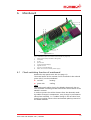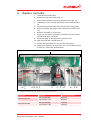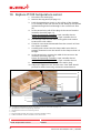
1
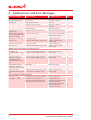
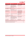
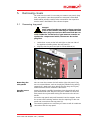
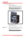
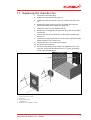
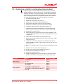
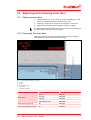
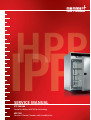
SERVICE MANUAL
IPP 200-500
Cooled incubator with Peltier technology
HPP 108
Constant Climate Chamber with humidification
Contents
1.
1.1
1.2
1.3
1.4
About this guide
Purpose and target group
Related documents
Tools needed
Manufacturer address and
customer service
4
4
4
4
14.
4
15.
2.
Safety regulations
5
3.
Finding Errors and
Error Messages
6
15.1
15.2
15.3
15.4
4.
4.1
4.2
Overview
Construction
Control unit
8
8
10
5.
5.1
5.2
Removing covers
Removing top panel
Removing the rear panel
11
11
12
6.
6.1
Mainboard
Check switching function of
mainboard
Replace fuses
Replace mainboard
13
6.2
6.3
13
14
14
7.
Replacing the switched mode
power supply
8.
Replace main switch module with
the push/turn control
16
9.
Replace controller
17
10.
Replace Pt100 temperature
sensor
18
11.
Replacing the chamber fan
19
12.
Removing the fan from the
rear panel
21
13.
Replacing a Peltier
cooling/heating module
23
Service IPP 200-500/HPP 108 | 10/2008
15
Adjusting and removing
inner door
14.1 Adjusting inner door
14.2 Removing the inner door
Installing, removing and
adjusting door
Removing the door
Installing the door
Adjusting the door
Removing and installing
the door lock
16. Replacing seals
16.1 Replacing door seal
16.2 Replacing the chamber
seal and the cage seal
17.
25
25
25
26
26
26
27
28
30
30
30
Replacing the interface module 32
18.
Humidification and/or
dehumidification does
not work properly
33
18.1 Humidification is not
working properly
33
18.1.1 Replac steam generator
35
18.1.2 Replacing the pump
36
18.2 Dehumidification is not
working properly
36
18.2.1 Replace fan and dehumidification Peltier module
37
18.2.2 Replace the dehumidification power supply unit 38
18.3 Replace control module
39
18.4 Replacing the humidity sensor 40
19.
19.1
19.2
19.3
19.4
Circuit diagrams
Legend
IPP 200/300/400
IPP 500
HPP 108
42
42
43
44
45
3
1. About this guide
1.1 Purpose and target group
This guide describes the service and repair work available for
cooling incubators of types IPP 200–500 and constant climate
chambers of type HPP 108. It is intended exclusively for use by
electrical technicians who are familiar with safety regulations for
electrical engineering.
1.2 Related documents
Apart from this service guide, the information and regulations in
the user manual for the respective appliance must also be observed for all service and repair work.
Please refer to the circuit diagrams at the end of this guide for all
work on the electrical system.
1.3 Tools needed
The following tools and equipment are required to perform the
work described in this guide:
► Torx screwdriver sizes 8 and 10
► Phillips screwdriver size 1
► Wire-cutting pliers
► Flat pliers to remove the connection cable
► Allen key 2 mm for door hinge,
1.5 mm for humidity sensor (for HPP 108)
► Multimeter with voltage and resistance measuring range
► Cable ties
► Adhesive tape to label cables and components
1.4 Manufacturer address and customer service
MEMMERT GmbH + Co. KG
Postfach 17 20
91107 Schwabach, Germany
Äußere Rittersbacherstr. 38
91126 Schwabach
Germany
Phone:
+49 (0) 09122 / 925-0
Fax: +49 (0) 09122 / 14585
E-mail: [email protected]
Internet: www.memmert.com
Customer Service:
Phone:
+49 (0) 09122/925-128
and: +49 (0) 09122/925-126
E-mail: [email protected]
For service enquiries, please always specify the appliance number
on the nameplate.
© 2008 Memmert GmbH + Co. KG
Date 10/2008
We reserve the right to make changes
4
Service IPP 200-500/HPP 108 | 10/2008
2. Safety regulations
Danger!
After removing covers, voltage-carrying parts
may be exposed if the mains plug has not
been disconnected. Any work that involves
opening the appliance may only be performed
by trained electricians who are familiar with
the safety regulations for electrical engineering.
Caution!
When dismantling the appliance you could be
injured on sharp (unprocessed) metal edges.
You should wear gloves.
Please also observe the safety regulations in
the operating instructions for the respective
appliance.
After all maintenance or repair work, the appliance must be subject to a function test. The appliance must not be left unattended
until it has reached the steady state.
If the fault or malfunction cannot be rectified by the repair work:
Contact the manufacturer.
Service IPP 200-500/HPP 108 | 10/2008
5
3. Finding Errors and Error Messages
Error description
Cause of error
Rectifying errors
Page
Fuse 100 mA
(200 mA/115 V) faulty
Check fuse, replace if
necessary
14
Appliance fuse 15 A faulty
Check fuse, replace if
necessary
14
13
General faults
Controller display does
not light up
Mainboard faulty
Replace mainboard
Temperature cannot be
adjusted and
appliance can in general
not be operated with the
push/turn control
Appliance "locked" by UserID card
Undo lock with UserID card
Push/turn control faulty
Replace main switch module
with push/turn control
16
Cooling fan on rear wall
does not turn
- cooling fan faulty
- switched mode power supply faulty
- replace cooling fan
- replace switched mode
power supply
21
15
Cooling fan in interior
does not turn
- cooling fan faulty
- switched mode power supply faulty
- replace cooling fan
- replace switched mode
power supply
19
15
Malfunctions in the heating and cooling function
Red LED on the
mainboard does not light
up
- switched mode power supply faulty
- contact element MOSFET faulty
replace switched mode
power supply
15
When changing from
heating to cooling,
the red LED on the
mainboard does not go
out
- switched mode power supply faulty
- contact element MOSFET faulty
replace switched mode
power supply
15
When switching from
Relay faulty
heating to cooling, the
relay does not switch over
Replace mainboard
13
Green LED on the
mainboard does not light
up
replace switched mode
power supply
15
- switched mode power supply faulty
- contact element MOSFET faulty
Error messages in monitoring display
Caution – icon
is flashing
6
Monitoring controller has switched
off heater, since temperature
difference between operating and
monitoring controller is too small
Increase temperature
difference between
monitoring temperature and
working temperature.
Replace Pt100 temperature
sensor of monitoring
controller if necessary
18
Service IPP 200-500/HPP 108 | 10/2008
Error description
Cause of error
Rectifying errors
Page
Error message "E-3"
alternates with display of
temperature
Pt100 temperature sensor of
monitoring controller faulty.
Monitoring controller is working
in emergency mode with the
temperature value of the Pt100
temperature sensor from the
operating controller
Replace Pt100 temperature
sensor of the monitoring
controller on plug J3
18
Error messages in timer display
Error message "E-0"
Serious configuration error
(e.g. incorrect cabinet type or wrong
temperature range)
Replace controller
17
Error message "CONF" (is
displayed for only 10 sec.
after switching on)
Checksum error (error when saving
set values, e.g. air turbine speed)
The error can be rectified
by the controller after a set
value parameter has been
saved again. If the error
should continue occurring,
or cannot be rectified,
replace the controller
17
Error message "E-L1" in
the timer display
Communication with the mainboard
interrupted
Check connection cable,
replace mainboard if
necessary
13
Error messages in temperature display
Error message "E-3"
alternates with display of
monitor
Pt100 temperature sensor of
Replace Pt100 temperature
operating controller faulty. Operating sensor of the operating
controller is working in emergency
controller on plug J4
mode with the temperature value of
the Pt100 temperature sensor from
the monitoring controller
18
Error message "E-1"
Mainboard actuator Triac faulty
Replace mainboard
13
Error message "E-2"
Mainboard faulty
Replace mainboard
13
Malfunctions of the humidifier and/or dehumidifier (only for the constant climate chambers HPP 108)
Neither humidification nor dehumidification are working properly
33
Dehumidification works, humidification doesn't work
33
Humidification works, dehumidification doesn't work
36
Service IPP 200-500/HPP 108 | 10/2008
7
4.
Overview
4.1
Construction
1
2
9
8
10
11
3
7
5
4
6
Fig. 1: Construction (shown in figure: Maximum fittings for HPP 108; the actual fittings may vary, depending
on the appliance type)
8
Service IPP 200-500/HPP 108 | 10/2008
Item Designation
see also page
1
Top panel
11
2
Rear panel
12
3
Right-side panel
11
4
Door
26
5
Inner glass door
25
6
Fan cover, right1
19
7
Fan cover, left
19
8
Left-side panel
9
Cover of left Peltier heating/cooling module
10
Cover of dehumidification Peltier module2
11
Cover of right-hand Peltier heating/cooling module
1
11
21
1
37
1
21
only for types IPP 500 and HPP 108; types IPP 200-400 have just one interior fan and one Peltier heating/
cooling module on the rear side
1
2
only for constant climate chambers HPP 108
Service IPP 200-500/HPP 108 | 10/2008
9
4.2
Control unit
(see also circuit diagrams from page 42).
The control unit can be reached after the top panel has been removed (see page 11).
1
2
3
4
5 6
7
Fig. 2: Control unit IPP 200/300/400
2
10
7
3
4
5
7
9
8
Fig. 3: Control unit IPP 500/HPP 108
1
2
3
4
5
6
7
Main connection terminal
Mainboard (see page 13)
Controller (see page 17)
Chipcard reader
Main switch (see page 16)
Feed-through for temperature sensor Pt100 (see page 18)
Switched mode power supply(ies) (see page 15)
Only for HPP 108:
8 Pump for humidification (see page 36)
9 Control module for humidification (page 39)
10 Power supply unit for humidification (page 38)
10
Service IPP 200-500/HPP 108 | 10/2008
5.
Removing covers
For some service work it is necessary to remove case panels (top,
side, rear panels). How these panels are removed is described
below. What panel(s) need(s) to be removed for the respective
service work is described in the relevant chapter.
5.1
Removing top panel
Danger!
After removing the top panel, voltage-carrying
parts in the control unit may be exposed if the
mains plug has not been disconnected. Do not
reach inside the control unit. If you want to examine or
replace the components inside, disconnect the mains
plug first.
1.
2.
Undo the 4 screws to the left and right on the rear side of
the appliance holding down the top panel (1).
Slightly raise the panel and pull it out backwards (2).
2
1
3
Fig. 4: Removing the top and side panels
Removing the
side panels
Put the covers
back on
You can now also remove the left and/or right side panel. They
are not screwed down, and can simply be pulled out by pulling
upwards (3). Make sure when doing this that they do not jam,
and disconnect the PE conductor connection.
Insert side panels carefully from above into the guide rails and
push downwards until they slot into place. Make sure that the
side panels do not jam when doing this. Reconnect the PE conductor.
Put on the top panel and push forwards into the support. Insert
the screws with retaining washers into the openings in the rear
panel and screw down the top panel (1).
The retaining washers are necessary to create a safe PE conductor
connection with the top panel.
Service IPP 200-500/HPP 108 | 10/2008
11
5.2
Removing the rear panel
1.
2.
3.
4.
Disconnect the mains plug.
Remove the top panel (see page 11).
Unscrew the cover grid of the Peltier module (IPP 200–400)
or of the two Peltier modules (IPP 500/HPP 108) on the rear
side (1).
In addition for the constant climate chamber HPP 108: Unscrew the cover grid of the dehumidification Peltier module
and of the steam generator in the centre (2).
Pull rear panel upwards out of the appliance (3). Make sure
that the rear panel does not jam when doing this.
3
1
1
2
Fig. 5: Removing the rear panel
1
2
3
Put the rear panel
back on
1.
2.
12
Unscrew the cover grid of the Peltier module/s
Unscrew the cover grid of the dehumidification Peltier module and of the
steam generator (only for the HPP 108).
Pull out the rear panel of the casing upwards
Insert the rear panel carefully from above into the guide rails
and push downwards until it slots into place. Make sure that
the rear panel does not bend when doing this.
Screw on the grid covers of the Peltier modules on the right
and left (1).
In addition for the constant climate chambers HPP 108:
Screw on the cover grid of the dehumidification Peltier module and of the steam generator in the centre (2).
Service IPP 200-500/HPP 108 | 10/2008
6.
Mainboard
8
7
6
1 2
5
3
4
Fig. 6: Mainboard (see also control unit overview on page 10)
1
2
3
4
5
6
7
8
6.1
Heat up LED (red)/cool down LED (green)
S 30 (fan)
Screw
Spacer bolt
S 28 (controller/display)
Appliance fuse
Fuse for controller/display
Main connection terminal power supply
Check switching function of mainboard
Remove the top panel to do this (see page 11).
The actual status of the actuator can be checked via the red and
green LED (1) on the mainboard:
► red LED:
heating
► green LED:
cooling
Note:
The heating and cooling icon in the display shows only the current controller actuating variable and not the actual status of the
MOSFET actuator.
In order to protect the Peltier element from the demands made
by sudden changes in temperature, every change in performance
takes place smoothly, i.e. a sudden change in the set value from
heating to cooling causes a slow and smooth polarity reversal of
the Peltier element.
Service IPP 200-500/HPP 108 | 10/2008
13
6.2
Replace fuses
The fuses for controller/display and appliance protection are located on the mainboard (see page13).
1. Disconnect the mains plug.
2. Remove the top panel (see page 11).
3. Measure the fuse resistance with a continuity tester. If the
fuse is in order the resistance should only be a few Ohms.
4. To replace the fuse, push an insulated flat screwdriver beneath the side of the fuse and lever it out of the mounting
bracket. Press the new fuse into the mounting bracket from
above.
► Appliance fuse:
15 A quick-blow 32 x 6.3 mm
(American)
► Fuse for controller/display:
100 mA slow-blowing
20 x 5 mm
200 mA slow-blowing
20 x 5 mm (115V)
Spare part
Variants
Appliance fuse 15 A
Fuse for controller/display
6.3
E02387
100 mA/230 V E02497
200 mA/115 V E01007
Replace mainboard
1.
2.
3.
4.
5.
6.
7.
8.
9.
Disconnect the mains plug.
Remove the top panel (see page 11).
Pull off all cables from the mainboard. Label unmarked cables
with adhesive tape to avoid confusion when reconnecting.
Undo 4 screws from the mainboard. Make sure that the
spacer bolts are not lost when doing this.
Remove the mainboard.
Insert a new mainboard and screw it tight with the spacer
bolts.
Reconnect the cable.
Put the top panel back on; plug in the mains plug.
Check that the appliance is working. If the fault persists: Contact the manufacturer.
Spare part
Mainboard
14
Spare part number
Variants
Spare part number
230 V
B04098
115 V
B04113
Service IPP 200-500/HPP 108 | 10/2008
7.
Replacing the switched mode power supply
1.
2.
3.
4.
5.
6.
7.
8.
Disconnect the mains plug.
Remove the top panel (see page 11).
Disconnect all the plugs on the switched mode power supply
and label them if necessary (1).
Undo the screws (4 screws) at the corners (2) and remove the
switched mode power supply.
Insert a new switched mode power supply and screw tight.
Reconnect the plug to the switched mode power supply.
Re-attach the top panel.
Connect the mains plug and subject the appliance to a function test. If the fault should persist or if it works incorrectly,
contact the manufacturer.
1
2
2
Fig. 7: Switched mode power supply
1
2
Connections
Screws
Spare part
Spare part number
Switched mode power supply
E04016
Service IPP 200-500/HPP 108 | 10/2008
15
8.
Replace main switch module with the push/turn
control
1.
2.
3.
4.
5.
6.
7.
8.
9.
10.
11.
12.
Disconnect the mains plug.
Remove the top panel (see page 11).
Pull off the push/turn control (1) forwards.
Remove the plugs (4-pin) (4) from the controller slot J2.
Undo the mounting bolts on left and right (2).
Slightly raise the main switch module and pull backwards.
Place new main switch module into the control panel.
Attach the module with two screws (2).
Connect the plug (4) to the controller slot J2.
Attach the push/turn control (1) at the front.
Put the top panel back on; connect the mains plug.
Switch on appliance and check the function of the new main
switch module and the push/turn control. If the error has not
been rectified: Contact the manufacturer.
4
3
1
2
Fig. 8: Main switch module (see also control unit overview on page 10)
1
2
3
4
16
Push/turn control
Mounting bolts (left and right)
Main switch
Plug (controller slot J2)
Spare part
Variants
Spare part number
Main switch module
230 V
B04425
Service IPP 200-500/HPP 108 | 10/2008
9.
Replace controller
1.
2.
3.
4.
Disconnect the mains plug.
Remove the top panel (see page 11).
Pull off the push/turn control to the front (see page 16).
Undo three screws (3) and remove the main switch module
(4).
5. Cut and remove both cable ties (2) with wire-cutting pliers.
6. Pull off and label the plugs of the respective controller slots
(Jx).
7. Remove controller (1) to the rear.
8. Insert new controller and fasten controller and main switch
module with three screws (3).
9. Reconnect plug to the respective controller slots.
10. Push the push/turn control back on.
11. Put the top panel back on; connect the mains plug.
12. Subject the appliance to a function test. If it should still work
incorrectly, contact the manufacturer.
1
J13 2
J4 J3 J11 3
3
4
3
J2
J9
2 J8
Fig. 9: Replace controller (see also control unit overview on page 10)
Spare part
Controller RS 232
Controller RS 485
Variants
Spare part number
IPP 200/300/400
B04279
IPP 500/HPP 108
B04281
IPP 200/300/400
B04280
IPP 500/HPP 108
B04282
Service IPP 200-500/HPP 108 | 10/2008
17
10. Replace Pt100 temperature sensor
1.
2.
3.
Disconnect the mains plug.
Remove the top panel (see page 11).
Push the temperature sensor on the ceiling of the chamber
(1,2) carefully to the rear and out of the clamp (3) and thread
upwards through the feed-through in the control unit floor
(4).
4. In the control unit, pull off the plug of the sensor from the
controller (see also page 17):
Sensor for operating controller: 4-pin controller slot J4
Sensor for monitoring controller: 4-pin controller slot J3
5. Cut through cable tie with wire-cutting pliers and remove
Pt100 sensor with cables.
6. Thread in new sensor downwards from the control unit into
the climate chamber.
7. Carefully push sensor into the clamp. Make sure that it is
properly mounted. Insert the sensor in the clamp so that it is
straight.
8. In the control unit, connect the cable of the sensor on the
controller (see also page 17):
Sensor for operating controller: 4-pin controller slot J4
Sensor for monitoring controller: 4-pin controller slot J3
9. Put the top panel back on, connect the mains plug.
10. Subject the appliance to a function test. If the fault should
persist/if it works incorrectly, contact the manufacturer.
5
4
3
1,2
1
2
Fig. 10: Replace temperature sensor (see also control unit overview on page 10)
1 Temperature sensor for operating controller
2 Temperature sensor for monitoring sensor
3 Clamp
4 Feed-through through the control unit floor/chamber ceiling
5 Cable connection to the controller in the control unit
Spare part
Spare part number
Pt100 temperature sensor
E04822
18
Service IPP 200-500/HPP 108 | 10/2008
11. Replacing the chamber fan
1.
2.
3.
Disconnect the mains plug.
Remove the top panel (see page 11).
Undo the screws of the fan cover (1); remove the fan cover
(2).
4. Remove the plug connector of the chamber fan from the
switched-mode power supply (see page 10).
5. Undo the screws of the chamber fan (3).
6. Remove the chamber fan (4) from the heat sink of the Peltier
module (5).
7. Place a new fan on the heat sink of the Peltier module and
screw it in.
8. Connect the plug connector of the fan to the switched-mode
power supply in the control unit.
9. Position the fan cover and screw it down.
10. Re-attach the top panel.
11. Reconnect the mains plug. Subject the appliance to a function test. If the fault should persist or if it works incorrectly,
contact the manufacturer.
5
3
1
4
2
Fig. 11: Replacing the chamber fan
1
2
3
4
5
Screws for the fan cover
Fan cover
Screws for the fan
Chamber fan
Heat sink for the Peltier module
Service IPP 200-500/HPP 108 | 10/2008
19
Spare part
Variants
Spare part number
Chamber fan IP54
all
B04004
IPP 200/300
E03995
IPP 400
E03994
IPP 500
E04656
Fan cover
HPP 108
20
left
E05401
right
E05402
Service IPP 200-500/HPP 108 | 10/2008
12. Removing the fan from the rear panel
Depending on the appliance model, there may be up to three
fans on the rear panel: one (IPP 200-400) or two (IPP 500/HPP)
fans for heating/cooling, one fan for dehumidification (only for
HPP). How to replace this is described on page 37. The description on this page refers to the removal of the fan(s) for heating/
cooling (see also overview diagram on page 8).
1. Disconnect the mains plug.
2. Remove the top panel (see page 11).
3. Remove the cover of the Peltier module (1).
4. Undo the mounting bolts of the fan (2).
5. Remove the fan cover grid (3).
6. Pull off the plug connector of the fan in the control unit.
7. Remove the fan (4) from the heat sink of the Peltier module
(5).
8. Screw on a new fan (4) with cover grid (3) to the heat sink of
the Peltier module (5).
9. Connect the plug connector of the fan in the control unit.
10. Remove the cover of the Peltier module (1).
11. Put the top panel back on and connect the mains plug.
12. Subject the appliance to a function test and check the fan to
see that it works. If the fault should persist or if it works
incorrectly, contact the manufacturer.
Service IPP 200-500/HPP 108 | 10/2008
21
6
5
2
3
4
3
1
Fig. 12: Remove the fan from the rear panel (actual view may differ from this representation, depending on the
appliance type)
1
2
3
4
5
6
Cover of the Peltier module
Screws for the fan
Fan cover grid
Fan
Heat sink for the Peltier module
Rear panel
Spare part
Cooling fan 120 mm
22
Variants
Spare part number
IPP 200/300
B04002
IPP 400/500/HPP108
B04423
Service IPP 200-500/HPP 108 | 10/2008
13. Replacing a Peltier cooling/heating module
Depending on the appliance model, there may be up to three
Peltier modules on the rear panel: one (IPP 200-400) or two (IPP
500/HPP) modules for heating/cooling, one for dehumidification
(only for HPP). Replacing it is described on page 37. The description on this page refers to the replacement of a Peltier module
for heating/cooling (see also overview diagram on page 8).
1. Disconnect the mains plug.
2. Remove the top panel (see page 11).
3. Remove the cover of the Peltier module (2).
4. Pull out the rear panel of the casing (3) upwards.
5. Remove the insulation tape from the Peltier module.
6. Undo the retaining nuts of the Peltier module (1).
7. From the front side of the appliance, undo the mounting
bolts of the cover plate in the interior of the appliance (4).
8. Remove the cover plate (5).
9. Pull off the plug-in connections of the Peltier module in the
control unit and pull down the cable through the floor of the
control unit.
10. Pull out the Peltier module towards the front (6).
11. Insert a new Peltier module from the front and screw it tight
from the back (1).
12. Guide the connection cable of the new Peltier module upwards through the floor of the control unit and into the unit,
and connect it.
13. Screw the cover plate (5) in the interior of the appliance back
on.
14. Remount the rear wall of the casing (3).
15. Put the cover of the Peltier module (2) back on.
16. Re-attach the top panel (see page 11).
17. Reconnect the mains plug.
18. Subject the appliance to a function test. If the fault should
persist or if it works incorrectly, contact the manufacturer.
Spare part
Cover of the
Peltier module
Peltier module
Variants
Spare part number
IPP 200/300
E04002
IPP 400
E03986
IPP 500/HPP 108
E04641
IPP 200/300
E03973
IPP 400/500 – Type Supercool
IPP 400/500 – Type Rübsamen & Herr
E03972
E05231
HPP 108
E03972
Service IPP 200-500/HPP 108 | 10/2008
23
4
3
1
6
5
2
Fig. 13: Replacing a Peltier module
(actual view may differ from this representation, depending on the appliance model)
1
2
3
4
5
6
Retaining nuts of the Peltier module
Casing cover of the Peltier module
Rear panel of casing
Mounting bolts of the cover plate
Cover plate
Peltier module
1
2
3
Fig. 14: Cable feed-through of the Peltier module
1
2
3
24
Connection cable
Plastic wedge
Foam ring (cable seal)
Service IPP 200-500/HPP 108 | 10/2008
14. Adjusting and removing inner door
14.1 Adjusting inner door
1.
Loosen screws (1); do not remove screws completely, as otherwise the mounting block (inside) will fall out.
2. Check the screw (2) in the hinge and tighten if necessary.
3. Adjust the inner door (4) and tighten screws (1) again.
If a mounting block has fallen out, you can reach it by pulling out
the side section and then mount it again.
14.2 Removing the inner door
Undo the screw (2) (counter with open-end wrench), tilt glass
door forwards and lift out from lower hinge.
5
1
2
3
4
Fig. 15: Adjusting/removing inner door
1
2
3
4
5
Screws
Screw
Inner door hinge
Inner door
Outer door (open)
Spare part
Variants
Spare part number
IPP 200
B03395
IPP 300
B03396
IPP 400
B03397
IPP 500/HPP 108
B03398
Inner door hinge, top
all
B02902
Inner door hinge, bottom
all
B02903
Inner door
Service IPP 200-500/HPP 108 | 10/2008
25
15. Installing, removing and adjusting door
15.1 Removing the door
1.
Open door 180SDgr and undo screws (4) at the two eccentric
sockets (1) at the top and bottom.
2.
Pull out door (5) horizontally in the direction of the arrow.
15.2 Installing the door
1.
2.
3.
4.
Grease the moving parts of the door hinges with thin silicone
grease (see also operating instructions "Maintenance").
Inset a hard paper disk on the lower door hinge between the
eccentric tappet (3) and door (5).
Insert the door. When doing this, make sure that the adjuster
cam of the eccentric tappet (3) is pointing forwards (1a).
Put screws back in (4) and tighten up.
1b
1a
1
2
3
4
5
Fig. 16: Installing/removing door
1
2
3
4
5
26
Eccentric socket
1a Eccentric tappet moved fowards: factory settings for door
1b Eccentric tappet moved to the right: Doors are therefore also adjusted to the right
Allen set screw
Eccentric tappet
Screws
Door
Service IPP 200-500/HPP 108 | 10/2008
15.3 Adjusting the door
1.
2.
Undo mounting bolts (2) at the top and bottom of door.
The top section of the door hinge (1) can now be moved
slightly in the direction of the arrow.
3. After undoing the Allen set screw (5), the door can be adjusted by turning the eccentric tappet (3) with a screwdriver.
The Allen set screw (5) is fixed with lock washer varnish. It can be
undone with a jolting motion using a 2 mm Allen key.
4. Apply lock washer varnish to the Allen set screw (5) and
screw it tight.
5. Tighten the mounting bolts (2).
1
2
3
4
5
Fig. 17: Adjusting the door
1
2
3
4
5
Upper section of the door hinge
Mounting bolts
Eccentric tappet
Eccentric socket
Allen set screw
6
7
The locking plate (7) can also be adjusted in
the direction of the arrows after undoing the
screws. Afterwards, screw the locking plate
back firmly.
Fig. 18: Adjusting the locking plate
6
7
Screw
Locking plate
Service IPP 200-500/HPP 108 | 10/2008
27
15.4 Removing and installing the door lock
1.
2.
3.
4.
5.
6.
7.
8.
Undo screws (6).
Remove the lock cover (5).
Screw off the door panel (2) and lift up.
Pull off the door-handle lid (1).
Pull off the circlip (2) sideways and remove the door-handle
(3).
Undo the guide screw (4) and remove the circlips (10)
and coil springs (12).
Pull out the axles (11) sideways and
push the locking pins (7) outwards.
Remove the door lock mechanism (6, 8, 9).
1
2
3
4
6
5
Fig. 19: Removing the door lock
1
2
3
4
5
6
28
Door
Door panel
Door seal
Locking mechanism
Lock cover
Screws
Service IPP 200-500/HPP 108 | 10/2008
1
2
3
4
5
6
7
8
9 10 11
12
Fig. 20: Locking mechanism
1
2
3
4
5
6
7
8
9
10
11
12
Door-handle cover
Circlip (large)
Door-handle
Guide screw
Sleeve
Locking bracket
Locking pin
Locking bolt
Locking arm (brass)
Circlip (small)
Axles
Tension spring
Spare part
Model
Spare part number
IPP 200
B00408
IPP 300
B00430
IPP 400
B00432
IPP 500/HPP 108
B00444
Door eccentric tappet
all
B03749
Door-handle, complete, without locking pins
all
B00995
Door lock, complete, without locking pins
all
B02600
IPP 200
B02419
IPP 300
B02603
IPP 400
B02420
IPP 500/HPP 108
B02421
all
B02720
Door
Door lock, complete, with locking pins
Locking plate
Service IPP 200-500/HPP 108 | 10/2008
29
16. Replacing seals
16.1 Replacing door seal
1.
2.
3.
4.
5.
Remove locking cover (2) (see page 28).
Lift up door panel (4) and remove old seal (3).
Cut out the new door seal at the ends using the old one as a
template and push onto the door panel.
Insert the door panel and press on.
Re-attach the lock cover.
1 2
3
4
3
Fig. 21: Replacing the door seal (cross-section)
1
2
3
4
Screw
Lock cover
Door seal
Door panel
16.2 Replacing the chamber seal and the cage seal
The appliance has two seals:
► Chamber seal
► Cage seal
The seal can be pulled out after the door is opened and the new
seal be pushed into place.
Push in the pre-cut length of seal into the space, without stretching it, and cut off the end if necessary.
3
1
2
Fig. 22: Replacing the chamber and cage seals
1
2
3
30
Chamber seal
Cage seal
Seal cross-section
Service IPP 200-500/HPP 108 | 10/2008
Spare part
Door seal
Cage seal
Chamber seal
Model
Spare part number
IPP 200
Z00691
IPP 300
Z00692
IPP 400
Z00693
IPP 500/HPP 108
Z00694
IPP 200
Z00713
IPP 300
Z00714
IPP 400
Z00715
IPP 500/HPP 108
Z00716
IPP 200
Z00699
IPP 300
Z00700
IPP 400
Z00701
IPP 500/HPP 108
Z00702
Service IPP 200-500/HPP 108 | 10/2008
31
17. Replacing the interface module
1.
2.
3.
4.
5.
6.
7.
Disconnect the mains plug.
Remove the top panel (see page 11).
Pull off the plug on the USB interface module or Ethernet
module (depending on the appliance fittings) on the rear casing panel (1).
Undo 2 screws at top and bottom with which the module is
attached to the rear wall (2); remove module.
Insert a new module and screw tight.
Connect the plug.
Re-attach the casing lid.
1
2
Fig. 23: Replacing the interface module
1
2
32
Plug
Screw connection
Spare part
Spare part number
USB interface module
B04118
Ethernet module
B04121
Service IPP 200-500/HPP 108 | 10/2008
18. Humidification and/or dehumidification does
not work properly
(only for constant climate chambers HPP 108)
If humidification or dehumidification does not work properly for
HPP 108 constant climate chambers (see also operating instructions), there may be several different causes. It is described below
how the fault can be determined and what needs to be done to
remedy this.
First check whether an error message of the control module for
humidification/dehumidification is displayed at the front of the
appliance (see operating instructions). If this is the case, the control module must be replaced (see page 39).
If this is not the case, check whether an error message from the
humidity sensor is displayed. If this is the case, the humidity sensor must be replaced (see page 40).
If no error message is displayed, proceed as follows:
18.1 Humidification is not working properly
If humidification (increase of humidity in the chamber) is not
working properly, this can be seen by the fact that the humidity
display on the control panel does not change if a higher humidity
is set (see operating instructions). Reducing the humidity (dehumidification) works, however.
Proceed as follows to determine the cause:
1. Check whether there is water in the external tank/canister (1);
if not, fill it up with distilled water.
2. Check whether the water tubes on the appliance and on the
steam generator (3) on the rear side of the appliance are connected properly (2). If not, make sure that they are fastened
tight.
2
1
3
Fig. 24: Checking the tube connections
1
2
3
Water tank/canister
Tube connections
Steam generator
Service IPP 200-500/HPP 108 | 10/2008
33
If the fault is not down to the water supply, continue as follows:
1. Remove the top panel (see page 11). In the control unit that
is now accessible you will find the following components for
regulating humidity:
1
2 3
4
Fig. 25: Components of humidity regulation in the control unit
1
2
3
4
Pump
Control module
Fuse for control module
Power supply unit
2.
3.
Check that all plugs are connected.
Check that the fuse for the control module (3) is OK. If not:
replace the fuse.
Check that the pump is running (1). If not: Replace the pump
(see page 36).
If the error has still not been been found, then the steam
generator at the back of the appliance is faulty. In this case it
must be replaced (see next chapter).
4.
5.
34
Service IPP 200-500/HPP 108 | 10/2008
18.1.1 Replace steam generator
1.
2.
Disconnect the mains plug.
Remove the rear panel (see page 12). To do this the top panel
must be removed first (see page 11).
3. Undo tube connections at the top and the right (2) on the
steam generator (1).
4. Undo the plug connector of the steam generator in the control unit on the top of the appliance.
5. Unscrew the steam generator (3).
6. Remove the steam generator.
7. Put on a new steam generator and screw it tight.
8. Connect the plug connector of the steam generator in the
control unit on the top of the appliance.
9. Connect the water tubes on the right and at the top on the
steam generator.
10. Put back the rear panel and re-attach the cover grids of the
steam generator and Peltier modules. Re-attach the top
panel.
11. Reconnect the mains plug.
12. Check that the humidification is now working properly. If this
is not the case, contact the manufacturer.
2
3
1
1
Fig. 26: Replace steam generator
1
2
3
Steam generator
Tube connections
Screw connections (four screws)
Spare part
Spare part number
Steam generator
B04436
Service IPP 200-500/HPP 108 | 10/2008
35
18.1.2 Replacing the pump
1.
2.
3.
4.
5.
6.
7.
8.
9.
10.
11.
Disconnect the mains plug.
Remove the top panel (see page 11).
Release the two tube connections on the pump (1).
Pull off the plug connector from the control module (2).
Undo the screw connection of the pump (3) to the ground
plate (2 screws) and remove the pump.
Insert a new pump and screw it tight with 2 screws.
Connect the plug connector.
Connect both tube connections.
Re-attach the top panel (see page 11).
Reconnect the mains plug.
Check that the humidification is now working properly. If this
is not the case, contact the manufacturer.
1
3
2
Fig. 27: Replace the pump
1
2
3
Remove hoses
Undo plug connector
Undo screws
Spare part
Spare part number
Pump
E04504
18.2 Dehumidification is not working properly
If dehumidification (decrease of humidity in the chamber) is not
working properly, this can be seen by the fact that the humidity
display on the control panel does not change if a lower humidity
is set (see operating instructions). Increasing the humidity (humidification) works, however.
Proceed as follows to determine the cause:
1. On the control panel on the front of the appliance, set a low
humidity (see operating instructions).
2. Check that the fan of the dehumidification Peltier module
on the rear side of the appliance is running (Fig. 28). If this
is not the case, the fan is faulty and needs to be replaced,
along with the Peltier module (see next section).
36
Service IPP 200-500/HPP 108 | 10/2008
If the fan is running, but the humidity inside the appliance does
not fall, you should proceed as follows:
1. Remove the top panel (see page 11).
2. Check that all plugs in the control unit are connected.
3. Check that the fuse for the control module is OK (see page
34). If not: replace the fuse.
4. Check that the green LED on the power supply unit lights up
for dehumidification (see page 34). If not: Replace the power
supply unit (see page 38).
5. If no errors can be found, either in the fan or the control
module or power supply unit, the dehumidification Peltier
module with the fan must be replaced (see next chapter).
18.2.1 Replace fan and dehumidification Peltier module
1.
2.
3.
4.
Disconnect the mains plug.
Remove the top and rear panels (see pages 11 and 12).
Undo the plug connector of the fan (1).
Undo the screw connection of the fan at the top and the bottom (2).
5. Pull out the fan with the Peltier module to the rear.
6. Insert a new fan with Peltier module and screw it tight at the
top and the bottom.
7. Connect the plug connector of the fan.
8. Mount all three cover grids on the rear side of the appliance.
Re-attach the rear and top panels.
9. Reconnect the mains plug.
10. Check that the dehumidification is now working properly. If
this is not the case, contact the manufacturer.
1
2
2
Fig. 28: Replace the dehumidification Peltier module with fan
1
2
Plug connection
Screw connections at the top and bottom (2 screws)
Spare part
Spare part number
Dehumidification Peltier module E05394
Service IPP 200-500/HPP 108 | 10/2008
37
18.2.2 Replace the dehumidification power supply unit
1.
2.
3.
Disconnect the mains plug.
Remove the top panel (see page 11).
Pull off all the plugs from the dehumidification power supply
unit (1).
4. Undo the screw connection (2) for the ground plate on the
connection side of the power supply unit (2 screws).
5. Pull the power supply unit horizontally away, in the direction
of the arrow, from the third screw on the opposite side (3)
and remove.
6. Push in new power suppy unit underneath the remaining
screw and screw tight on the connection side.
7. Reconnect the plug connectors.
8. Re-attach the top panel.
9. Reconnect the mains plug.
10. Check that the dehumidification is now working properly. If
this is not the case, contact the manufacturer.
2
1
3
2
Fig. 29: Replace the power supply unit for dehumidification
1
2
3
38
Undo the plug
Undo the screws on the bottom plate (2 screws)
Pull away power supply unit to the side
Spare part
Spare part number
Dehumidification power supply unit
E05400
Service IPP 200-500/HPP 108 | 10/2008
18.3 Replace control module
1.
2.
3.
4.
5.
6.
7.
8.
9.
Disconnect the mains plug.
Remove the top panel (see page 11).
Undo all plug connectors on the control module (1).
Undo the screws of the control module (2) (4 screws) and
remove the control module.
Screw in a new control module.
Reconnect the plug connections. The number of the respective slot is marked on the cables.
Re-attach the top panel.
Reconnect the mains plug.
Check that the humidification/dehumidification is now working properly. If this is not the case, contact the manufacturer.
1
2
Fig. 30: Replacing the control module for the humidification/dehumidification
1
2
Control module
Screw connection (four screws)
Spare part
Spare part number
Control module
B04376
Service IPP 200-500/HPP 108 | 10/2008
39
18.4 Replacing the humidity sensor
1.
2.
Disconnect the mains plug.
Remove the top, rear and left-side panels (see pages 11 and
12).
3. Remove the insulation material on the rear of the appliance
in the opening for the humidity sensor (1).
4. Undo the connection cable of the humidity sensor (2) on the
control module in the control unit.
5. On the rear of the appliance there is a small opening in the
insulation material through which the Allen set screw (3)
can be undone with a 1.5 mm Allen key (4), with which the
humidity sensor is attached.
Undo the set screw and pull out the humidity sensor to the
rear.
6. Pull the humidity sensor out and upwards through the opening in the floor of the control unit (5).
7. Push the new humidity sensor down through the opening in
the floor of the control unit and insert into the opening in
the insulating material on the rear of the appliance.
8. Screw down the humidity sensor sideways with the Allen key
and push the filling material back inside.
9. Connect the plug connection of the humidity sensor to the
control module in the control unit.
10. Re-attach the side, rear and top panels.
11. Reconnect the mains plug.
12. Check that the humidification and dehumidification is now
working properly. If this is not the case, contact the manufacturer.
40
Service IPP 200-500/HPP 108 | 10/2008
5
2
4
3
1
Fig. 31: Replacing the humidity sensor
1
2
3
4
5
Humidity sensor in the insulation material on the rear panel of the appliance
Connection cable in the control unit
Allen set screw
Undo the Allen set screw with the 1.5 mm Allen key through the opening in
the insulation material on the side wall
Pull the humidity sensor out and upwards through the opening in the floor
of the control unit
Spare part
Spare part number
Humidity sensor
E05249
Service IPP 200-500/HPP 108 | 10/2008
41
19. Circuit diagrams
19.1 Legend
Legend for circuit diagrams on the following pages:
42
Component
drawing
Component
B1
Temperature sensor Pt100
B2
Temperature sensor Pt100
J15
Sensor board for angular sensor 55161-B
N1
Temperature controller 55161
N2
Mainboard 55162
N5
Chipcard reader
N7+N9
Switched mode power supply SP 200 24 V/200 W
N8+N10
Peltier module with fan motors
IPP 200/300: M-064-24-12-12-ME
IPP 400/500: M-081-24-12-00-ME
S1
Main switch
X1
SUB-D 9-pin – RS 232/RS 485
X2
SUB-D 25-pin – printer
Service IPP 200-500/HPP 108 | 10/2008
19.2 IPP 200/300/400
Service IPP 200-500/HPP 108 | 10/2008
43
19.3 IPP 500
44
Service IPP 200-500/HPP 108 | 10/2008
19.4 HPP 108
Service IPP 200-500/HPP 108 | 10/2008
45
Notes:
Memmert GmbH + Co. KG | Postfach 1720 | D-91107 Schwabach | Tel. +49 (0) 9122 / 925 - 0 | Fax +49 (0) 9122 / 145 85 | E-Mail: [email protected] | www.memmert.com