1
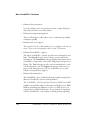
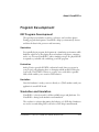
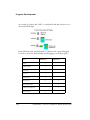
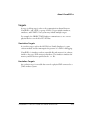
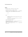
2 ABOUT VISUALDSP++
Figure 2-0.
Table 2-0.
Listing 2-0.
In This Chapter
This chapter contains the following topics:
• “What Is VisualDSP++?” on page 2-2
• “VisualDSP++ Features” on page 2-2
• “Program Development” on page 2-11
• “Code Development Tools” on page 2-22
• “DSP Projects” on page 2-30
• “Tcl Scripting” on page 2-37
VisualDSP++ 2.0 User’s Guide for ADSP-21xxx DSPs
2-1
What Is VisualDSP++?
What Is VisualDSP++?
VisualDSP++ is a tools suite for developing DSP applications and a flexible
management system for DSP projects. It includes:
• Integrated Development and Debugging Environment (IDDE)
with VisualDSP++ Kernel (VDK) integration
• C/C++ optimizing compiler with run-time library
• Assembler, linker, loader, and splitter
• Simulator software with sample programs
VisualDSP++ Features
Integrated Development and Debugging
Environment
The VisualDSP++ single, integrated project management and debugging
environment provides complete graphical control of the edit, build, and
debug process. In this integrated environment, you can move easily between
editing, building, and debugging activities.
Code Development Tools
Depending on the DSP development tools you purchased, VisualDSP++
includes one or more of the following components:
• C/C++ compiler with run-time library
• Assembler, linker, preprocessor, and archiver
• Loader and splitter
2-2
VisualDSP++ 2.0 User’s Guide for ADSP-21xxx DSPs
About VisualDSP++
VisualDSP++ supports ELF/DWARF-2 (Executable Linkable Format)
executable files. VisualDSP++ supports all executable file formats produced by
the linker.
Note: If your system is configured with third-party development tools, you
can select the compiler, assembler, or linker to use for a particular target build.
Source File Editing Features
VisualDSP++ simplifies tasks involving source files. You can easily perform all
the activities necessary to create, view, print, move within, and locate
information.
• Edit text files. Create and modify source files and view listing or
map files generated by the DSP code development tools.
Source files are the C/C++ language or assembly language files that
make up your project.
DSP projects can include additional files such as data files and a
Linker Description File (.LDF), which contains command input for
the linker. For more information about .LDF files, see “Linker
Description Files” on page 2-29.
• Editor windows. VisualDSP++’s Editor is an integrated
code-writing tool, allowing you to focus on code development.
Open multiple Editor windows to view and edit related files, or
open multiple Editor windows for a single file.
• Specify syntax coloring. Configure options that specify the color of
text objects viewed in an Editor window.
This feature enhances the view and helps you to locate portions of
the text, because keywords, quotes, and comments appear in distinct
colors.
• Context-sensitive expression evaluation. Move the mouse pointer
over a variable that is in the scope and view the variable's value.
VisualDSP++ 2.0 User’s Guide for ADSP-21xxx DSPs
2-3
VisualDSP++ Features
• Status icons. View icons that indicate breakpoints, bookmarks, and
the current PC position.
• Editor display format. You can specify an Editor window’s display
format: source mode or mixed mode.
• View offending code. From the Output window’s Build tab,
double-click on an error to jump to the offending code in an Editor
window.
Project Management Features
VisualDSP++ provides flexible project management for the development of
DSP applications, including access to all the activities necessary to create,
define, and build DSP projects.
• Define and manage projects. Identify files that the code
development tools process to build your project. Create this project
definition once, or modify it to meet changing development needs.
• Access and manage code development tools. Configure options to
specify how the DSP code development tools process inputs and
generate outputs.
Tool settings correspond to command-line switches for code
development tools. Define these options once, or modify them to
meet your needs.
• View and respond to project build results. View project status
while a build progresses and, if necessary, halt the build.
Double-click on an error message in the Output window to view the
source file causing the error, or iterate through the error messages.
• Manage source files. From the Project window, you manage source
files and track file dependencies in your project to provide a display
of software file relationships. VisualDSP++ uses code development
tools to process your project and to produce a DSP program.
2-4
VisualDSP++ 2.0 User’s Guide for ADSP-21xxx DSPs
About VisualDSP++
Debugging Features
While debugging your project, you can:
• View and debug mixed C/C++ and assembly code. View C/C++
source code interspersed with assembly code. Line number and
symbol information help you to source-level debug assembly files.
• Run Tcl command-line scripts. VisualDSP++ supports Tool
Command Language (Tcl) version 8.3. Use Tcl and its ADI
extensions to customize key debugging features.
• Use memory expressions. VisualDSP++ permits the use of
expressions that reference memory.
• Use breakpoints to view registers and memory. Quickly add and
remove, and enable and disable breakpoints.
• Set simulated watchpoints. Set watchpoints on stacks, registers,
memory, or symbols to halt program execution.
• Trace program execution history. Trace results show how your
program arrives at a certain point, and show program reads, writes,
and symbolic names.
• Statistically profile the target processor’s PC (JTAG emulator
debug targets only). Random samples are taken and displayed
graphically to indicate where the program uses most of its time.
• Linearly profile the target processor’s PC (Simulation only).
Sample every executed PC and provide an accurate and complete
graphical display of what was executed in your program.
• Create interrupts generated by peripherals. Set up serial port
(SPORT) I/O.
• Transfer data through memory-mapped I/O. Transfer data
without going through peripherals.
VisualDSP++ 2.0 User’s Guide for ADSP-21xxx DSPs
2-5
VisualDSP++ Features
• Create customized register windows. Configure a custom register
window to display a specified set of registers.
• Plot values from DSP memory. Choose from multiple plot styles,
data processing options, and presentation options.
• View pipeline depth of assembly instructions. VisualDSP++
supports the display of the pipeline stage by querying the target
processor or processors through the pipeline interface.
For details, see the VisualDSP++ 2.0 Getting Started Guide for ADSP-21xxx
DSPs.
VDK Features
The VisualDSP++ Kernel (VDK) is a scalable software executive specially
developed for effective operations on Analog Devices’ SHARC DSPs.
Although the kernel is tightly integrated with VisualDSP++, you can also use
it via standard command-line development tools.
The kernel enables you to abstract the details of the hardware implementation
from the software design. As a result, you can concentrate on processing
algorithms.
2-6
VisualDSP++ 2.0 User’s Guide for ADSP-21xxx DSPs
About VisualDSP++
The kernel provides all the basic building blocks required for application
development. Integration of the kernel is characterized as follows:
• Automatic. VisualDSP++ automatically generates source code
framework for each user-requested object in the user-specified
language.
• Deterministic. You can specify a function’s execution time.
• Multitasking. Kernel tasks (threads) are independent of one
another. Each thread has its own stack.
• Modular. The kernel comprises several components. Future releases
will offer additional modules, such as mailboxes, message queues, a
memory manager, and protocol stacks.
• Portable. Most of the kernel components can be written in ANSI
Standard C or C++ and are portable to other Analog Devices DSPs.
• Pre-emptive. The kernel’s priority-based scheduler enables the
highest priority thread not waiting for a signal to be run at any time.
• Prototypical. The kernel and VisualDSP++ create an initial file set
based on a series of template files. The entire application is
prototyped and ready to be tested.
• Reliable. Besides detecting as many errors as possible at build time,
the kernel supports multiple models for error handling.
• Scalable. If a project does not include a kernel feature, the support
code is not included in the target system.
VisualDSP++ 2.0 User’s Guide for ADSP-21xxx DSPs
2-7
New VisualDSP++ Features
New VisualDSP++ Features
VisualDSP++ 2.0 includes the following new features and enhancements:
• No more separate debugging and project management
environments
VisualDSP++ 2.0’s Integrated Development and Debugging
Environment (idde.exe) replaces the Integrated Development
Environment (ide.exe) and Debugger (debugapp.exe) applications
of previous software releases. You no longer have to switch between
the IDE and Debugger applications, because everything is now in a
single user interface.
• Enhanced plotting capability
Plotting provides six plot types and more ways to customize, save,
and restore plot data and presentation settings.
• Linear profiling (Simulator targets only)
Linear profiling is a debug technique that samples the target's PC
register at every instruction cycle. This method of profiling
accurately measures where instructions were executed, since every
PC value is collected. Linear profiling is much slower than statistical
profiling, which is based on random sampling.
• Better Tcl integration
New Tcl commands have been added. The Editor window now
supports Tcl script syntax coloring.
2-8
VisualDSP++ 2.0 User’s Guide for ADSP-21xxx DSPs
About VisualDSP++
• VisualDSP++ Kernel integration
The VisualDSP++ Kernel (VDK) is a software executive between
DSP algorithms, peripherals, and control logic.
The Kernel tab on the Project window provides a tree structure,
which enables you to structure and scale kernel-enabled application
development. Two windows, State History and Target Load,
display VDK information.
Refer to the VisualDSP++ Kernel (VDK) User’s Guide for details.
• Project window enhancements
File icons in the Project window indicate project status (complete
adherence, exclusion, different options).
Files that completely adhere to project settings
Excluded files
Files with options that differ from those defined for the project
• Output window enhancements
The Output window now has two tabs, Console and Build. The
Console tab page displays standard I/O text messages such as file
load status, error messages, and streams. You can also interactively
enter Tcl commands and view Tcl output. The Build tab page
displays Build messages.
VisualDSP++ 2.0 User’s Guide for ADSP-21xxx DSPs
2-9
New VisualDSP++ Features
• Enhanced user preferences
You can configure most user preferences from a single dialog box,
and easily customize your environment.
• Enhanced workspace management
The new Workspace toolbar allows you to switch among namable
workspaces quickly.
• Enhanced user-tool support
The new User-Tools toolbar enables you to configure tools for fast
access. These tools correspond to those on the Tools menu.
• Enhanced VisualDSP++ support
The About VisualDSP++ window provides more information and
links. The General tab page shows software version and license
information. The Components tab page displays information about
VisualDSP++ components, such as the debug target and processor
library. The Tools tab page provides version information for each
code development tool. The Support tab page provides access to
pages on the Analog Devices web site, and enables you to send
e-mail to Analog Devices Support.
• Enhanced documentation
The VisualDSP++ User’s Guide has been thoroughly reorganized to
illustrate VisualDSP++ features and capabilities.
The VisualDSP++ 2.0 Getting Started Guide for ADSP-21xxx DSPs
includes a tutorial that walks you through a real DSP project. While
building and debugging different versions of a DSP project, you
compare their operation efficiencies. You get hands-on experience
with the VisualDSP++ code analysis tools and plotting capability.
2-10
VisualDSP++ 2.0 User’s Guide for ADSP-21xxx DSPs
About VisualDSP++
Program Development
DSP Program Development
The typical project includes simulation, evaluation, and emulation phases.
During program development, VisualDSP++ helps you interactively observe
and alter the data in the processor and in memory.
Simulation
You typically begin program development in a simulation environment while
hardware engineers are developing the new hardware (cell phone, computer,
and so on). You run VisualDSP++ with a simulation target. No physical DSP
is required as you build, edit, and debug your DSP program.
Evaluation
Analog Devices provides EZ-KITs (evaluation boards) that you can use in
your project’s early planning phase to determine which model DSP best fits
your needs. The EZ-KIT connects to your PC via a serial cable or parallel
cable, which enables you to monitor DSP behavior.
Emulation
Once the hardware is ready, you move directly to a JTAG emulator with your
application’s actual DSP board.
Simulation and Emulation
VisualDSP++ is the front end for all the available targets and platforms. Use
VisualDSP++ during both simulation and emulation.
The simulator is software that mimics the behavior of a DSP chip. Simulators
are used to test and debug DSP code before a DSP chip is manufactured.
VisualDSP++ 2.0 User’s Guide for ADSP-21xxx DSPs
2-11
Program Development
An emulator is software that “talks” to a hardware board that contains one or
more actual DSP chips.
In the following table, the check mark () indicates the various debugging
tools that you can use while building and debugging your DSP program.
Tool
Traces
Linear profiles
Interrupts
Streams
Watchpoints
Breakpoints
Emulation
Statistical profiles
Hardware breakpoints
Plot memory
2-12
Simulation
VisualDSP++ 2.0 User’s Guide for ADSP-21xxx DSPs
About VisualDSP++
Targets
A target (or debug target) refers to the communication channel between
VisualDSP++ and a DSP (or group of DSPs). Targets include simulators,
emulators, and EZ-KITs. Your system may include multiple targets.
For example, the SHARC JTAG Emulator communicates to one or more
physical devices over the host PC’s PCI bus.
Simulation Targets
A simulation target, such as the ADSP-21xxx Family Simulator, is a pure
software module and does not require the presence of a DSP for debugging.
VisualDSP++’s simulator reads an executable file and executes it in software,
similar to the way a DSP executes in hardware. The simulator simulates the
memory and I/O devices specified in the .LDF file.
Emulation Targets
An emulation target is a module that controls a physical DSP connected to a
JTAG emulator system.
VisualDSP++ 2.0 User’s Guide for ADSP-21xxx DSPs
2-13
Program Development
Platforms
A platform refers to the configuration of DSPs with which a target
communicates.
Simulation
For simulation, a platform is typically one or more DSPs of the same type. By
default, the platform name is the identical DSP simulator.
Emulation
For emulation, you specify the platform using the JTAG ICE Configurator.
The platform can be any combination of devices. The platform represents the
hardware upon which one or more devices reside. You typically define a
platform for a particular target.
Several platforms may exist for a given debug target. For example, if three
emulators are installed on your system, you might select emulator two as the
platform.
When the debug target is a JTAG emulator, the platforms are the individual
JTAG chains. When the debug target is an EZ-ICE board, the platform is the
board in the system on which you want to focus.
2-14
VisualDSP++ 2.0 User’s Guide for ADSP-21xxx DSPs
About VisualDSP++
Hardware Simulation
VisualDSP++ enables you to simulate a hardware environment when
connected to a simulation target. You can simulate the following:
• Random interrupts that can occur during program execution
• Data transfer through peripherals or memory-mapped I/O
• Depending on the processor hardware, processor booting from a
PROM, host processor, link port, or serial peripheral interface
Setting up VisualDSP++ to generate random interrupts during program
execution enables you to exercise interrupt service routines in your code.
Debugging Overview
Once you have successfully built your DSP project and have generated a DSP
executable file, you can debug the project. Projects developed in VisualDSP++
are run as hardware and software debug sessions.
You can attach to and control the operation of any Analog Devices DSP or
DSP simulator. Download your application code to the processor and use the
debugging facilities in VisualDSP++ to ensure that your application functions
as desired.
VisualDSP++ is your window into the inner workings of the target processor
or simulator. From this user interface, you can:
• Run, step, and halt the program and set breakpoints and
watchpoints
• View the state of the processor’s memory, registers, and stacks
• Perform a trace, cycle-accurate statistical profile, or linear profile
VisualDSP++ 2.0 User’s Guide for ADSP-21xxx DSPs
2-15
Program Development
VisualDSP++ Kernel
A SHARC project can optionally include the VisualDSP++ Kernel (VDK),
which is a software executive between DSP algorithms, peripherals, and
control logic.
The Project window’s Kernel tab accesses a tree control, from which to
structure and scale application development. From this tree control, you can
add, modify, and delete Kernel elements such as thread types, boot threads,
round-robin priorities, semaphores, events, event bits, interrupts, and device
drivers.
Two VDK-specific windows, State History and Target Load, provide views of
VDK information.
Another VDK window, VDK Status, provides thread status data when a
VDK-enabled program is halted.
Refer to the VisualDSP++ Kernel (VDK) User’s Guide for complete details.
2-16
VisualDSP++ 2.0 User’s Guide for ADSP-21xxx DSPs
About VisualDSP++
Program Development Steps
In the VisualDSP++ environment, program development consists of the
following steps:
1. Create a project
2. Configure project options
3. Add and edit project source files
4. Define project build options
5. Build a debug version (executable file) of the project
6. Create a debug session and load the executable
7. Run and debug the program
8. Build a release version of the project
By following these steps, you can build DSP projects consistently and
accurately with minimal project management. This process reduces
development time and lets you concentrate on code development.
These steps, described below, are covered in detail in the online Help and in
the Tutorial chapter of the VisualDSP++ 2.0 Getting Started Guide for
ADSP-21xxx DSPs.
Step 1: Create a Project
All development in VisualDSP++ occurs within a project. The project file
(.DPJ) stores your program’s build information: source files list and
development tools option settings.
VisualDSP++ 2.0 User’s Guide for ADSP-21xxx DSPs
2-17
Program Development
Step 2: Configure Project Options
Define the target processor and set up your project options (or accept default
settings) before adding files to the project. The Project Options dialog box
provides access to project options, which enable the corresponding build tools
to process the project’s files correctly.
Step 3: Add and Edit Project Source Files
A project normally contains one or more C, C++, or assembly language source
files. After you create a project and define its target processor, you add new or
existing files to the project by importing or writing them. Use the
VisualDSP++ Editor to create new files or edit any existing text file.
Adding Files to Your Project
You can add any type of file to the project. The DSP Development Tools
selectively process only recognized file types when building the project.
Creating files to add to your project
You can create new text files. The Editor can read or write text files with
arbitrary names. When you add files to your project, VisualDSP++ updates
the project’s file tree in the Project window.
Editing Files
You can edit the file(s) that you add to the project. To open a file for editing,
double-click on the file icon in the Project window.
The Editor has a standard Windows-style user interface and can handle
normal editing operations and multiple open windows. Additional features
include customizable language- and DSP-specific syntax coloring, and
bookmark capabilities (creation and search).
2-18
VisualDSP++ 2.0 User’s Guide for ADSP-21xxx DSPs
About VisualDSP++
Managing Project Dependencies
Project dependencies control how source files use information in other files,
and consequently determine the build order. VisualDSP++ maintains a
makefile, which stores dependency information for each file in the project.
VisualDSP++ updates dependency information when you change the project’s
build options, when you add a file to the project, or when you choose Update
Dependencies from the Project menu.
Step 4: Define Project Build Options
After you create a project, set the target processor, and add or edit the project’s
source files, you configure your project’s build options. You must specify
options or accept the default options in VisualDSP++ before using the
development tools that create your executable file. You can specify options for
a whole project or for individual files, or you can specify a custom build.
L
VisualDSP++ retains your changes to the build options. Settings
reflect you last changes, not necessarily the original defaults.
Configuration
A project’s configuration setting controls its build. By default, the choices are
Debug or Release.
• Selecting Debug and leaving all other options at their default
settings builds a project that can be debugged. The compiler
generates debug information.
• Selecting Release and leaving all other options at their default
settings builds a project with limited or no debug capabilities.
Release builds are usually optimized for performance. Your test suite
should verify that the Release build operates correctly without
introducing significant bugs.
VisualDSP++ 2.0 User’s Guide for ADSP-21xxx DSPs
2-19
Program Development
You can modify VisualDSP++’s default operation for either configuration by
changing the appropriate entries in the compile, assemble, and link property
pages. You can create custom configurations that include the build options
and source files that you want.
Project-Wide File and Tool Options
Next, you must decide whether to use project-wide option settings or to use
individual file settings.
For projects built entirely within VisualDSP++ with no pre-existing object or
archive (library) files, you typically use project-wide options. New files added
to the project inherit these settings.
Individual File and Tool Options
Occasionally, you may want to specify tool settings for individual files.
Each file is associated with two property pages: a General page, which lets you
choose output directories for intermediate and output files, and a tool-specific
property page (Compile, Assemble, Link, and so on), which lets you choose
options. For information about each tool’s options, see the online Help or the
manual for each tool.
Step 5: Build a Debug Version of the Project
Now you must build a debug version of the project.
Status messages from each code development tool appear in the Output
window as the build progresses.
L
2-20
Note that the output file type must be an executable (.DXE) file to
produce debugger-compatible output.
VisualDSP++ 2.0 User’s Guide for ADSP-21xxx DSPs
About VisualDSP++
Step 6: Create a Debug Session and Load the Executable
After you successfully build an executable file, you set up a debug session. You
run DSP projects that you develop as either hardware or software sessions.
After you specify target and processor information, you must load your
project’s executable file. On the General tab page in the Preferences
dialog box, you can configure VisualDSP++ to load the file automatically
and advance to the main function of your code.
Step 7: Run and Debug the Program
After you successfully create a debug session and build and load your
executable program, you run and debug the program.
If the project is not current (has outdated source files or dependency
information), VisualDSP++ prompts you to build the project before loading
and debugging the executable file.
Step 8: Build a Release Version of the Project
After you finish debugging your application, you build a Release version of
your project to run on the product’s DSP.
VisualDSP++ 2.0 User’s Guide for ADSP-21xxx DSPs
2-21
Code Development Tools
Code Development Tools
Depending on the DSP development tools that you purchased, VisualDSP++
includes one or more of the following components:
• C/C++ compiler with run-time library
• Assembler, linker, preprocessor, and archiver
• Splitter and loader
Note: Available code development tools differ, depending on your DSP. The
options available on the tab pages of the Project Options dialog box enable
you to specify tool preference.
VisualDSP++ supports ELF/DWARF-2 (Executable Linkable Format,
Debugging Information Format) executable files. VisualDSP++ supports all
executable file formats produced by the linker.
Note: If your system is configured with third-party development tools, you
can select the compiler, assembler, linker, splitter, or loader to use for a
particular target build.
2-22
VisualDSP++ 2.0 User’s Guide for ADSP-21xxx DSPs
About VisualDSP++
Compiler
The compiler processes C/C++ programs into assembly code.
The term compiler refers to the compiler utility shipped with the VisualDSP++
software.
The compiler generates a linkable object file by compiling one or more C/C++
source files. The compiler's primary output is a linkable object file with a .DOJ
extension.
You specify the compilation options that you need for your build. Compiler
options are grouped into these categories:
Category
Purpose
General
Optimization, compilation, and termination options
Preprocessor
Macro and directory search options
Warning
Warning and error reporting options
You can access each category of options from the Compile tab page of the
Project Options dialog box.
Note: Compilation options depend on your target DSP and your code
development tools.
For more information, refer to the VisualDSP++ 2.0 C/C++ Compiler and
Library Manual for ADSP-21xxx DSPs.
VisualDSP++ 2.0 User’s Guide for ADSP-21xxx DSPs
2-23
Code Development Tools
Assembler
The assembler generates an object file by assembling source, header, and data
files. The assembler's primary output is an object file with a .DOJ extension.
Assembler terms are defined as follows:
Instruction set — The set of assembly instructions that pertain to a specific
DSP. For information on the instruction set, refer to your DSP’s Hardware
Reference and Instruction Set Reference.
Preprocessor commands — Commands that direct the preprocessor to
include files, perform macro substitutions, and control conditional assembly
Assembler directives — These directives inform the assembler how to process
your source code and set up DSP features. You use directives to structure your
program into logical segments or sections that support the use of a Linker
Description File (.LDF) to construct an image suited to the target system.
For more information, refer to the VisualDSP++ 2.0 Assembler and
Preprocessor Manual for ADSP-21xxx DSPs.
2-24
VisualDSP++ 2.0 User’s Guide for ADSP-21xxx DSPs
About VisualDSP++
Linker
The linker generates an executable program by linking together separately
assembled object files.
The linker's primary output is an executable program file with a .DXE
extension. To make an executable file, the linker processes data from a Linker
Description File (.LDF) and one or more object files (.DOJ).
Linker terms are defined as follows:
Link against — Functionality that enables the linker to resolve symbols to
which multiple executables refer. For instance, shared memory executable files
(.SM) contain sections of code that other processor executables (.DXE) link
against. Through this process, a shared item is available to multiple
executables without being duplicated.
Link objects — Object files (.DOJ) that become linked and other items, such
as executables (.DXE, .SM, .OVL), that are linked against
Linker Description File (.LDF) — Contains the commands, macros, and
expressions that control how the linker arranges you program in memory
Memory — Definitions that provide the linker with a description of your
target DSP system
Overlays — Overlays are swapped in and out of run-time memory, depending
on code operations. The linker produces overlay files (.OVL) that your overlay
manager swaps in and out of memory.
Sections — Declarations that identify the content for each executable that the
linker produces
For more information, refer to the VisualDSP++ 2.0 Linker and Utilities
Manual for ADSP-21xxx DSPs.
VisualDSP++ 2.0 User’s Guide for ADSP-21xxx DSPs
2-25
Code Development Tools
Splitter
The splitter builds boot-loadable files from DSP executables.
Note: This functionality is not available on all DSPs.
The splitter processes a DSP executable file to generate a series of PROM files.
The splitter's primary output is a PROM file with these extensions:
•
.S_#
•
.H_#
•
.STK
Note:
• The splitter is typically used only for programs that execute from
external memory.
• For programs that execute from internal memory, use the loader,
which produces boot-loadable files.
Splitter terms are defined as follows:
Non-bootable PROM-image files — The splitter’s output, which consists of
PROM files that cannot be used to boot-load a system
Splitter — The splitter application, such as elfspl21k.exe, contained in the
software release
2-26
VisualDSP++ 2.0 User’s Guide for ADSP-21xxx DSPs
About VisualDSP++
Loader
The loader builds boot-loadable files from DSP executables. The loader
generates a boot-loadable file by processing one or more DSP executable files.
Use this file to simulate boot-loading.
The loader's primary output is a load file with an .LDR extension. For
ADSP-21xxx DSPs, the boot-loadable file’s extension is .BNM.
Note: The loader is used for programs that execute from internal memory. For
programs that execute from external memory, use the splitter.
Loader terms are defined as follows:
Boot kernel — The executable file that performs the memory initialization on
the target
Boot-loadable file — The loader’s output, which contains the boot loader and
the formatted system configurations. This file is a bootable image file.
Boot-loading or booting — The process of loading the boot loader,
initializing system memory, and starting the application on the target
Loader — The loader refers to the loader application, such as elfloader or
elfspl12, contained in the software release.
VisualDSP++ 2.0 User’s Guide for ADSP-21xxx DSPs
2-27
Code Development Tools
File Associations
VisualDSP++ associates these file extensions as the input to particular DSP
code development tools.
Tool
File Extensions
Compiler
.C, .CPP, and .CXX
Assembler
.ASM, .S, and .DSP
Linker
.LDF, .DLB, and .DOJ
Note:
• VisualDSP++ is case insensitive to file extensions.
• VisualDSP++ supports C++, but VisualDSP does not support C++.
2-28
VisualDSP++ 2.0 User’s Guide for ADSP-21xxx DSPs
About VisualDSP++
Linker Description Files
A Linker Description File (.LDF) describes the target system and maps your
program code with the system memory and processors.
The .LDF file creates an executable file by using:
• The target system memory map
• Defined segments in your source files
The parts of a .LDF File, from the beginning to the end of the file, are
described as follows:
Memory map — The description of the processor’s physical memory, at the
beginning of the .LDF file
SEARCH_DIR, $LIBRARIES,
and $OBJECTS commands — Define the path
names that the linker uses to search and resolve references in the input files
command — Defines the systems’ physical memory and assigns labels
to logical segments within it. These logical segments define program, memory,
and stack memory types.
MEMORY
command — Defines the placement of code in physical memory by
mapping the sections specified in program files to the sections declared in the
MEMORY command. The INPUT_SECTIONS statement specifies the object file
that the linker uses to resolve the mapping.
SECTIONS
For details, refer to the VisualDSP++ 2.0 Linker and Utilities Manual for
ADSP-21xxx DSPs.
VisualDSP++ 2.0 User’s Guide for ADSP-21xxx DSPs
2-29
DSP Projects
DSP Projects
What is a Project?
Your goal is to create a program that runs on a single processor system. All
your development in VisualDSP++ occurs within a project.
The term project refers to the collection of source files and tool configurations
used to create a DSP program. A project file (.DPJ) stores program build
information.
Use the Project window to manage projects from start to finish. Within the
context of a DSP project, you can:
• Specify DSP code development tools
• Specify project-wide and individual-file options for Debug or
Release configurations of project builds
• Create source files
VisualDSP++ facilitates movement among editing, building, and debugging
activities.
VisualDSP++ provides flexibility in how you set up projects. You configure
settings for DSP code development tools and configurations, and specify build
settings for the project and for individual files. You can set up folders that
contain your source files.
Flexibility
VisualDSP++ provides flexibility in how you set up projects. You configure
settings for DSP code development tools and configurations, and specify build
settings for the project and for individual files. You can set up folders that
contain your source files. A project can include VDK support.
2-30
VisualDSP++ 2.0 User’s Guide for ADSP-21xxx DSPs
About VisualDSP++
Project Options
You specify project options, which apply to the entire DSP project. Figure 2-1
shows the top of the Project Options dialog box.
Figure 2-1. Project Options Dialog Box – Top of the Project Tab Page
For each code development tool (compiler, assembler, linker, splitter, and
loader), a tab page presents options that control how each tool processes
inputs and generate outputs. Options correspond to an individual tool’s
command-line switches. You can define these options once or modify them to
meet changing development needs.
Note: You can also access the tools from the operating system command line.
Project options also specify the following information:
• Project target
• Tool chain
• Output file directories
• Post-build options
VisualDSP++ 2.0 User’s Guide for ADSP-21xxx DSPs
2-31
DSP Projects
Project Configurations
By default, a project includes two configurations, Debug and Release,
described in the following table. In previously software releases, the term
configuration was called “build type.”
Configuration
Description
Debug
Builds a project that enables you to use
VisualDSP++ debugging capabilities
Release
Builds a project with optimization enabled
Available configurations appear in the configuration box, which is part of the
Project toolbar, as shown below.
Note: You cannot delete the Release or Debug configuration.
Customized Project Configurations
You can add a configuration to your project. A customized project
configuration can include various project options and build options to help
you develop your project.
2-32
VisualDSP++ 2.0 User’s Guide for ADSP-21xxx DSPs
About VisualDSP++
Project Build
The term build refers to the performance of processing operations (such as
preprocessing, assembling, and linking) on projects and files. During a build,
VisualDSP++ processes project files that have been modified since the
previous build as well as project files that include modified files.
A build differs from a rebuild all. During a rebuild all, VisualDSP++ processes
all the files in the project, regardless of whether they have been modified.
Building a project builds all outdated files in the project and enables you to
make your program. An outdated file is a file that has been modified since the
last time it was built or a file that includes a modified file. For example, if a C
file that has not been modified includes a header file that has been
modified, the C file is out of date.
VisualDSP++ uses dependency information to determine which files, if any,
must be updated during a build.
Note:
• A file with an unrecognized file extension is ignored at build time.
• If an included header file is modified, VisualDSP++ builds the
source files that include (#include) the header file, regardless
whether the source files have been modified since the previous
build.
• File icons in the Project window indicate file status (such as
excluded files or files with specific options that override project
settings).
VisualDSP++ 2.0 User’s Guide for ADSP-21xxx DSPs
2-33
DSP Projects
Build Options
You can specify options for the entire project and for individual files.
Options
Description
Project-wide
Specify options from a tabbed page (for
example, Compile or Link) for each of the
DSP code development tools.
Individual file
These settings override project-wide settings
Custom build step
For maximal flexibility, you can edit the
command line(s) issued to build a particular
file. For example, you might call a third-party
utility.
Post-Build Options
Post-build options are typically DOS commands that execute after a project
has been successfully built. These commands invoke external tools.
For example, you can use a post build-command to copy the final output file
to another location on the hard drive or to invoke an application
automatically.
Automatically copying files and cleaning up intermediate files after a
successful build can be very useful.
2-34
VisualDSP++ 2.0 User’s Guide for ADSP-21xxx DSPs
About VisualDSP++
Project Rules
The Project window displays a project’s files, as shown in Figure-2-2.
Figure 2-2. Project Window – Project Tab Page
The following rules dictate how files and subfolders behave in the Project
window’s file tree.
• You can include any file in a project.
• Only one .LDF file is permitted.
• You cannot add the same file into the same project more than once.
• Only one project (project node) is permitted.
• A file with an unrecognized file extension is ignored at build
time.
• When you add a file to a project, the file is placed in the first
folder configured with the same extension.
• Ιf no such folders are present, an added file goes to the project
level.
VisualDSP++ 2.0 User’s Guide for ADSP-21xxx DSPs
2-35
DSP Projects
Projects Built with VDK
A SHARC project can optionally include the VisualDSP++ kernel (VDK),
which is a software executive between DSP algorithms, peripherals, and
control logic.
The Project window’s Kernel tab accesses a tree control from which you
structure and scale application development. From this tree control, you can
add, modify and delete Kernel elements such as thread types, boot threads,
round-robin priorities, semaphores, events, event bits, interrupts, and device
drivers.
Two VDK-specific windows, State History and Target Load, provide views of
VDK information.
Another VDK window, VDK Status, provides thread status data when a
VDK-enabled program is halted.
Refer to the VisualDSP++ Kernel (VDK) User’s Guide for complete details.
2-36
VisualDSP++ 2.0 User’s Guide for ADSP-21xxx DSPs
About VisualDSP++
Tcl Scripting
VisualDSP++ includes an interpreter for the Tool Command Language (Tcl)
scripting language. This well-documented C-like language, developed by UC
Berkeley researchers, provides an excellent means of scripting repeated
sequences of debugging operations. Use this powerful language to develop
full-blown test applications of DSP systems.
Analog Devices Tcl Commands
Analog Devices has extended Tcl version 8.3 with several procedures to access
key debugging features. Use the power of the Tcl language, coupled with
Analog Devices’ extensions to extensively script your work in VisualDSP++.
VisualDSP++ provides these groups of Tcl commands:
• Target query and manipulation commands
• GUI manipulation commands
• Project build and maintenance commands
Tcl Output
View the output of Tcl commands on the Console tab page in the Output
window.
Tcl output is logged to VisualDSP_log.txt, which, by default, is located in
the directory:
C:\Program Files\Analog Devices\VisualDSP\Data
View this file to analyze Tcl output.
VisualDSP++ 2.0 User’s Guide for ADSP-21xxx DSPs
2-37
Tcl Scripting
Tcl Command Issuance
You can issue a Tcl command from the Console tab page in the Output
window by typing it on Console tab page, as shown in Figure 2-3.
Figure 2-3. Output Window, Console Tab Page – Typing a Tcl Command
Extensive Scripting
For extensive scripting, use the following methods to issue Tcl commands:
• From a command line
To load a script from a DOS command window, type this
command:
idde -f filename
Optionally, add -s and the session name to specify a previously
created session. When no session name is specified, the last session
is used.
Note: If the script encounters an error during execution,
VisualDSP++ automatically exits.
2-38
VisualDSP++ 2.0 User’s Guide for ADSP-21xxx DSPs
About VisualDSP++
• From the Output window
To load a script from the Console tab page in the Output window,
type this command:
source filename
Note: Similar to C/C++, Tcl uses a backslash (\) as its escape
character. When you specify paths in the Windows environment,
you must escape the escape character; for example:
source c:\\my_dir\\my_subdir\\my_file.tcl
Note: You can also use forward slashes to delimit directories in a
path, as in this example:
source c:/my_dir/my_subdir/my_file.tcl
Command execution is deferred until a line is typed without a
trailing backslash. This feature permits the entry of an entire block
of code (or entire Tcl procedures) for the Tcl interpreter to evaluate
at once.
• From a menu
You can quickly issue frequently used Tcl scripts.
From the File menu, choose Recent Tcl Scripts, and then select the
Tcl script.
VisualDSP++ 2.0 User’s Guide for ADSP-21xxx DSPs
2-39
Tcl Scripting
• From an Editor window
In an open Editor window that contains a Tcl script, right-click and
choose Source Tcl Script, as shown in Figure 2-4.
Figure 2-4. Running a Tcl Script from an Editor Window
• From a user-defined tool
From a toolbar, click a user-defined tool, or choose a user-defined
tool from the Tools menu.
2-40
VisualDSP++ 2.0 User’s Guide for ADSP-21xxx DSPs