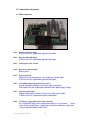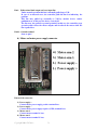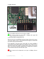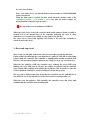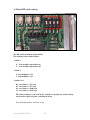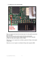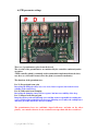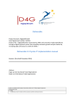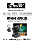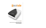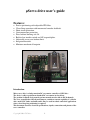
1
µServo drive user’s guide
Features:
Precise positioning with adjustable PID filter.
Closed loop operation with incremental encoder feedback.
Short circuit protection.
Overtemperature protection.
Fixed current limiting at 6.5A.
Built in low inerthia switch and 4X step multiplier.
Adjustable servo error lockout limit.
Integrated heatsink.
Miniature mechanical footprint.
Introduction:
Micro servo drive is a 2nd generation DC servomotor controller of CNCdrive.
The device is able to position one brushed DC servomotor in closed loop.
The position feedback device must be an incremental encoder with A and B channels.
The servo controller has 30Volts and 5Ampers continious current capability, it’s ideal to
drive small CNC lathes and mills and it may be used in robotic and other applications
where closed loop fast positioning is required.
This document describes electrical specifications, signals, connections and pinouts of the
servo controller.
Copyright 2008 CNCdrive.
1
1.) Connections and pinouts
a.) Main connector
Pin1. - Encoder channel A input.
A TTL level (0..5V) signal must applied to this input.
Pin2. - Encoder channel B input.
A TTL level (0..5V) signal must applied to this input.
Pin3. - Vdd output for the encoder.
Pin4. - Encoder ground terminal.
Same as pin 6.
Pin5. - Step signal input.
Motor rotates one increment on every rising edge on this signal.
A TTL level (0..5V) signal must applied to this input.
Pin6. - Grounding input from step/direction source.
Step & dir signals should be referenced to this ground level.
This signal is also the gound input terminal for the digital supply Voltage.
Pin7. - Direction signal input.
Indicates direction of rotation, read on every rising edge on Pin5.
A TTL level (0..5V) signal must applied to this input.
Pin8. - 5V input to supply digital part of the controller.
Use a regulated Voltage source on this input and never exceed values
listed
in the electric specifications – digital part section. Exceeding these values may
cause permament damage in the device!
Copyright 2008 CNCdrive.
2
Pin9. - Bidirectional fault output and reset input line.
Under normal operation this line is internally pulled up to Vdd.
In case of an internal error, the controller pulls this line low indicating the
problem.
This line may pulled up externally to Vdd by another device, switch,
pushbutton etc. in this case the device resets itself.
The line may also pulled to ground potential, in this case the controller stops
operation and releases the motor outputs and freewheels the motor while the
line is pulled low.
Pin10. - Ground terminal.
Same as pin 6.
b.) Motor and motor power supply connector
Pinout of the connector:
1.) Power supply +
Connect motor power supply positive terminal here.
2.) Power supply –
Connect motor power supply negative (GND) terminal here.
3.) Motor arm 1.
Connect motor terminal 1. here.
4.) Motor arm 2.
Connect motor terminal 2. here.
Copyright 2008 CNCdrive.
3
2.) Signs and errors.
There are two LEDs on the board, one green and one red LED.
Under normal operation, the green LED is blinking with around 2Hz
frequency and the red (error LED) is off.
a.) Overcurrent and/or overtemperature error
The device has active current limiting at typicaly 6.5Ampers. If the load is too heavy
on the motor outputs or there’s a short circuit, the motor outputs are tristated and
the controller stops operation automaticly.
If the temperature of the power stage reaches 160°C, the current capability is
reduced and the current limit treshold is lower until the device reaches the 175°C
temperature, then the motor outputs are tristated and the controller stops operation.
There’s a 15°C hysteresis, when the controller detects overtemperature, it cannot be
restarted until the temperature falls under 160°C again.
Both overcurrent and overtemperature error signes are blinking red(error)
LED.
Copyright 2008 CNCdrive.
4
b.) Servo error lockout
Servo error limit can be set with the built in microswitches to 128,512,2048,4096
encoder increments.
When the limit value is reached, in other words when the absolute value of the
commanded position – real position > error limit then the motor outputs are
tristated and the controller stops operation.
The sign of this error is continious red LED on.
When any of the errors occurs, the error line in the main connector (Pin9.) is pulled to
ground level by the internal logic of the controller indicating the error to other
controllers or to external devices which are also connected to this line.
The error can be cleared with appliing Vdd (5Volts) to the error line externally or
switch off and on the device.
3.) Reset and stop circuit
There’s only one pin (pin9. in the main connector) for both reset and stop functions.
Under normal operation this line is an input, but it’s pulled to Vdd with a weak pullup
resistor inside the controller. The controller is running under normal operation when
this line is left unconnected and not pulled to any Voltage levels by any external devices.
When the line pulled to GND, the controller stops working, the Green LED stops
blinking, the error LED stays in off state, the outputs are tristated and the controller
stops working. This condition exist until the line is pulled to Vdd externally or if the line
is released and the controller is restarted with power down and up again.
The error line is bidirectional, that means that the controller can also pull this line to
low (GND) in case of any internal errors, like short circuit, overtemperature, etc.
When the error line pulled to Vdd externally, the controller resets, this clears fault
condition and the controller starts working again.
Copyright 2008 CNCdrive.
5
4.) Micro DIP switch settings.
The DIP switch contains 4 on/off switches.
The meaning of the switches follows:
- Switch 1.
0 - Low inerthia compensation on
1 - Low inerthia compensation off
- Switch 2.
0 - Step multiplier = 1X
1 - Step multiplier = 4X
- Switches 3-4.
00 - error limit = +-128 steps
01 - error limit = +-512 steps
10 - error limit = +-2048 steps
11 - error limit = +-8192 steps
The switch settings are only read by the controller at startup, new switch settings
sensed and accepted only after restarting the device.
Note: Switch positions: 0= down, 1=up.
Copyright 2008 CNCdrive.
6
5.) Analog servo error measurement
There’s a testpoint on the board with an analog output, the analog signal is proportional
to the servo error.
Place an oscilloscope probe onto the testpoint and to the ground potential.
When the servoerror is 0 increments, in other words the rotor is in the commanded
position, the voltage on the testpoint is 2.5VDC (VDD/2).
When the servo error is equal to the error limit(see point4.), the Voltage on the testpoint
is Vdd (5VDC).
When the servo error is equal to -error limit, the Voltage on the testpoint is 0VDC.
Copyright 2008 CNCdrive.
7
6.) PID parameter settings
There are 3 potentiometers placed onto the board.
The set value of the potentiometers are monitored by the controller continiously under
operation.
A PID controller which is commonly used in automatition implemented into the drive,
user have to set P,I and D terms to fit to the plant (servomotor+mechanics).
The functions of the potentiometers:
Pot. P.) Proportional term, gain
Increasing the PID gain causes less servo error, faster response, but it also decrease
stability of the control loop.
Pot. D.) Differential term, damping
Increasing the damping causes slower response, but increases stability of the loop.
Pot. I.) Integral term, integral gain
Integral gain is to trim out following error and this term is responsible for settling into
correct position. Increasing this gain decreases following error, makes the settling faster
and more precisible, but it also decrease stability.
The potentiometers have two end-limits (signed with max. and min. on the above
picture), care must be taken to do not overturn/overtorque them with the screwdriver!
Copyright 2008 CNCdrive.
8
7.) Step and direction interface
Step(Pin5.) and direction(pin6.) input pins found in the main connector.
When a rising edge occurs on the step pin, the controller rotates the motor one
increment to CW or CCW, the direction of rotation depends on the state of the direction
pin.
The inputs are not isolated from the digital power supply, the signals are on the digital
PSU’s potential, it is recommended to opto isolate the signal when connected to the
computer.
Alternatively the 5V for the logic part can be the PC’s 5V supply e.g. from the USB port,
this is safe, because the power bridge of the controller is isolated from the logic part.
8.) Incremental encoder interface
The controler loop is closed in position. An incremental encoder
which is tipically connected onto the motor’s backshaft provides the
position feedback for the controller. The encoder must be an
incremental type with at least A and B channels. Some encoders have
Index channel, but the controller does not use this channel, there’s
no need for the Index channel to use the encoder with the uservo
controller. The encoder must have TTL level outputs on the A and B
channels otherwise Voltage level translation is nessessary.
9.) Current limiting
Continious current flow is limited by the drive at tipically 5Ampers and peak-current is
limited at tipicaly 6.5Ampers. When motor current rises above 6.5A, the outputs turned
of for a short time, while current falls under 5A.
If the load is too heavy on the outputs or there’s a short circuit, the drive will be unable
to limit the current and the current will rise above 10A, in this case automatic shutdown
occurs to protect the drive against overcurrent, the outputs are tristated and the
controller stops working. Fault condition can be cleared in the way written in point 2.a.
of this documentation.
Copyright 2008 CNCdrive.
9
10.) Optional end/limit swithes.
There’s an option to connect two safety limit switches to the controller.
The factory programming terminal has two pins(pin 1. and 2.), which are inputs and
used to disable the running of the controller to one-one direction.
A default open type switch can be connected onto the pins, when the machine runs onto
the limitswitch, it should pull the line low. In this case one direction of rotation is
disabled and the motor is freeweeled to that direction.
The two switches are for disable the two directions independently, so 1-1 limit switch
can be placed separately wired onto the machine’s axis.
When the machine runs onto the limit switch, only one direction is disabled, therefor the
axis can be moved down from the switch with step and direction signals that commands
the machine to the oposite direction.
It is important to use the correct input for the correct direction and do not exchange the
pins for the directions, otherwise they will not work as they have to.
Never apply any Voltage to the other 2 pins in this pin connector, those pins are used for
factory programming of the device. Appliing Voltage to those pins may cause
permament damage to the device.
Copyright 2008 CNCdrive.
10
11.) Important notices, what can damage the device!
Exceeding digital supply maximum allowed Voltage.
Exceeding motor supply maximum allowed Voltage.
Reverse polarity connection on digital supply connector.
Reverse polarity connection on power supply connector.
Overvoltage on encoder channels or on any digital pins.
Always take care and check these connections for the correct Voltage
levels and polarity before applying Voltage to the device.
12.) Troubleshooting (FAQ)
Q: When I power up the controller and try to rotate the shaft of the
motor, the motor jumps out of position and do not stop for a while,
after some rotations it stops with error. (Red LED on.)
A: The encoder A & B channels connected backwards and the
controller moves the motors in wrong direction. Exchange A and B
channel wire connections of the encoder in the main connector.
Q: I have an absolut encoder attached to my motor can I use it?
A: No, the encoder must be an incremental type with at least A and B
quadrate channels and must have TTL level signals. Resolvers with
sin/cos signals will also not work.
Q: What CNC controller software should I use?
A: Any controller software with step and direction signals will work.
Q: I have a big motor, which has higher current and voltage rating
then the drive, can I use it?
A: Yes, but the motor supply must be equal or lower than 30VDC, the
current will be limited automaticly at 6.5Amps, so you may get lower
torque than the rated of your motor.
Q: I like to drive the device with a PLC, is it possible and if yes, how?
A: PLCs often have 24V outputs and the servo controller accepts TTL
level (0..5V) signals. You must use a resistor-zener diode clamping
circuit externally on the outputs of the PLC to translate the 24V
outputs to TTL (0..5V) Voltage level.
Copyright 2008 CNCdrive.
11
13.) Electric specifications:
Digital supply
Digital Supply Voltage
Digital Supply Current
Symbol
Vdd
Idd
Min
4.5
80
Typ
5
100
Max
5.5
140
Unit
V
mA
Motor Supply
Symbol
Min
Typ
Max
Unit
Motor Supply Voltage
Vm
8
28
V
Range
Continious current
Icm
5
5
5
A
capability
Peak current capability
Ipm
6.5
7
8.5
A
Overcurrent detection* level
Iov
9
10
11
A
*Overcurrent shutdown occurs when drive is unable to regulate the current under the
overcurrent detection level for more than 100usec, this may happen under too heavy load or in
short circuit on the motor output pins.
Termal management
Symbol
Min
Typ
Max
Unit
Termal shutdown*
Ts
170
175
175
°C
Termal hysteresis before
Th
-15
-15
-15
°C
new powerup enabled
*Measured in the power switching element’s core.
The cooling rib surface feels hot above 60°C for bare human hand, avoid touching it when
the device is under operation. This temperature is measured in the switching elements’ core,
the cooling-rib’s temperature can be lower than the listed values at overtemperature
shutdown.
Incremental Encoder
Symbol
Min
Typ
Max
Unit
Encoder Supply Voltage
Ve
Vdd-0.6
Vdd
Vdd+0.6
V
Encoder Channels’ Volage*
Vech
Vdd-0.6
Vdd
Vdd+0.6
V
Encoder frequency max.**
1
1
1
MHz
*Encoder must be a TTL level type with single ended A and B channel quadrate outputs.
**Digital filers protects encoder lines from noise and fault triggering, the filter works upto
1Mhz frequency.
Copyright 2008 CNCdrive.
12
Step and direction interface
Symbol
Min
Typ
Max
Unit
Step signal minimum pulse
Tc
1
infinity
usec
width.
Direction signal minimal
Tdv
1
infinity
usec
allowed valid time after step
pulse rising edge.*
Step signal frequency
0
300
kHz
*Direction signal must be on valid voltage level after the rising edge of the step signal for at
least 1usec.
Mechanical dimensions:
Width: 60mm (app. 2.4 inch)
Length: 45mm (app. 1.8 inch)
Height: 16mm (app. 0.63 inch)
Copyright 2008 CNCdrive.
13
Safety notes:
-This device is used to control machines’ movements. Moving
machines and moving objects/parts in machines can be
hazardous, always take care when operating these devices.
-Always wear safety glowes and glasses when using the
devices and/or your automatic machines.
-Always use isolation transformers to supply the devices!
-Avoid touching the cooling rib of the controller, it can get
hot under operation and may cause injury when touching.
The device is protected by international Chipset, Schematics and Firmware
Patents, copying the device in any form is forbidden!
This documentation may contains errors and may be unclomplete, please
ask our support in case of any questions or if you explored any errors in
this document and like to help our work.
To make any modifications in this documentation by anybody else than the
author (CNCdrive) is forbidden in any form.
More informations at: http://www.cncdrive.com
Copyright 2008 CNCdrive.
14