1
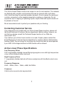
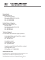
ALP5 BIAMPLIFIED DIRECT
FIELD MONITOR SYSTEM
USER GUIDE
Thank you for choosing the Active Linear Phase™ Biamplified Direct Field Monitor
System. To get the most from your new monitors, please take a moment to read this
manual and familiarize yourself with the product’s features, set-up, and use.
About the Active Linear Phase Monitor System
Our engineers have spent years designing transducers, studio electronics, and
high performance studio monitoring systems—including some of the most popular
professional speakers used today. Now, using the latest digital acoustic design tools
and high performance driver and power amplifier technology, they’ve developed the
Active Linear Phase 5, the new standard for performance and value in biamplified
direct field monitors.
The Active Linear Phase 5 features the time-proven mineral-impregnated 5.25” low
frequency driver that’s been at the heart of “small footprint” Event monitor systems
from the start, including the Tria™, the Project Studio 5™, and most recently, the
Tuned Reference 5™. The unit’s high frequency driver is a direct descendant
of the one used in the critically acclaimed Studio Precision series. But the real
magic comes in the sonic combination of these two custom-designed components,
courtesy of the ALP5 front panel baffle. The seemingly simply baffle is actually a
rather cleverly engineered design that creates an elliptical wave guide for the high
frequency driver while at the same time aligning the phase and time relationships of
the low and high frequency driver components. The result is a monitor that provides
significantly greater imaging accuracy and a wider sweet spot than those using
traditional designs.
Unpacking
The shipping container and inner box are designed to protect your speakers during
transit. Please unpack and check your speakers carefully, and immediately report
any damage to your dealer or to the company that delivered the speakers to you.
The packing materials are designed to be reused—do not discard them. If you need
to return the speakers to the factory for repair, they must be shipped in the original
packaging.
Setup
You’ll notice that the Active Linear Phase monitors are physically identical.
When used in a stereo configuration, there is no physical or acoustic distinction
between the left and right speakers. Note, too, that the cabinets can sit vertically or
horizontally without regard for performance, so long as both cabinets are situated in
the same direction. When placing them in a horizontal position, orient the cabinets
with the high frequency drivers pointing to the outside, away from each other. Since
each cabinet’s bass port is front-mounted, you can position the monitors near a wall
(or even in a wall) without fear of blocking the port, which would compromise the
bass response.
Your monitors should be placed on a stable surface at about ear level. A typical
location would be slightly behind and to either side of a small console. The distance
between the monitors should equal the distance from the listener to either speaker.
This is the common “equal length triangle” rule for speaker placement shown in
Figure 1.
Figure 1. When the listener and the monitors are positioned in an
equal triangle with the monitors directly facing the listener, the listener is
situated in the “sweet spot,” which yields optimum stereo reproduction.
Notice that Figure 1 also shows the speaker cabinets turned slightly inward, so
that the driver components directly face the listening position. When oriented
this way, the listener is in the “sweet spot,” which yields the most accurate stereo
reproduction. When the speakers are properly rotated toward you, the ALP5’s power
indicator LED will be clearly visible, with no part of it blocked by the front panel
baffle. If you must mount the speakers substantially above or below ear level, you
will also need to tilt the cabinets downward or upward to keep the driver components
directly facing you. Again, use the LED as an indicator of proper positioning.
As you become more familiar with your speakers, you may find it helpful to move
around in the soundfield to locate the optimum listening position for your particular
monitoring environment. But if you follow the equal distance, ear-level, face-on rules
outlined above, you’ve already optimized their position for a single user in most
situations.
Connections and Operation
Please refer to Figure 2 on the opposite page.
Balanced XLR Line Input This jack accepts a male XLR connector, wired for either
balanced or unbalanced operation. For balanced operation, please consult the pin
wiring diagram on Page 5 or on the monitor’s back panel.
The Line 1 input is hardwired in parallel with the Line 2 input, so either may be used
as an input or as a pass-through connection. Input specifications apply to both inputs
equally.
Balanced 1/4” Line Input This jack accepts a male two-conductor 1/4” TS or threeconductor 1/4” TRS connector, wired for either balanced or unbalanced operation.
For unbalanced operation with a TS connector, the minus signal is automatically
grounded; with a TRS connector you have the option of leaving the minus input
open or grounded. We recommend, however, that you ground the minus input. For
balanced operation, which requires using a TRS connector, please consult the pin
wiring diagram on Page 5 or on the monitor’s back panel.
The Line 2 input connector is hardwired in parallel with the Line 1 input connector, so
either may be used as an input or as a pass-through connection. Input specifications
apply equally to both inputs.
Unbalanced RCA Line Input This jack accepts a male RCA connector, wired for
unbalanced operation. This jack is hardwired in parallel with the balanced line inputs.
However, due to it being an unbalanced input, we do not recommended using it in
combination with either of the balanced inputs, as this will unbalance those inputs,
possibly causing degradation of the audio signal.
Voltage Selector. The correct voltage will have already been set for your region
so there is no reason to touch this selector. Only authorized Event technicians are
permitted to change the voltage. Please note that any evidence of tampering with
the voltage selector will invalidate the products warranty.
On/Standby
INPUT
SENSITIVITY
-5dB
Input Sensitivity
-20dB
MAX
Balanced XLR
Line Input
BALANCED
INPUTS
Balanced 1/4” TRS Line Input
Tip - single (-)
Ring - single (+)
Sleeve - ground
Pin 3 (+)
UNBALANCED
INPUT
Pin 2 (-)
Pin 1 (ground)
Unbalanced RCA Line Input
ALP5 BIAMPLIFIED DIRECT
F I E L D M O N I TO R S Y S T E M
WWW.EVENT1.COM
CAUTION
VORSICHT
BEFORE OPENING
PULL MAIN PLUG
VOR DEM OFFNEN
NETZSTECKER ZIEHEN
AVERTISSEMENT
POUR PREVENIR LES RISQUES D’INCENDE OU DE CHOC
ELECTRIQUE, EVITER D’EXPOSER CET APPAREIL A LA
Voltage Selector
WARRANTY
VOID
IF REMOVED
FUSE INSIDE INLET T4AL 250V
WARNING: TO REDUCE THE RISK OF FIRE OR
ELECTRIC SHOCK, DO NOT EXPOSE THIS APPLIANCE
TO RAIN OR MOISTURE.
Power Connector
■ 100V ~
■ 120V ~
■ 220V ~
■ 240V ~
50/60Hz
60Hz
50Hz
50/60Hz
40VA
40VA
40VA
40VA
Figure 2. Active Linear Phase rear panel connections and controls.
Input Sensitivity This control is used to compensate for different signal levels that
appear at the input. The control has a 20dB range; when set at maximum (MAX),
0.5V RMS input at the balanced in or 0.25V RMS at the unbalanced in will produce
full amplifier output. Note that when the signal appearing at the input is too hot, the
amplifiers may overload, causing distortion. If this occurs, attenuate (decrease) the
Input Sensitivity by turning the control counter-clockwise.
Standby Switch Push to turn the amplifiers ON; push again to activate standby
mode. When the amplifiers are ON, the green LED located on the front of the
monitor will illuminate. Note: In standby mode the mains power is still on.
Power Connector This connector accepts the detachable AC line cord. Use the
line cord supplied with your monitor, and make sure it is fully seated into the Power
Inlet connector. For safety reasons, do not attempt to defeat the line cord’s ground
connection. The power connector also houses the mains fuse which is replaceable
by the user.
Care and Maintenance
Your Active Linear Phase monitors are simple to care for and maintain. The cabinets
are finished with a durable vinyl laminate that can be cleaned with a soft damp
cloth. Avoid touching the exposed speaker elements. Do not expose the rear panel
controls, connectors, or the speaker elements to moisture or chemicals. Do not
expose the unit to dripping or splashing liquids; objects filled with liquids should not
be placed on the unit.
Mix at reasonable levels to protect your speakers and your hearing.
Contacting Customer Service
If you experience any trouble with your Active Linear Phase monitors, please call
the Event Electronics Customer Service department. Before calling, however, we
ask that you please consult the Technical Support section of our Web site, www.event1.com.
If you believe your Active Linear monitor is in need of repair, please contact the
Event Electronics Customer Service department to request a Return Authorization
Number (RA#). We can accept for servicing only those units that are accompanied
by an RA#. Units shipped without an RA# number will be refused.
Active Linear Phase Specifications
Low Frequency Driver
5.25” magnetically shielded mineral-filled polypropylene cone with high temperature
voice coil and damped rubber surround.
High Frequency Driver
1” magnetically shielded natural soft dome neodymium with ferrofluid-cooled voice
coil.
Frequency Response
45Hz – 39kHz; 53Hz – 19kHz, ±3dB, Ref 500Hz.
Crossover
2.6kHz active second-order asymmetrical
Studio Precision Specifications (cont.)
Sound Pressure Level (Output)
>105dB
Noise
>100dB below full output, 20kHz bandwidth, unweighted
Input Connectors
XLR and 1/4” connectors; accept balanced or unbalanced sources RCA connector;
accepts unbalanced sources
Polarity
Positive signal at + input produces outward low frequency cone displacement
Input Impedance
40kΩ balanced, 20kΩ unbalanced
Input Sensitivity
0.5V RMS input at the balanced ins or 0.25V RMS input at the unbalanced in
produces full output with Input Sensitivity control at maximum.
Input Sensitivity control range
20dB
Protection
RF interference, output current limiting, over temperature, turn-on/off transient,
subsonic filter, internal mains fuse.
Indicators
Power ON LED indicator.
Power Requirements
40VA, factory programmed for either 100V~ 50-60Hz, 120V~ 60Hz, 220~ 50Hz,
240V~ 50Hz mains.
Cabinet
5/8” vinyl-laminated MDF, internally insulated.
Dimensions
7.5” W x 10.5” H x 9” D
Weight
11.95 lds each.
Specifications subject to change without notice.
International:
RØDE Microphones.
107 Carnarvon Street
Silverwater NSW 2128 Australia
Ph: 61 2 9648 5855
Fax:61 2 9648 2455
United States of America:
©2003 Event Electronics, LLC
P.O. Box 4189
Santa Barbara, CA 93140-4189
Ph: 805 566 7777
Fax:805 566 0071
Technical Support:
For information and technical support questions.
In the United States and Puerto Rico, contact:
[email protected]
Ph: 805 566 7777
In Australia, contact:
[email protected]
Ph: (02) 9648 5855
Anywhere except USA and Puerto Rico, contact:
[email protected]
Ph. Australia:+61 2 9648 5855
www.event1.com
Event Electronics® is a registered trademark of Event Electronics, LLC.
Studio Precision is a trademark of Event Electronics, LLC.
Rode Microphones is a division of Freedman Electronics Pty Ltd.