1
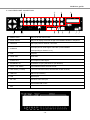
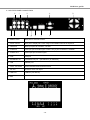
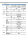
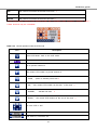
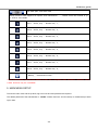
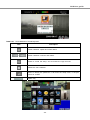
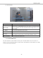
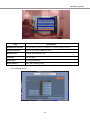
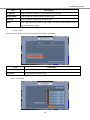
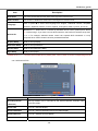
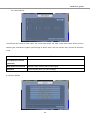
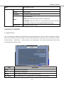
DVR User guide USER GUIDE H.264 Digital Video Recorder V1.0 This document contains preliminary information and subject to change without notice DVR User guide SAFETY PRECAUTIONS WARNING TO REDUCE THE RISK OF FIRE OR ELECTRIC SHOCK, DO NOT EXPOSE THIS APPLIANCE TO RAIN OR MOISTURE. NOTE: This equipment has been tested and found to comply with the limits for a class digital device, pursuant to part 15 of the FCC Rules. This symbol is intended to alert the user to the presence of unprotected “Dangerous voltage" within the product's enclosure These limits are designed to provide reasonable protection against harmful interference when the equipment is operated in a commercial that may be strong enough to environment. This equipment generates, uses, cause a risk of electric shock. and can radiate radio frequency energy and, if not installed and used in accordance with the This symbol is intended to alert the user to the presence of instruction manual, may cause harmful interference to radio communications. Operation important operating and of this equipment in a residential area is likely to maintenance (servicing) cause harmful interference in which case the user instructions in the literature accompanying the appliance. will be required to correct the interference at his own expense. -2- DVR User guide SAFETY WARNING AND CAUTION The following are the statements of warning and caution. Please read completely for safe usage of the Device ☞ If you don’t read these warning and Caution carefully, You may be injured or cause property loss. Warning Turn off the system before installing the system. Do not place any liquid container on the system, Do not plug in several electric devices to the same such as water, coffee, or beverage. outlet. If liquid is poured onto the system, it can cause a This may cause heating, fire, or electric shock. system breakdown or cause fire. Prevent power cable from being severely bent or Clean the dust around the system on regular basis. pressed by a heavy object. When cleaning the system, always use dry cloth. This may cause fire. Do not use wet cloth or other organic solvents. This may damage the surface of the system and can cause system breakdown or electric shock. Avoid any place with moisture, dust, or soot. When pulling the power cable from the plug, do so This can cause fire or electric shock. gently. Do not touch the plug with wet hands and avoid using the plug if the holes on the outlet are too loose. This may cause fire or electric shock. Don’t attempt to disassemble, repair, or modify the Install the system in a cool place without direct system on your own. It is extremely dangerous due sunlight and always maintain room temperature. to high voltage running through the system. Avoid candle light and heat-generating devices This may cause fire, electric shock, or serious such as heater. Keep the system away from places injuries. where many people pass. This many cause fire. -3- DVR User guide Check for any danger signs such as moist floor, Install the system on a plain surface with sufficient loosened or damaged power cable, or unstable air ventilation. Do you place the system on elevated surface. If you encounter any problems, ask for surface. assistance from your dealer. This may cause system breakdown or serious This may cause fire or electric shock. injuries. Keep at least 15cm between the back of the system The power outlet must be placed on a ground, and and a wall for the cables connected into the the voltage range must be within 10% of the voltage system. Otherwise, cables may be bent, damaged, rate. Do not use the same outlet with a hair dryer, or cut. iron, refrigerator, or any heating appliances. This may cause fire, electric shock, or injuries. This may cause fire, heating, an electric shock. When the system’s battery is deplete, you must The manufacturer is not responsible for deleted change it with the same or equivalent type of battery data caused by user’s mishandling. specified by the manufacturer. Depleted batteries should be discarded according to manufacturer’s instructions. This may cause an explosion. <Location of Battery> Please separate a battery as above image -4- DVR User guide Caution Do not install the system in a place with high Install the system in a place with appropriate moisture magnetic, electric wave, or wireless devices such and temperature level. as radio or TV. Avoid installing the system with high (over 40°C) or Install the system in a place without magnetic low (under -5°C) temperature. objects, electric frequencies, or vibration. Prevent any substances from being inserted into Do not place any heavy object on the system. the system. This may cause system breakdown. This may cause system breakdown. Install the system in a place with sufficient air Install the system on a stable and leveled surface. ventilation. The system may not operate properly. Keep at least 15cm distance between the back of the system and a wall and at least 5cm distance between the side of the system and a wall. The system can be damaged from a strong impact The outlet must be placed on the ground. or vibration. Avoid throwing objects within the vicinity of the system. Avoid direct sunlight or any heating appliances. If there is strange sound or smell, unplug the power cable immediately and contact the service center. This may cause fire or electric shock. Ventilate the air inside the system operation room . In order to maintain stable system performance, have and tighten the system cover firmly. your system checked regularly by the service center. System breakdown may be cause by inappropriate The manufacturer is not held responsible for system environment. breakdown caused by user’s mishandling. It is recommended to use AVR (Automatic Voltage Regulator) for stable power supply. It is recommended to coil the core-ferrite around the connector of the system to avoid electromagnetic interference. -5- DVR User guide Table of Contents 1. PACKING LIST............................................................................................................... 8 2. PANEL LOCATION........................................................................................................ 9 2-1 FRONT PANEL CONTROLS .............................................................................................................................................9 2-2 16CH REAR PANEL CONNECTORS..............................................................................................................................10 2-3 8CH REAR PANEL CONNECTORS................................................................................................................................11 2-4 4CH REAR PANEL CONNECTORS................................................................................................................................12 3. Product Specification .................................................................................................... 13 4. LIVE, PLAYBACK AND PTZ OPERATIONS.......................................................... 14 4-1 LIVE Mode ........................................................................................................................................................................14 4-2 PLAYBACK Mode ............................................................................................................................................................18 4-3 PTZ Mode ..........................................................................................................................................................................20 5. MAIN MENU SETUP................................................................................................... 22 5-1 RECORD SETUP ..............................................................................................................................................................24 5-1.1 Quality & Frame Rate Setup .......................................................................................................................................25 5-2 EVENT SETUP .................................................................................................................................................................25 5-2.1 MOTION SETUP .......................................................................................................................................................26 5-2.2 SENSOR SETUP ........................................................................................................................................................27 5-3 SCHEDULE SETUP..........................................................................................................................................................28 5-3.1 Schedule Record Setup ...............................................................................................................................................29 5-3.2 Holiday Setup..............................................................................................................................................................29 5-4 CAMERA SETUP..............................................................................................................................................................30 5-5 ACCOUNT SETUP ...........................................................................................................................................................30 5-5.1 Permission Setup.........................................................................................................................................................31 5-5.2 User Picture Setup.....................................................................................................................................................32 5-6 NETWORKING SETUP ..................................................................................................................................................32 5-6.1 NETWORKING SETUP ............................................................................................................................................33 5-6.2 HTTP Setup..............................................................................................................................................................34 5-6.3 DDNS Setup.............................................................................................................................................................35 5-6.4 Mail Setup ................................................................................................................................................................36 5-7 PTZ & RS485 SETUP .......................................................................................................................................................36 -6- DVR User guide 5-8 SYSTEM SETUP...............................................................................................................................................................37 5-8.1 DISPLAY SETUP .......................................................................................................................................................38 5-8.2 DATE/TIME SETUP ..................................................................................................................................................39 5-8.3 BUZZER & RELAY SETUP ......................................................................................................................................41 5-8.4 SPOT SETUP..............................................................................................................................................................42 5-9 UTILITY SETUP...............................................................................................................................................................42 5-10 DIAGNOSTIC .................................................................................................................................................................43 6 BACKUP & SEARCH ................................................................................................... 44 6-1 BACKUP SETUP ..............................................................................................................................................................44 6-2 SEARCH SETUP...............................................................................................................................................................45 6-2.1 EVENT SEARCH.....................................................................................................................................................45 6-2.2 TIME SEARCH ........................................................................................................................................................47 6-3 How to search via Web monitoring or Program .................................................................................................................48 6-3.1 Web Monitoring. .........................................................................................................................................................49 6-3.2 Client Program ............................................................................................................................................................49 6-4 Client Program Operation ..................................................................................................................................................50 7. MOBILE APPLICATION INSTALLATION AND USAGE .................................... 52 7-1 Mobile Application Installation and Operation for Symbian System.................................................................................52 7-1.1 Mobile Application Installation...................................................................................................................................53 7-1.2 Mobile Application Operation.....................................................................................................................................53 7-1.3 Live Monitoring Operation .........................................................................................................................................55 7-2 Mobile Application Installation and Operation for Windows Mobile System ...................................................................57 7-2.1 Mobile Application Installation...................................................................................................................................57 7-2.2 Mobile Application Operation.....................................................................................................................................58 7-2.3 Operation under the LIVE monitoring. .......................................................................................................................59 7-3 The Supported Mobile OS List ..........................................................................................................................................61 8. Backup Viewer ............................................................................................................... 61 APPENDIX DDNS Account Registration..................................................................... 62 -7- DVR User guide 1. PACKING LIST DVR SET SOFTWARE CD REMOTE CONTROLLER BATTERY MANUAL SCREWS SATA HDD CABLE HDD Bracket (For 16CH DVR ) Sponge Ring & Screws (For 4CH & 8CH DVR) POWER CABLE & Adaptor SATA Power Cable -8- DVR User guide 2. PANEL LOCATION 2-1 FRONT PANEL CONTROLS 2 ○ 1 ○ 12 ○ 13 ○ 6 ○ 8 ○ 7 ○ Control Keys 4 ○ 3 ○ 2 BACKUP ○ In LIVE mode, press to display the BACKUP menu. 3 PTZ ○ In LIVE mode, press to display the PTZ menu. 4 MENU ○ In LIVE mode, press to display menu. 5 ESC ○ In SETUP mode, press to return to previous page.. ⑥SEARCH In LIVE mode, press to Display the search menu. 7 ○ REW In PLAYBACK mode, press to play rewind. 8 ○ STOP In PLAYBACK mode, press to stop playing back. 9 ○ FF In PLAYBACK mode press to play forwards. 10 REC ○ Start or stop recording.. 11 PLAY / PAUSE ○ In SEARCH mode, press to play or pause playback. 12 LED DISPLAY ○ NETWORK: the status of Network connection 13 USB PORT ○ USB Port (For Backup Device) / / / 11 ○ 15 ○ 14 ○ Description In LIVE mode, It locked all accounts. ⑮ 10 ○ 9 ○ 1 LOCK ○ 14 SEL MODE ○ 5 ○ HDD: Hard disk is in use. In SETUP mode, press to enter values. In PLAYBACK mode, switch between full, quad, 9channel, 16-channel display in order. Press to move cursor up, down, right, left. -9- DVR User guide 2-2 16CH REAR PANEL CONNECTORS 1 ○ 9 ○ 2 ○ ⑮ 4 ○ 6 ○ ③ 10 ○ 7 ○ 11 ○ 12 ○ 8 ○ 5 ○ ⑭ ⑬ 1 MAIN monitor ○ BNC port for the main monitor. 2 SPOT monitor ○ BNC port to display full screen image of all installed cameras in sequence. 3 VIDEO IN ○ BNC input ports for cameras, 16 in total. RCA input port for audio signal. There are 4 ports available. 4 AUDIO IN ○ (corresponding to channel 1 to 4) 5 VGA ○ VGA port. 6 LOOF OUT ○ LOOF OUT 7 AUDIO OUT ○ RCA output for audio signal. 8 EXTERNAL I/O ○ EXTERNAL I/O port (see below for pin definition) 9 NTSC/PAL Switch ○ Switch between NTSC and PAL format. 10 75Ω Switch (1~16CH) ○ If you use Loof Out function, Set Switches of each channel, 11 USB Port ○ USB Port (For Mouse) 12 LAN ○ Network port. ⑬ DC 12V Socket for a DC 12V input ⑭ Power Switch Switch Power ON or OFF ⑮ FAN . -10- DVR User guide 2-3 8CH REAR PANEL CONNECTORS 2 ○ 9 ○ 10 ○ 1 ○ 4 ○ ⑪ 5 ○ ③ 8 ○ 6 ○ 7 ○ 1 MAIN monitor ○ BNC port for the main monitor. 2 SPOT monitor ○ BNC port to display full screen image of all installed cameras in sequence. 3 VIDEO IN ○ BNC input ports for cameras, 8 in total. 4 AUDIO IN ○ RCA input port for audio signal. There are 4 ports available. (corresponding to channel 1 to 4) 5 AUDIO OUT ○ RCA output port for audio signal. 6 VGA ○ VGA port 7 EXTERNAL I/O ○ EXTERNAL I/O port (see below for pin definition) 8 LAN ○ Network port 9 DC 12V ○ Socket for a DC 12V input. ⑩ USB Port USB Port (For Mouse) ⑪ FAN -11- DVR User guide 2-4 4CH REAR PANEL CONNECTORS 2 ○ ⑩ ③ 1 ○ 11 ○ 4 ○ 5 ○ 9 ○ 8 ○ ⑫ 6 ○ 7 ○ 1 MAIN monitor ○ BNC port for the main monitor. 2 SPOT monitor ○ BNC port to display full screen image of all installed cameras in sequence. 3 VIDEO IN ○ BNC input ports for cameras, 4 in total. 4 AUDIO IN ○ RCA input port for audio signal. There is only a port of Channel 1 available. 5 AUDIO OUT ○ RCA output port for audio signal. 6 VGA ○ VGA port 7 EXTERNAL I/O ○ EXTERNAL I/O port (see below for pin definition) 8 LAN ○ Network port 9 NTSC/PAL Switch ○ Switch between NTSC and PAL format. ⑩ DC 12V Socket for a DC 12V input. 11 USB Port ○ USB Port (For Mouse) ⑫ FAN -12- DVR User guide 3. Product Specification -13- DVR User guide 4. LIVE, PLAYBACK AND PTZ OPERATIONS The IR remote controller and USB mouse operate differently under each mode; this chapter describes the functions of them under three different modes: LIVE, PLAYBACK and PTZ. 4-1 LIVE Mode You can monitor all channels, listen to audio signal and have some related operations under LIVE mode. This paragraph describes the IR remote controller, USB mouse operation and on screen graphical icons under LIVE mode. Table 4-1.1 Functions of remote control under LIVE mode Button Description REC Start/Stop recording. PLAY Start playing back the most recently recorded segment. LOCK Enable/Disable the Keypad function 1,2,3,4 Select the channel to monitor in full screen FREEZE Turn on/off screen freeze function. ( =Pause Function) Switch to 1-channel display. Switch to quad display. Switch to 9-channel display. 4ch DVR doesn’t feature this function. Switch to 16-channel display. 4ch & 8ch DVR doesn’t feature this function. ENTER/MODE Switch to full screen, quad display Sequentially. MENU/ Enable/ Disable setup Menu. BK-UP/ESC Enable/ Disable backup menu. SRH Enable/ Disable search menu. MUTE Switch channel 1 output audio / turn off LIVE audio STATUS Enable/ Disable Status. OSD Turn on/off the screen display -14- DVR User guide Button Zoom/Zoom - Description Enable/ Disable double screen size display. You can click on the channel name for choosing a specific channel. PIP/Zoom + Turn on picture-in-picture format. Click on the channel name can switch to other channels. PTZ Enable PTZ control. AUTO In AUTO mode, all available channels will be cycled through in full screen as Auto Sequence. ID 1~4 Switch DVR ID from 1 to 4 -15- DVR User guide Table 4-1.2 Graphical icons that will display after right-clicking your mouse under LIVE mode. Icon Description Resting the cursor on this icon will bring up the following four menu icons. Main menu. Search menu. Backup menu. PTZ mode. Turn on/off recording. Playback. Resting the cursor on this icon will bring up the following five display icons. FREEZE. PIP, picture in picture ZOOM, double the screen size AUTO-sequence LOCK, activate the key lock. Full screen display. Quad display. 9-channel display. 16-channel display. -16- DVR User guide Table 4-1.3 Description of on screen graphical icons in LIVE mode Icon Description Recording is on Live Audio is on (1~4) Live Audio is off Motion detected on the channel Sensor triggered on the channel Video loss detected on the channel USB device detected DVD burner is detected Connected to the LAN cable. AUTO-SEQ is on 2X 2X zoom in is on Freeze is on, screen is frozen ( = Pause) LOCK is on PTZ control is on IR remote signal has been set to 1-4 to correspond to your 1-to-4 remote control. Meanwhile, the standard remote control can’t control DVR under this situation. It can only be controlled by 1-to-4 remote controls. -17- DVR User guide Icon Description Image quality (High/Low) / Full screen / Record Snap shot Record and snap shot file saving path setup 4-2 PLAYBACK Mode Switch to PLAYBACK mode by pressing “PLAY” under the LIVE mode, the graphical icon will show up on the upper center of the screen and the operation panel (look at the below picture) will show up at right lower corner of the screen. You can drag the panel by mouse to place it on any location of your screen. Table 4-2.1 Remote control functions under the PLAYBACK mode Button Description ENTER / MODE Switch to full screen, quad, 9-channel or 16-channel display. MENU / Turn on/off PAUSE. PLAY Play back at normal speed. / SLOW Play back at slower speed. The speed will be slowed to 1/2, 1/4, 1/8, 1/16 by each pressing of the button till the slowest limitation of 1/16 of the normal speed. Current -18- DVR User guide playback speed is shown in the upper center of the screen. Fast rewind. Each press increases the speed to the next level. There are six speeds: / 2X, 4X, 8X, 16X, 32X and 64X. Fast forward. Each press increases the speed to the next level. There are six speeds: / 2X, 4X, 8X, 16X, 32X and 64X. Stop playback. / Table 4-2.2 The mouse operation under the PLAYBACK mode. Icon / Description 「 / 」 Fast rewind 「 / 」Fast forward Play/pause 「▲ / SLOW」,slow playback 「▼ / ■」stop playback Playback channel by channel with snap shot display Full screen display Quad display 9-channel display Zoom-in display -19- DVR User guide 4-3 PTZ Mode Switch to the PTZ mode by pressing “PTZ” button under the LIVE mode. The PTZ icon will appear on upper center side of screen and the control panel will appear on the down right side of screen. Table 4-3.1 Remote Control functions under the PTZ mode Button Description / SLOW Move PTZ up. / Move PTZ down. / Move PTZ to the left. / Move PTZ to the right. ZOOM + PTZ zoom-in. ZOOM - PTZ zoom-out. FOCUS + PTZ focus-in. FOCUS - PTZ focus-out. IRIS + PTZ iris-open. IRIS - PTZ iris-close. TOUR Activate PTZ pre-set tour. * PRESET+ Number PLAY+ Number Setup the Preset location Press “PRESET” key first then two-digit number; DVR will set the current PTZ location at entered preset number. Go to Preset location Press “PLAY” key first then two-digit number, PTZ will go to the correspondent preset number location. -20- DVR User guide PIP Set current PTZ location as the start of line-scan. * FREEZE Activate auto line-scan. * ZOOM Set current PTZ location as the end of line-scan.* *PTZ communication protocols from different brands aren’t compatible 100% sometimes. Therefore, some o f these functions may be unavailable. Table 4-3.2 Mouse operation under the PTZ mode Icon Description Leave PTZ Mode,back to the LIVE mode Pre-set number N. (1~64) Go to pre-set number N. Set current PTZ location at pre-set number N. 「TOUR」,press to activate pre-set tour* 「PIP」,Set current PTZ location as the start of line-scan. * 「FREEZE」, Activate line-scan. * 「ZOOM」,Set current PTZ location as the end of line-scan. * To move PTZ in 360° PTZ zoom in; PTZ zoom out PTZ focus in; PTZ focus out. -21- DVR User guide PTZ IRIS open, PTZ IRIS close. Below functions need support from specific PTZ manufacturer. Please check user manual of yo ur PTZ for more detail. AUX 1,「AUTO」Key + Number key「1」 AUX 2,「AUTO」Key + Number key「2」 AUX 3,「AUTO」Key + Number key「3」 AUX 4,「AUTO」Key + Number key「4」 AUX 5,「AUTO」Key + Number key「5」 AUX 6,「AUTO」Key + Number key「6」 AUX 7,「AUTO」Key + Number key「7」 AUX 8,「AUTO」Key + Number key「8」 「Backup」, Customized function。 *PTZ communication protocols from different brands aren’t compatible 100% sometimes. Therefore, some o f these functions may be unavailable. 5. MAIN MENU SETUP To enter the main menu and set up DVR, log-in account and user password are required. The default password of the administrator is “123456”. Please check the “Account Setup” for related setup of other log-in users. -22- DVR User guide Table 5-0.1 Some definition of virtual keyboard. Item Description Switch between capital and small letters. / Switch between numbers and letters. Press to cancel the setup, and re-choose the login account. Delete the last character. Enter to identify the password. It will enter the setup menu, If the pas sword is verified. Space key -23- DVR User guide Table 5-0.2 The operation of remote control under the setting menu Item Description Switch to different options under one item Switch to different items MENU Save setup and back to LIVE mode ESC Back to Upper level of menu without saving ENTER Enter the menu, or display virtual keyboard PS. The initialization of new-installed HDD is required to format before recording, please refer to “5-9 UTILIT Y SETUP” for detail. 5-1 RECORD SETUP Item Description HDD FULL Select STOP to stop recording or OVERWRITE to reuse the HDD when HDD is full 「Stop」:Stop Recording 「Overwrite」:Start to overwrite that begin from the oldest data of HDD, and continue to record. Quality & Frame Rate Setup Setup the quality and frame rate for each channel under normal recording and event recording type. OSD position X Setup OSD X axis OSD position Y Set up OSD y axis Recording position setup OSD Set up OSD axis -24- DVR User guide 5-1.1 Quality & Frame Rate Setup Item Normal / Event setup Description Select recording mode Select recording resolution: NTSC 320x240, 720x240, 720x480 Resolution PAL 320x288, 720x288, 720x576 Record Type Setup quality and FPS separately for record type. No. Check/uncheck the box enable/disable selected channel recording Quality Select quality: Below Basic/ Basic/ Normal/ High/ Highest FPS Select recording frame rate. Auto Assign each channel with its maxima accessible fps 5-2 EVENT SETUP Item Description Motion Setup Enter to set up motion detection Sensor Setup Enter to set up sensor detection -25- DVR User guide 5-2.1 MOTION SETUP Item Alarm Duration Description Set the alarm time about motion detection Check the box to Enable/Disable popup screen function for all channels. When Motion Popup motion is detected in LIVE mode, the detected channel image will pop up in full screen display. 1 ~ 4/8/16ch You can setup independently for each channel. Selected Channel Turn Check the box to Enable/Disable Motion Detection for each channel. Sensitivity Motion Area Setup Drag the white bar or press ◀ ▶ to set up Sensitivity from value 1 to 10 for each channel. The lower value you set the higher sensitivity it will be Enter to setup motion detection area 5-2.1.1 MOTION AREA SETUP The motion detection has been divided into 22x15 grids. The default detection area is full screen as it marked in red for local DVR and purple for remote access. Areas selected for motion detection are marked in red for both local and remote site. -26- DVR User guide Item Description Mask Mouse Selection Switch between “select” and “deselect” for cursor-dragging function All Area Detection Select entire screen as detection area. Mask All Area Deselect entire detection area. Continue Continue setup Exit & Save Save setup and leave Exit & Discard Leave without Saving setup 5-2.2 SENSOR SETUP -27- DVR User guide Item Description Sensor Popup Check the box to Enable/Disable popup screen function for all channels. When Sensor is detected in LIVE mode, the detected channel image will pop up in full screen display. All Off Set all sensor off All N.O. Set all sensor with Normal Open All N.C. Set all sensor with Normal Close Sensor Setup Click or press ▼ to select between Normal Open, Normal Close, OFF for each channel N.O :Sensor has not been triggered. When connected, sensor will be turned on.. N.C :Sensor has been triggered. When connected, sensor status will be turned off.. Off :Sensor is deactivated, and will not be turned on/off. 5-3 SCHEDULE SETUP Except from starting recording manually, you can also setup the recording time by weeks and schedule including normal, motion detect, and sensor detect recording type. Item Description Page Each page provides 10 schedules for setup. 5 pages in total. Holiday Setup Enter to setup holiday, up to 50 days, other than weekends,. View Event/ Motion/ View Normal/ Motion / Sensor Setup Sensor Setup -28- DVR User guide 5-3.1 Schedule Record Setup Click on the time on the left side. The setup menu will be displayed. You can have detail setup by dates, Time and event. 5-3.2 Holiday Setup Since holidays are different by different country and region, you can setup the holiday of your location accordingly. -29- DVR User guide 5-4 CAMERA SETUP Item Description 1 ~ 4/816ch You can setup independently for each channel. Mask Check the box to Enable/Disable mask function for LIVE mode Sharpness Brightness Contrast Saturation Hue Name Volume Drag the bar or press ◀ ▶ to adjust Sharpness of your camera from value 1 to 255. The default value is 128. Drag the bar or press ◀ ▶ to adjust Brightness of your camera from value 1 to 255. The default value is 128. Drag the bar or press ◀ ▶ to adjust Contrast of your camera from value 1 to 255. The default value is 128. Drag the bar or press ◀ ▶ to adjust Saturation of your camera from value 1 to 255. The default value is 128. Drag the bar or press ◀ ▶ to adjust Hue of your camera from value 1 to 255. The default value is 128. ( This function doesn’t support at PAL system) Set up name of each channel Audio volume for CH1 to CH 4 under LIVE mode and recording mode can be adjusted. 5-5 ACCOUNT SETUP The Account Setup menu is used to provide role-based permission independently setting for each user (maximum of 4 users) to access DVR over network. The default admin account and password is “admin” and “123456” The default password remains the same after firmware upgrade, however, it requires 8-digits for password length when you setup a new one -30- DVR User guide Item Description No. Check to activate the user’s account. Username Set up username Password Set up password for each user. Password is 8-digits required and can be mixed by letters and numbers with case-sensitive. Letters can be mixed with capitals or lowercases. Permissions Change Password Picture Admin Set up Permissions for each user Change administrator’s password Change user’s picture 5-5.1 Permission Setup The Account Setup is set to provide individual user (maximum of 4 users) role-based permissions, including access to Setup menu, Network operation, PTZ function, Playback, Utility, Backup, Password expiry date and Mask on specific channels while playing back. -31- DVR User guide 5-5.2 User Picture Setup User can select picture wish to be changed to from hard drive. 5-6 NETWORKING SETUP -32- DVR User guide Item Description Connect type Setup mode for network connection: (DHCP / LAN / ADSL). HTTP Setup Enter to set up HTTP DDNS Setup Enter to set up DDNS Mail Setup Enter to set up mail 5-6.1 NETWORKING SETUP There are three ways to connect to the network as followed. 5-6.1.1 DHCP When DHCP is selected, IP address will be assigned by DHCP server automatically. 5-6.1.2 LAN Select LAN for network connection, the following information is required. -33- DVR User guide Item Description IP Address Enter IP address provided by ISP (Internet Service Provider) Subnet Mask Enter IP address of Subnet Mask provided by ISP Gateway Enter IP address of Gate way provided by ISP DNS Enter DNS address provided by ISP. (Note: The correct DNS address must be entered for DDNS function). 5-6.1.3 ADSL Select ADSL for network connection, the following information is required. Item Description User Name Enter user name provided by ISP (Internet Service Provider) Password Enter password provided by ISP 5-6.2 HTTP Setup -34- DVR User guide Item Description Enable HTTP Check to enable HTTP server. Users can remotely access into the DVR over the Server network if the HTTP function was activated. Port Enter a valid port value from 1 up to 65000. The default value is 80. Auto Assign each channel with its maximum accessible fps No. Channel number Quality Set up record quality. There are below basic, basic, normal, high, highest FPS Set up record FPS 5-6.3 DDNS Setup Item Description Enable DDNS Enable/disable DDNS function. DDNS Server Enter the registered DDNS Server: DDNS, DYNDNS.ORG, NO-IP.ORG, 3322.ORG (Default : ddns) Host Name Enter Host name. User Name Enter DDNS ID. Password Enter password. * For more detailed DDNS operation instruction, please refer to appendix -35- DVR User guide 5-6.4 Mail Setup When event occurs (VLOSS, MOTION, SENSOR), email will be sent to the receiver account automatically. Item Enable E-mail Description Check the box to enable/disable E-mal Notification function. Notification SMTP Server Enter to set up SMTP Serve name. User Name Enter to set up User Name. Password Enter to set up Password. Sender’s E-mail Enter to set up e-mail address of sender. Receiver’s E-mail Enter to set up e-mail addresses for up to 10 receivers individually. Trigger Event Enter to select events to send out E-mail notifications when below circumstances happen: Motion, Sensor and Vloss (Video Loss). 5-7 PTZ & RS485 SETUP The DVR allows users to control PTZ functions of your camera. To enable PTZ function, the RS-485 cable should be connected to the RS-485 port of DVR. -36- DVR User guide Item Description Enable PTZ Click the box to Enable/Disable PTZ function for each channel. Protocol Set up the protocol of PTZ cam. The supported protocol are PELCO-P, PELCO-D, KND, LI-LIN, SAMSUNG, LG, AVTECH and so on. PTZ ID Click or press ◀ ▶ to set up PTZ ID. The valid ID value is from 1 to 64. Baud Rate Select Baud Rate for PTZ from 2400, 4800, 9600,19200 RS-485 ID Select RS-485 ID from 1 to 64 RS-485 Baud Rate Select RS-485 Baud Rate from 2400. 4800, 9600, 19200 Keyboard Select Keyboard. 5-8 SYSTEM SETUP -37- DVR User guide Item Description DVR Name The name of DVR will be shown when users login from remote access. DVR Location The location of DVR will be shown when users login from remote access Language Click or press ▼ to select OSD language from English, Traditional Chinese, Simplified Chinese, Japanese, Deutsch, French, Espanol, Portuguese, Italian, Pyccknn, and so on. Default ID is 1. When DVR is controlled by standard remote control, please press “DVR1 Remote ID *” before using it. If you have over two DVR machines, the DVR’s ID could be set-up from 1 to 4. For example, standard remote control can’t operate DVR numbered 3. It only responds when “DVR3” button has been pressed beforehand. Display Setup Enter to set up Display Date/Time Setup Enter to set up Date/Time Device Setup Enter to set up Buzzer & Relay Spot Setup Enter to set up Spot *Default ID no. is “1”. If remote control malfunctions, please press, “DVR1” button to renew corresponding DVR ID. 5-8.1 DISPLAY SETUP Item Description Auto-Seq Interval Set up duration time in seconds for the interval between channels under (Seconds) Auto-Seq mode. Show OSD Turn On / Off OSD display Show DVR Status Turn On / Off DVR illustration and record status display Show Date/Time Turn On / Off date and time display Show Channel Name Turn On / Off channel name display -38- DVR User guide CRT Set up this function when the screen on CRT monitor is flickered Border Color Set up the color of border in LIVE , PLAYBACK mode.(Red, Green, Blue) 5-8.2 DATE/TIME SETUP Item Description Time Format 12HOURS/ 24HOURS Date Format MM-DD-YY/DD-MM-YY/YY-MM-DD Date/Time Position Choose the position of Time and Date display Change Date & Time Setup time and date of DVR Time Zone Setup Set up GMT and Daylight Saving Time. Internet Time Setup Setup automatic synchronization with internet server 5-8.2.1 CHANGE DATE & TIME Setup date and time of DVR manually according to user’s local time. -39- DVR User guide 5-8.2.2 TIME ZONE AND DAYLIGHT SAVING TIME SETUP Set up time zone and activate Daylight Saving Time function according to user’s DVR location. Item Description Select Time Zone Enter to modify GMT from GMT- 13 to GMT+ 13 Daylight Saving Time Turn on/ off Daylight Saving Time 5-8.2.3 INTERNET TIME SETUP Synchronize your DVR time with internet time server. Item Automatic Synchronization Update Now Description Check to enable DVR automatic synchronization function. Effective by this option selected, DVR will automatically synchronize the time upon rebooting or by every 24 hours after booting. Effectively, Date and Time show on DVR will immediately correspond with those in internet server. -40- DVR User guide 5-8.3 BUZZER & RELAY SETUP Item Key Tone Buzzer Relay Description Enable/Disable keystrokes. Enable/Disable buzzer operation when the alarm is triggered for sensor, motion and vloss (Video Loss). Enable/Disable the signal to be sent to the RELAY OUT blocks when the alarm is triggered for sensor, motion and vloss. -41- DVR User guide 5-8.4 SPOT SETUP The DVR has two modes of video output; one is main video output, the other is spot video output. SPOT control to switching the channels the system cycles through in SPOT mode. User can monitor every channel in the SPOT mode. Item Auto-Sequence Interval Description The duration time in seconds for the interval between channels under SPOT mode. (Seconds) Skip Video Loss Channel Whether to skip channels without video signal. Channels Check channels which you want to display. 5-9 UTILITY SETUP -42- DVR User guide Item HDD Initialization Description Select to enter hard disk initialization menu. Please stop recording before entering this menu. Enter the menu, system will show all the data (model / volume) of HDD that installed in DVR. Check the HDD you’d like to initialize then press “Start”. HDD initialization is successful when the status shows “Succeed” USB Initialization Clean up all data on USB. Enter USB initialization and press YES to clean up all data on your USB. The initialization is done when it’s showed “Succeed”. System Recovery Restore system default values Reset System Events Reset all the recording events in DVR. Copy Setup to USB Copy configuration data to a USB device. There will be a file on your USB. Download Setup from USB Download configuration data from a USB device into DVR. Upgrade Upgrade DVR through USB. Please stop recording and backup setup configuration before upgrading. System will reboot automatically when the upgrade is completed. Notice! DO NOT TURN OFF POWER and Keep PLUG-IN USB DEVICE During the UPGRADE as it may cause incomplete firmware upgrade and damage to the DVR. 5-10 DIAGNOSTIC Item Description Version The current firmware version of DVR IP The connected IP address of DVR. If disconnected from network, the screen will display” NETWORK DISCONNECT”. -43- DVR User guide MAC Address of DVR MAC HDD Status No. HDD number Volume HDD Capacity Used Rate Percentage of space used on HDD. Shows HDD status. Status USING means the HDD is being used for recording now GOOD/BAD means the HDD has a known/unknown format for the DVR. (Note: Please initialize your newly-installed HDD before using it.) Format Time The latest format time of HDD 6 BACKUP & SEARCH 6-1 BACKUP SETUP User can backup any segment of recorded data in a specified time frame. To do so, either a DVD-RW or storage device, like USB pen, must be connected to the DVR. Recorded data can also backup into PC through our remote access software: 「Remote.exe」 and be saved in your assigned path. The format of backup file is IRF file that can be played by a Backup viewer Item Description From The start time of backup file To The end time of backup file Device Select USB pen, DVD-RW or PC as the backup device Free Space The available space in your backup device. (not available for PC backup) -44- DVR User guide Refresh Recalculate the available space of backup device. (not available for PC backup) Required Space Show the size of the backup file Calculate Calculate the size of backup file Start backup operation. Be sure to calculate the size of backup file BEFORE Start operating backup. Note! Do not unplug the USB device or turn off the DVR during the backup process to avoid unrecoverable error. 6-2 SEARCH SETUP Item Description Event Search Event search menu Time Search Enter time search menu 6-2.1 EVENT SEARCH -45- DVR User guide The DVR automatically records events with type, time and channel information included. If there is recording data for an event, a yellow signal will be shown on the left side of time information. Rest your cursor under the line and press “enter”, or left click your mouse to playback the recording data. P.S. Event Records will still be generated even when hard disk is not installed or the record function is not activated. However, the record can’t be viewed after selecting it. Item Description Criteria Setup conditions of event search Page Switch between pages of events Date/Time Date/time when event occurred. Event type, defined as following Event Type Info VLOSS Video Loss MOTION Motion Detected SENSOR Sensor Detected REMOTE LOGIN user log-in over the network REMOTE LOGOUT user log-out over the network POWER ON System boot HDD FULL The Full status of HDD HDD ERROR The Error status of HDD REBOOT System Reboot The channel where event occurs or login user 6-2.1.1 CRITERIA SETUP FOR EVENT SEARCH The amount of events can be numerous. Therefore, you can facilitate event sorting by setting up “criteria”. Setup “start time” and “end time” for event search, then the search result will be limited to this specific period of time. Only checked events and channels will be sorted in event search. -46- DVR User guide 6-2.2 TIME SEARCH TIME SEARCH can search for the specific time of recording data to playback. Press “Enter” or left click on the desired date to playback. Note that dates with recording data are marked with a red square “ □ “Syst em will start playing back according to the date you selected. Calendar will be shown by using mouse to c lick on “year” and “month”. Click “date” to display recording time of that specific date with time bar. You can change time (hour/minute/ second) or click on a specific time of time bar by mouse then press “ok”. DVR will playback the selected r ecording data. -47- DVR User guide 6-3 How to search via Web monitoring or Program Step One:Enter the IP address and DVR port of DVR in IE browser (DVR port : Default is 80) Step Two: Windows as below will show up. Please enter the user name and password. Default user name and password is admin/123456. Other related setup about user account and password, please check “5-5 Account Setup. “ -48- DVR User guide Step Three: After entering ID and PW, You can see the Connection screen as below. image. => For Web Monitoring => For Client Program 6-3.1 Web Monitoring. Please Choose “Internet Explorer 6,7,8” in order to do Web monitoring Then It will be shown the connection screen as below image. It can allow you to remotely access and control the DVR from PC. (If It is the initial connection on PC, you have to install “active-X” program) 6-3.2 Client Program Please Choose “Download DVR Remote Desktop” in order to use Client Program. Then Run “Remote” program after downloading program Via Internet Please enter Information of login DVR as below. (1) DVR ADDRESS Usage (2) DDNS Usage -49- DVR User guide After entering Information, You can see the Connection screen as below. image. It can allow you to remotely access and control the DVR from PC. 6-4 Client Program Operation Open the file “Remote.exe”; enter the information of DVR “IP address”, “Port” “DVR ID” and “Password” and click “OK”. You should be able to login DVR successfully and start to use the software. The default user-name and password is 「admin / 123456」 “Remote.exe” Client Program provides some extra functions for remote users. Please check Table 6-4.1 for minimum system requirements for “Remote.exe” operation. Table 6-4.2 is corresponding to Ethernet cable b andwidth. Please take this table for future references when applying for Internet bandwidth or connecting to Internet. Table 6-4.1 System Requirements for Client Program CPU Intel Pentium 4 above OS Microsoft Windows Vista、Windows XP SP2 above RAM 512M above VGA Card Needed to support DirectX9.0 (Above) Note 1 Others DirectX 9.0 above -50- DVR User guide Note 1: Known VGA card that support DirectX9.0 currently: NVIDIA: Geforce FXseries, Geforce 6series, Geforce 7series, Geforce 8series, Geforce 9series, Geforce 200series, etc. Or visit:http://en.wikipedia.org/wiki/Comparison_of_Nvidia_graphics_processing_units ATI: Radeon R300series, Radeon R400series, Radeon R500series, Radeon R600series, Radeon R700series, Radeon HD 3xxx IGPseries, Mobility Radeonseries (9500 above), Mobility Radeon Xseries, Mobility Radeon HDseries, or FireGL Vseries etc. Or visit: http://en.wikipedia.org/wiki/Comparison_of_ATI_graphics_processing_units SiS: SiS 67Xseries, or SiS 77Xseries etc. Or visit: http://www.sis.com/support/support_compare.htm Intel: 91Xseries, 94Xseries, 96Xseries, G3Xseries, or G4Xseries, etc. Or visit: http://en.wikipedia.org/wiki/Intel_GMA -51- DVR User guide Table 6-4.2 Network Bandwidth Requirement Reference Quality Highest Normal Lowest 16CH 6.9~7.9Mfps 3.7~5.8Mfps 1.2~2.4Mfps 9CH 6.5~8.2Mfps 3.6~5.8Mfps 1~2.6Mfps 4CH 6.6~8Mfps 3.8~6Mfps 1.4~3Mfps 1CH 6.2~7.6Mfps 3.6~5.7Mfps 1.2~2.5Mfps 16CH 3.6~5.4Mfps 1.9~3.5Mfps 890K~1.7Mfps 9CH 3.3~5.6Mfps 1.8~3.7Mfps 900K~1.6Mfps 4CH 3.4~5.1Mfps 1.8~3.8Mfps 850K~1.8Mfps 1CH 3.7~6Mfps 1.6~4Mfps 870K~1.8Mfps 16CH 1.8~3Mfps 1.2~2.2Mfps 860~1.3Mfps 9CH 1.9~2.9Mfps 1.2~2.5Mfps 750~1.2Mfps 4CH 1.6~2.5Mfps 1.1~2.4Mfps 700~1.3Mfps 1CH 1.8~2.9Mfps 1.4~2.6Mfps 720K~1.1Mfps Resolution D1 HD1 CIF 7. MOBILE APPLICATION INSTALLATION AND USAGE You can remotely monitor all channels of DVR through your mobile device. The required mobile application is from DVR manufacturer and it supports mobile OS for both Windows mobile 5.0 above and Symbian. Please confirm network function of DVR has been activated before mobile connection: Main menu Network Setup HTTP Setup Check the “Enable HTTP Server” 7-1 Mobile Application Installation and Operation for Symbian System. Mobile Device: Nokia, SonyEricsson…etc. System requirement: GPRS/ 3G must be provided from your telecom service. Mobile device that supports GPRS/ 3G protocol and Java cldc1.0/midp 2.0 environment *Please download both” DVRH264.jar” and “DVRH264.jad” to operate the function. Note that users with Sony Ericsson will only need to download “DVRH264.jar.” -52- DVR User guide 7-1.1 Mobile Application Installation Please follow the steps cited below to perform the mobile device surveillance function. Step 1: The mobile application called “DVRH264.jar” need to be installed in your mobile device. The application can be downloaded directly from the manufacturer’s website to your mobile or; alternatively, it can be transferred to your mobile device from the CD that packed with DVR through Bluetooth or USB cable. Step 2: Install the application software “DVRH264.jar” in your mobile device. It might be installed automatic ally after downloading; otherwise, select it from the downloading file for installation. 7-1.2 Mobile Application Operation After the installation, enter the Program Files menu in your mobile device to run a file called “DVRH264”. Select “Menu” at the right lower corner of your mobile screen, 4 com mands, Login Add Modify and Delete, will show up. 7-1.2.1 Add New Login DVR To log into the DVR, you need to enter the logging-in DVR information. Find “Add” under the “Menu” then enter logging-in DVR’s IP address, Port number, account name and password. Press “Add” to save this information after entering. -53- DVR User guide 7-1.2.2 Logging Onto the DVR Use the Login command to log onto a DVR and monitor live images. If multiple DVRs have been added to the mobile application, they will be listed by name, you can select one to log onto. A confirmation message might show up for network charge before connec tion. The fee rate will depend on the telecom company and package fee you go with. Network connectivity will take some time. It’ll be affected by networking environment and bandwidth flow. Live image will show up after a successful connection. PS. The Live can not be displayed in your mobile when the recoding is off in local DVR. 7-1.2.3 Modify the Login Information of DVR You can use the “Modify” command to change the login information of DVR. The dialogue is identical to that of the “Add” command. -54- DVR User guide 7-1.2.4 Delete the Login Information of DVR “Delete” command can be used to remove the DVR information if it is no longer useful. Select the DVR on the name list then choose “Delete” 7-1.3 Live Monitoring Operation This paragraph describes some operation under the LIVE monitoring mode in your mobile device. 7-1.3.1 Scroll the Image You can use the keypad on your mobile device to scroll the image if it’s oversized. Key Action 2 Scroll Up 4 Scroll Left 6 Scroll Right 8 Scroll Down 7-1.3.2 Image Quality Setup Select “Quality” under the “Menu” -55- DVR User guide There will be 5 levels for your to choose: Low、Normal、Middle、High and Highest. 7-1.3.3 Channel Display Select “Single” under the “Menu”, there will be all channels of your DV R in list for you to choose. PS. The Live can not be displayed in your mobile recoding is off in local DVR. 7-1.3.4 Size of Image The screen size of different mobile device can be different. You can select “Size” under the “Menu” to choose from “Original” or “Fit Screen” to resize the display image. Item Description Original The image will be shown in original size. Fit Screen The image will be shown to fit the screen. 7-1.3.5 Rotate the image The Live image can be displayed in normal or rotate to 90 degrees. Select “Rotate” under the “Menu” for this operation. -56- when the DVR User guide 7-1.3.6 Alarm This application not only allows you to remotely monitor through mobile device but receive the alarm that has been triggered by events such as Motion Detected, Sensor Triggered and Vloss. Graphical icons below will be shown on the status: : Motion detected : Sensor triggered : Video loss Select the “Alarm” under the “Menu” to switch this function on or off. 7-2 Mobile Application Installation and Operation for Windows Mobile System There are two kinds of applications for Window Mobile OS: JPEG compression and H.264 compression. The one for H.264 compression can transfer both audio and video signal to your mobile device. System Requirement: Mobile device OS:Windows mobile system 5.0 above. Mobile device need to support internet: GPRS/3G/Wifi… etc. 7-2.1 Mobile Application Installation Please follow the steps cited below to perform the mobile device surveillance function on your mobile device (mobile phone, PDA ...etc). Step 1: The mobile application called “Jrviewer.CAB” and “H264Pocket.CAB” need to be installed in your mobile device. The application can be downloaded directly from the manufacturer’s website to your mobile or; alternatively, it can be transferred to your mobile device from the CD that packed with DVR through Bluetooth or USB cable. -57- DVR User guide Step 2: Install the application software “Jrviewer.CAB” and “H264Pocket.CAB” in your mobile device, two folders named ”Jrviewer” and “H264Pocket” will be created. It might be installed automatically after downloading; otherwise, select it from the downloading file for installation. 7-2.2 Mobile Application Operation After the installation, enter the Program Files menu in your mobile device to run files named “Jrviewer” and “H264Pocket”. This application allows you to remotely logon and monitor DVR. Press “OK” to bring up the operation menu, see below chart to further information. Item Add Function Add login DVR Description Enter DVR’s name, IP address, Port, Account user, Password then press “OK” ‧Choose the DVR that you’d like to log on , then press “OK” ‧ PS. Login Logon DVR The Live can not be displayed in your mobile when the recoding is off. ‧ PS. Network connectivity will be affected by networking environment and bandwidth flow. The fee rate will depend on the telecom company and package fee you go with. Modify Modify Login DVR Choose DVR, press “Modify”, and press”OK” to save change. Delete Delete Login DVR Choose DVR and press ”Delete” to delete the DVR info. -58- DVR User guide The operation of Jrviewer The operation of H264Pocket 7-2.3 Operation under the LIVE monitoring. After successful logon the DVR, press “View” to bring up operation menu. You can choose the channel, resize the image, choose the quality, and turn on/off the status bar, alarm, full screen display….etc 7-2.3.1 Operation under the LIVE monitoring for Jrviewer Item Channel 1~16 Function Display for CH 1~16 Description Choose from CH1~16 to display Original:image size as original Screen Size of image Stretch:stretch the size as full screen Fit: resize the image to fit the screen Quality Quality Change the quality of image. Please note the better quality, the slower data transfer rate. -59- DVR User guide Graphical icons indicated below will be shown on the status bar if there is event such as motion detected, sensor triggered and video loss to be detected on any channel. You Status Bar Status Bar can also uncheck the “Status Bar” to inactivate this function. Icon Description Motion Detect Sensor Trigger V-Loss Alarm through your mobile device can be triggered if there is Alarm Alarm event to be detected. You can also uncheck the “Alarm” under the “View” to inactivate this function. 7-2.3.2 Operation under the LIVE monitoring for H264 Pocket Item Channel 1~16 Function Display for CH 1~16 Description Choose from CH1~16 to display. CH1~4 can receive audio signal. Graphical icons indicated below will be shown on the status bar if there is event such as motion detected, sensor triggered and video loss to be detected on any channel. You can also uncheck Status Bar Status Bar the “Status Bar” to inactivate this function. Icon Description Motion Detect Sensor Trigger V-Loss -60- DVR User guide Alarm through your mobile device can be triggered if there is Alarm Alarm event to be detected. You can also uncheck the “Alarm” under the “View” to inactivate this function. Full Screen Full screen display You can choose one channel to display in full screen by check this function. 7-3 The Supported Mobile OS List Content File Name Mobile OS iPHONE OS Blackberry OS Scdvr How to download G-Series Setup Download through App-store of iPHONE Codname.cod Codname.alx Symbian DVRH264.jar (Nokia, Sony, etc) DVRH264.jad Windows Mobile above5.0 Jrviewer.CAB (Samsung,LG, etc) H264Pocket.CAB Check the “Enable HTTP Contact to your vendor Server” *Please check User’s Mobile phone <The Supported range of 3G> W-CDMA / CDMA 2000 : Supported, TD-SCDMA (China): Not Supported ☞At present, we can’t support China 3G (Now support GPRS) 8. Backup Viewer You can play the recorded .irf files by “File Play” in Backup Viewer Program. It allows you to change the display mode, forward or rewind the file and drag the time bar. Icon Description Start Playback. Pause. Stop playback. Fast forward. Fast rewind. -61- DVR User guide APPENDIX DDNS Account Registration To register DDNS Account in this DDNS Server, please follow the steps as below. When set-up the name of DDNS Server to “DDNS” : Step 1. Please open DDNS Site in IE browser and make sure an account as below. DDNS Site : www.niceddns.com Register User information As log in User ID, This is the main screen. Register Product information (It can register a number of products per user ID) (Required Item : Mac address, Domain Name) -62- DVR User guide Step 2. Enter DVR →Main Menu → Network Setup → DDNS. Activate DDNS functions and input ID and Password which you registered via DDNS Server -63-