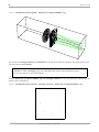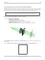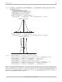
1
Rayica User Guide
1. Introduction
Loading Rayica
A basic Rayica example
Inputting data
Modelling an optical system
Variable definition
Basic Commands
Using Options
Rayica's high-level functions
2. Modeling Optical Components and Light Sources
Coordinates
Modeling a light source
Ray versus TurboRays
How Rayica manages default light source settings
Modeling an optical component
3. Introduction to the AnalyzeSystem and TurboPlot
4. The Move Function
5. Using AnalyzeSystem for Ray Tracing
Tracing a single ray
Working with the ray-trace data
6. The ShowSystem Function
7. Tracing a Cone of Rays
8. Adding a Cylindrical Lens to the System
3
3
4
4
5
5
6
7
8
9
9
9
12
14
16
18
19
20
20
21
22
24
26
2
Rayica User Guide
9. The RayChoice Option
10. Using Screen to Look at the Focal Plane
11. The ShowRange Option
12. The ReadRays Function
13. The PropagateSystem Function
14. Using TurboPlot for Ray Tracing and Rendering
AnalyzeSystem versus TurboPlot
CreateClones
15. Optimization with OptimizeSystem
16. ReadRays with TurboTrace and TurboPlot
17. Energy Calculations with FindIntensity
2-D Calculations with FindIntensity
FindFocus
Measuring the Point Spread Function
Measuring the Modulation Transfer Function
1-D Calculations with FindIntensity
18. The Resonate Function
19. Rayica's Database
20. The TransferTraits Function
21. What's Missing?
Features not discussed here
Features not covered in the basic package
Features left to the future
22. Backward Compatibility Issues
Single-User License Agreement
Contact Us
Optica Software Division of iCyt Mission Technology
2100 South Oak St., Champaign, IL 61820, USA.
voice 1-866-328-4298, fax 217.328.9692
[email protected]
©1994-2005 Optica Software. All rights reserved.
27
29
30
30
31
32
32
36
38
40
40
41
43
45
46
47
50
53
59
63
63
63
63
64
66
3
Rayica User Guide
1. Introduction
Nearly every optical engineering endeavor can benefit from the use of Rayica, including but not limited to: optimization,
lasers and resonators, non-sequential calculations, stray-light analysis, time-dependent optical systems, imaging systems,
spectroscopic measurement, astronomical systems, solar concentrators, fiber-optic systems, opto-mechanical systems,
polarization calculations, turbulent media, and photon-density calculations.
This guide will get you acquainted with Rayica's most important features. By learning the functions introduced here, you will
have a good foothold for using Rayica. In particular, you will learn how to model optical components and light sources
together for ray tracing as well as receive an overview of Rayica's most important capabilities. In addition to this User Guide,
advanced information is provided in the companion Principles Of Rayica guide as well as through our website:
www.opticasoftware.com. Before beginning, however, you must first load Rayica into memory.
Loading Rayica
The basic Rayica package is made up of two folders: Rayica and RayicaTools. The Rayica folder contains all of the essential
files that make up Rayica while RayicaTools contains auxiliary functions for loading packages and working with Mathematica. Make sure that both the Rayica and RayicaTools folders are located together in a directory path recognized by Mathematica for packages. The Rayica package is loaded with the following command:
In[1]:= Needs["Rayica`Rayica`"]
+++++++++++++++++++++++++
Rayica 2.0 was loaded in 18 s and needs 6019
kilobytes of memory on top of 3499 kilobytes already used
This loading process can take a minute or two, depending on your computer's speed. In addition to being loaded as a package,
all of Rayica files are formatted as Mathematica notebooks. The Rayica source code is made accessible in the Rayica folder
so that you can develop new functions of your own by studying Rayica's built-in functions. This is particularly helpful when
you wish to model new component ideas in Rayica.
©1994-2005 Optica Software. All rights reserved.
4
Rayica User Guide
A basic Rayica example
The simplest way to learn Rayica is to experiment with its text-based interface. To this end, we have included a series of
examples based on a simple optical system in this Introduction of the User Guide. The following series of examples will be
used to demonstrate the elements necessary to create and analyze a basic optical system in Rayica. Each line of the initial
example will be discussed in specific with references to later sections of this booklet for more extensive explanations of the
functions used.
In[13]:= TurboPlot[{
LineOfRays[45,NumberOfRays->11],
Move[PlanoConvexLens[100, 50, 10], 50],
Move[Screen[50], 200]
}]
Out[13]=
-traced system-
Inputting data
The first thing about this example to observe is the format. Because Rayica uses a text-based input system, it does not matter
whether or not you include line breaks where they have been included. They have been put into this example for the sake of
clarity. The generated image can be instantly resized by selecting a corner of the image and dragging the corner of the picture
until in is the desired size.
Another important note about entering data in Rayica is that every function in Rayica has a specific input format. For example, the input format for TurboPlot is TurboPlot[system, options]. TurboPlot takes two different inputs: an optical
system (system) and any option definitions (options). When any input variable contains multiple elements (in this case, an
optical system) it is necessary to enclose those elements in curly brackets (“ {}”). As with any mathematical system, it is
important to close all brackets and parentheses appropriately or else the calculation will fail. Note that sometimes an input
element is not required for final calculation. TurboPlot does not require that options be entered in order to perform a
calculation (nor does any other function for that matter). It is always valuable to check a functions definition to see whether
or not an input element is required for calculation or not.
©1994-2005 Optica Software. All rights reserved.
5
Rayica User Guide
Modelling an optical system
When entering an optical system into Rayica, you should consider what elements to include. To produce any meaningful
result, it is necessary to have two things: light sources and optical components. More often than not, you will have only one
light source but several components though only one of each has been included in this example. The light source is LineOfÖ
Rays and the optical component is PlanoConvexLens . Another essential element of this system is the Screen. While not
an optical element per se, the Screen provides a necessary function in that it intercepts all rays which come in contact with it
without changing the optical properties of the ray.
Just as important as the components and light sources that you include in an optical system is their position in the system. As
such, you will make almost constant use of the Move function. Move allows any object to be moved to any location or
position within an optical system. For more information on the Move function and its uses, see Section 4 of this guide.
The ultimate use of an optical system in Rayica is analysis and/or display. If you are unsure of the function that you wish to
use to analyze the optical system you have created, you can access a list of available functions using the RayicaFunctions
command.
Basic Steps to follow when creating an optical system:
1) Determine what light source to use
2) Create a component list (see the Resonate section if you have any composite lenses)
3) Position the components in your list using the Move function
4) Bound the system using a Screen or a Boundary
5) Assign the resulting system to a variable
6) Use different high level functions to analyze the system as necessary
Variable definition
It is an excellent idea to assign the system to a variable as shown below.
In[14]:= opticalsystem = {
LineOfRays[45,NumberOfRays->11],
Move[PlanoConvexLens[100, 50, 10], 50],
Move[Screen[50], 200]
}
Out[14]=
8LineOfRays@45, NumberOfRays Ø 11D,
Move@PlanoConvexLens@100, 50, 10D, 50.D, Move@Screen@50D, 200.D<
When an optical system is assigned to a variable, you can then use that variable to perform any number of calculations. It is
always a good idea to assign an optical system to a variable if you intend to use the same system for repeated calculations as
this can dramatically reduce input time. What is further, you can assign the output of a function to a variable as shown below
©1994-2005 Optica Software. All rights reserved.
6
Rayica User Guide
In[16]:= tracedresult = TurboPlot[opticalsystem]
Out[16]=
-traced system-
Basic commands
If you already know the name of command that you want to include in your optical system but would like to review the
definition before actually including it, you can use the ? command to display the definition.
In[11]:= ?PlanoConvexLens
PlanoConvexLens@focallength, aperture, thickness,
label, optionsD denotes a lens with a planar surface on
one side and a convex spherical surface on the other side.
PlanoConvexLens is created with its first surface centered about the origin
and its second surface positioned down the positive x axis. The aperture
parameter may designate a circle, rectangle, or polygon depending on
the number and type of elements listed by it. The user-named label
parameter is optional and can be omitted. When it is present, its text
content is used to identify the object in both the rendered graphics
and the output cell expression. When it is omitted, Rayica uses the
default setting of the Labels option with the rendered graphics.
Note that the specified focallength is always determined for a particular
setting of the DesignWaveLength and ComponentMedium options. By default,
Rayica uses DesignWaveLength->0.5461 microns and ComponentMedium->BK7.
Care should be taken to insure that these default settings are compatible
with the intended experimental design or unintended results can occur.
The ? command works with all defined elements of Rayica, from functions to light sources to options. Almost anything that
can be evaluated by Mathematica can be defined using the ? command.
Another very useful command is the % command. Use of % is discussed in the 10 minute introduction to Mathematica which
you may wish to read. Essentially, % acts as a variable which stores the result of the previous calculation. So, if you wish to
use the results of the last calculation performed, simply create a new input using % and evaluate it.
©1994-2005 Optica Software. All rights reserved.
7
Rayica User Guide
The final fundamental command is Options[ ]. When you enter a Rayica function name into the square brackets and press
Shift+Enter, a list of the options associated with that function name are displayed. Finding a rule and applying it will be
discussed in the next section.
In[12]:= Options[Screen]
Out[12]=
8Labels Ø S, LabelPositions Ø Automatic,
ComponentDescription Ø Automatic, Transmittance Ø 100, GraphicDesign Ø Automatic,
Automatic Ø 8SurfaceRendering Ø Trace, CrossRendering Ø Trace<,
Sketch Ø 8SurfaceRendering Ø Trace, CrossRendering Ø Trace<,
Wire Ø 8SurfaceRendering Ø Mesh, CrossRendering Ø Empty<,
Solid Ø 8SurfaceRendering Ø 8Fill, Trace<, CrossRendering Ø Empty<<
Using Options
Options are available for almost every element of Rayica. To discover what options are associated with the elements that you
are using, use the Options[] command as discussed in the Basic Commands section of this booklet. Options are assigned to
Rayica elements using what is known as a rule (“->”) in Mathematica. What this means is that you select an option (or
options) to assign a value (like PlotType in the following example) and then assign it a new value using the rule arrow.
In[17]:= TurboPlot[tracedresult, PlotType->TopView]
Out[17]=
-traced system-
If you are unsure of what new values can be assigned to an option, you can use the ? command and the option’s name to
determine what values can be assigned to that option.
In[18]:= ?PlotType
PlotType is an option of DrawSystemêAnalyzeSystem, TurboPlot, and
ShowSystem that designates the display form of the graphics rendering.
PlotType takes TopView, FrontView, SideView,
Full3D, RealTime3D, Off, Surface, and ShadowProject as values.
A list of one or two points specify a direction and center
to project the graphics. The points can be specified as rules
RaySelect -> sel, ComponentSelect -> sel and SurfaceSelect ->
sel, with sel being a list of selection properties passed to the
designated functions. See also: CreateStereoView and ProjectGraphics3D.
©1994-2005 Optica Software. All rights reserved.
8
Rayica User Guide
Rayica's high-level functions
Rayica has a number of functions available for high-level calculations. Some (but not all) of these functions are shown in the
following table.
AnalyzeSystem[system, options] is used to trace rays through optical components and render the results
for illustration purposes. This is also called DrawSystem.
PropagateSystem[system, options] is used by AnalyzeSystem to trace rays through optical components.
This method is much slower than TurboTrace.
TurboTrace[optics, options] produces an accelerated ray trace of a system of light sources and optical
elements.
TurboPlot[system, options] works with TurboTrace to perform accelerated ray-tracing and rendering of
a system of light sources and optical elements.
ShowSystem[system, options] takes a system of rays and/or components and generates a graphical display
of the system. ShowSystem works with AnalyzeSystem and TurboPlot results.
ReadRays[results, rayparameters, selectionproperties] takes ray-traced results from
AnalyzeSystem/TurboPlot/TurboTrace and returns a list of values for the rayparameters and
selectionproperties given.
OptimizeSystem[system, options] optimizes the performance of an optical system for a specified set of
symbolic input parameters.
FindFocus[objectset, options] determines the minimum spot size for a locus of rays at the last reported
surface in the system and plots the results.
FindSpotSize[objectset, options] determines the spot size for a locus of rays at the last reported surface in
the system and plots the results.
FindIntensity[system, options] calculates the intensity function for each optical surface that gets
reported from the ray trace of the system.
ModulationTransferFunction[intensitydata, options] calculates the modulation and phase transfer
functions of an optical system for a given object source input.
Resonate[listofcomponents, objectname, options] is a generic building block that causes a ray to be
nonsequentially traced within all of the surfaces defined by listofcomponents.
TransferTraits[donor-component, recipient-component, surfacenumbers, opts] is a function that
transfers the surface traits of a donor component surface into the surfaces (specified by surfacenumbers) of a
recipient component.
Rayica's most important high-level functions.
In various ways, these high-level functions assist the user in conducting the ray trace and interpreting the traced results. At
the heart of every high level function in Rayica is the ray-trace calculation. For this, Rayica offers two parallel ways to trace
rays through a system of optical elements in three-dimensional space, using either PropagateSystem or TurboTrace. In
many cases, however, the ray-trace needs to be accompanied by a graphical rendering of the traced system. In such instances,
either AnalyzeSystem or TurboPlot is called instead of PropagateSystem or TurboTrace. In other instances, ShowSysÖ
tem is used to render isolated components or to rerender the results after the initial trace has taken place. ReadRays is used
to extract numerical information from the traces previously conducted by AnalyzeSystem/PropagateSystem and TurboÖ
Plot/TurboTrace. The last five functions (OptimizeSystem , FindFocus, FindIntensity, ModulationTransferÖ
Function, and TransferTraits) are the highest level functions of all and perform very specific tasks, as indicated by their
given names.
Rayica offers four simple command tools that provide an overview of the functions used in the Rayica package: SourceFuncÖ
tions, ComponentFunctions, MoveFunctions, and RayicaFunctions. These four commands create a list of the
available light sources, optical components, move functions, and available optical functions respectively. For example, at any
time that you wish while working with Rayica, you can access a listing of Rayica's primary high-level functions with the
RayicaFunctions command:
©1994-2005 Optica Software. All rights reserved.
9
Rayica User Guide
In[7]:= RayicaFunctions
AddSurfaceRoughness
AnalyzeSystem
ConstructMeritFunction
DataToRayica
FindFocus
FindIntensity
FindSpotSize
Fresnel
Hole
ModulationTransferFunction
Move
MoveSurface
OptimizeSystem
ReadData
ReadRays
Resonate
SearchData
ShowSystem
TransferTraits
TurboPlot
TurboTrace
In Mathmatica, RayicaFunctions gives you hyperlinks to Rayica's most important high-level functions. Clicking
on any name will give you a description of its use.
Further, each of these lists is hyperlinked to the definitions of the different items contained in them. All you need to do is
click on an item in the list to have its description displayed. In this Guide, we will explore many of these different functions
in some detail. In some instances, this discussion serves as the primary reference for the subject matter. In other instances,
however, the subject is discussed in more detail elsewhere. Next, we will learn how to create models of optical components
and light sources.
2. Modeling Optical Components and Light Sources
Rayica has its own language for describing optical systems. In general, Rayica considers an optical system to be a collection
of light sources and optical components. There are many different types of components and light sources in Rayica and each
type is specified by a particular function. For example, a parallel light sheet is modeled by the LineOfRays function while a
mirror is modeled by the Mirror function. After evaluation, these functions generate one of two special data structures that
carry the optical properties. In particular, all component functions create a Component object, while all light source functions
create a Source object. In this section, you will learn how to use component functions and light source functions to model
optical components and light sources. Later on, you will learn how to define an optical system by listing together a combination of light sources and optical components. In particular, you will see that you can specify an optical system by placing
your light sources and components in a list whose order describes the order of the light propagation through the optical
components.
Coordinates
In Rayica, the X-axis runs in the horizontal direction, parallel to the computer screen, and is the default optical axis for
optical systems, components within systems, and surfaces within components. The Z-axis encompasses the vertical direction
and the Y-axis is right-handed with respect to the X and Z directions. Within an optical system, components and rays are
located using the system's "world" coordinate system. Each surface within a component has its own local coordinate system
and carries a three-dimensional rotation matrix plus a three-dimensional translation vector to transform a point or ray from
the “world” coordinate system into the surface's local coordinate system, and back. This world-to-surface transform (matrix
plus vector) is derived by combining the world-to-component and component-to-surface transforms during component
initialization.
Modeling a light source
Next, we will take a closer look at light source functions. Rayica has a built-in series of functions that model different
patterns of ray light sources. Here is a list of the most common built-in light source functions.
©1994-2005 Optica Software. All rights reserved.
10
Rayica User Guide
SingleRay[options] constructs a single ray of light with its starting position at the origin and is directed
down the positive x axis.
CircleOfRays[seed, size, options] initializes a set of rays distributed on the surface of a tube that points
down the positive x-axis.
ConeOfRays[seed, spread, options] initializes a set of rays distributed along a funnel-shaped surface that is
oriented down the positive x-axis.
WedgeOfRays[seed, spread, options] initializes a set of rays in the x-y plane that fan out with their chief
direction oriented down the positive x-axis and are distributed across the y-coordinate with the specified fan
spread.
LineOfRays[seed, linewidth, options] initializes a set of rays in the x-y plane that point down the positive
x-axis and are distributed along the y-coordinate with the specified linewidth.
GridOfRays[seed, size, options] initializes a set of rays distributed throughout a tube-shaped volume that
points down the positive x-axis.
PointOfRays[seed, spread, options] initializes a set of rays distributed throughout a funnel-shaped volume
that is oriented down the positive x-axis.
CustomRays[seed, {{name, vector}..}, options] initializes a set of user-defined rays.
GaussianBeam[beamspotsize, fulldivergence, options] and GaussianBeam[complexbeamparameter,
options] is a light source that takes either the output beam spotsize radius (specified at 1/e of the axial value
of the electric field amplitude peak in the starting plane) and far-field beam fulldivergence (specified as the
full angle in radians at 1/e^2) or the complex beam parameter as input and creates an extended point source
ray model of a Gaussian laser beam.
RainbowOfRays[seed, {minwavelength, maxwavelength}, options] initializes a set of overlapping rays that
point down the positive x-axis and are distributed over the specified range of wavelengths, given in microns.
Ten commonly used light source functions.
At any time that you wish while working with Rayica, you can access a listing of Rayica's main high-level light source
functions with the SourceFunctions command:
In[8]:= SourceFunctions
CircleOfRays
ConeOfRays
CustomRays
GaussianBeam
GridOfRays
LineOfRays
PointOfRays
RainbowOfRays
SingleRay
WedgeOfRays
In Mathmatica, SourceFunctions gives you hyperlinks to Rayica's most important light-source functions.
Clicking on any name will give you a description of its use.
Most light sources in Rayica generate multiple rays of light. However, the simplest type of light source is the SingleRay
function. This is designed for applications that require a single ray to be traced. When multiple rays are required, you could
in principle specify a list of SingleRay functions for each ray, but it is always faster and more memory efficient to use one
of the other built-in light source functions instead.
In Rayica, each light source function generates the information needed to describe a particular pattern of geometric rays. You
can either store this generated information in an intermediate variable or immediately use it in a ray-trace calculation. Here is
how you evaluate the SingleRay function and assign its information to a variable called lightsource.
©1994-2005 Optica Software. All rights reserved.
11
Rayica User Guide
In[16]:=
lightsource = SingleRay[]
Out[16]=
SingleRay@D
Rayica normally hides the contents of its light sources by echoing the function input back to the screen. For a first-time user
of Rayica, this can be a bit disconcerting since it appears that nothing has occurred at all. For this reason, Rayica changes the
returned text color (typically to green) for valid entries instead of using the default black color of ordinary Mathematica
output. This color change indicates that the input has been correctly evaluated by Rayica. If there is no color change, then the
function has not been recognized by Rayica and, most likely, there has been a typographical mistake. In addition, if you use
InputForm, as shown below, you can see that the SingleRay function has actually generated a hidden packet of information that is encapsulated by a Source object.
In[3]:= lightsource//InputForm
Out[3]//InputForm=
Source[{}, SourceDescription :> SourceDescription[SingleRay[{Ray[]}, 1,
SourceTransformation ->
{{0., 0., 0.}, {{1., 0., 0.}, {0., 1., 0.}, {0., 0., 1.}}},
SymbolicSourceTransformation ->
{{0, 0, 0}, {{1, 0, 0}, {0, 1, 0}, {0, 0, 1}}}]], SourceTransformation :>
{{0, 0, 0}, {{1, 0, 0}, {0, 1, 0}, {0, 0, 1}}}, SymbolicSourceTransformation :>
{{0, 0, 0}, {{1, 0, 0}, {0, 1, 0}, {0, 0, 1}}}, SourceLevel :> {1, 1}, NumberOfRays
:> 1, BirthPoint :> {0, 0, 0},
CoordinateSystem :> CartesianCoordinates, StartAtBirthPoint :> True, MonteCarlo :>
False, SourceID :> 576,
SourceFraction :> 1, SourceOffset :> 0, GridSpacing :> (#1 & )]
Because the Source object is automatically created by all of the built-in light source functions, the user of Rayica never has
to worry about the contents of this object. In fact, unless you use InputForm, as demonstrated here, you will never even see
the contents of another Source object again after this discussion! Nevertheless, it is helpful to understand what happens
when you evaluate a light source function (ie: it creates a Source object.) This information is used later by Rayica for
ray-tracing. In the previous result, the "SingleRay[ ]" returned to the screen merely identified the type of function that
generated the Source object, namely by SingleRay! In advanced forms of Rayica, this "self-echoing" feature enables
Rayica to support GUI-mouse gestures in addition to the textual entry of optics. For the basic Rayica operation discussed
here, however, we will only consider the textual entry of optics.
A Source object is not directly used for the ray-trace calculation. Rather, the Source information is only used at the start of
the ray trace to initiate the rays for the trace. Essentially, the Source object informs Rayica how create the required rays at
the start of the ray trace. In particular, the Source object indicates which type of function has created it (SingleRay in this
case) and includes special instructions about how many rays are to be created as well as how to configure the created rays
into a particular spatial pattern. All of Rayica's light source functions generate a Source object in the same fashion as
SingleRay. Each light source function always creates a single Source object regardless of the actual number of rays used in
the trace. After a ray trace has been carried out, specific information is usually returned about the optical surface intersections
encountered by the rays in the trace. However, Source objects are only used to initiate the trace and are not used to store the
resulting information from the ray trace. Instead, the traced rays are stored either as Ray objects (with AnalyzeSystem/PropÖ
agateSystem) or as TurboRays objects (with TurboPlot/TurboTrace). In the next section, you will learn more about
Ray and TurboRays objects and how they get created from Source objects by the ray-trace functions of Rayica.
©1994-2005 Optica Software. All rights reserved.
12
Rayica User Guide
Ray versus TurboRays
In this section, we will examine how PropagateSystem and TurboTrace store ray information as either Ray or TurboÖ
Rays objects. In general, however, the user of Rayica will never work directly with Ray and TurboRays objects. As such,
the following discussion is simply provided to help the user gain further insight into how Rayica's handles the ray-trace
information. For the most part, these mechanisms are hidden away from the Rayica user. If you are learning about Rayica for
the very first time, you can skip this section without penalty.
At the start of a ray-trace, both PropagateSystem and TurboTrace use the CreateRays function to convert Source
objects into either Ray or TurboRay objects. This initializes the ray information for the trace.
CreateRays[source, options] is used by PropagateSystem and TurboTrace to generate either Ray
objects or a TurboRays object that represents a set of rays for the given light source.
Ray[rules] contains rules that is used by PropagateSystem to characterize a single ray segment of light
between two optical surfaces.
TurboRays[{raysegment1, raysegment2, ...}] gives a collection of ray segment parameters for use with
TurboTrace.
The Ray and TurboRays objects offer two parallel ways of storing the same information about rays. In particular, the Ray
object is used by PropagateSystem to hold ray information, while the TurboRays object is used instead by TurboTrace.
As an example, we will use the WedgeOfRays function to generate three rays. First, we will assign the WedgeOfRays result
into a variable, called wedgeofrays.
In[20]:= wedgeofrays = WedgeOfRays[10]
Out[20]=
WedgeOfRays@10D
With InputForm, we can see that, like SingleRay, WedgeOfRays also creates a single Source object. However, this
Source object defines a wedge-shaped pattern of three rays.
In[23]:= wedgeofrays//InputForm
Out[23]//InputForm=
Source[{}, SourceDescription :> SourceDescription[WedgeOfRays[{Ray[]}, 10,
SourceTransformation -> {{0., 0., 0.}, {{1., 0., 0.}, {0., 1., 0.}, {0., 0.,
1.}}},
SymbolicSourceTransformation -> {{0, 0, 0}, {{1, 0, 0}, {0, 1, 0}, {0, 0, 1}}}]],
SourceTransformation :> {{0, 0, 0}, {{1, 0, 0}, {0, 1, 0}, {0, 0, 1}}},
SymbolicSourceTransformation :> {{0, 0, 0}, {{1, 0, 0}, {0, 1, 0}, {0, 0, 1}}},
SourceLevel :> {1, 1},
NumberOfRays :> 3, BirthPoint :> {0, 0, 0}, CoordinateSystem :> PolarCoordinates,
StartAtBirthPoint :> True,
MonteCarlo :> False, SourceID :> 2118, SourceFraction :> 1, SourceOffset :> 0,
GridSpacing :> (#1 & ),
PowerOutput :> 100, SymbolicValues :> {}]
Next, we will demonstrate how CreateRays is used by PropagateSystem to initialize the ray information as Ray objects.
When we apply CreateRays to wedgeofrays, there are three Ray objects generated.
©1994-2005 Optica Software. All rights reserved.
13
Rayica User Guide
In[22]:= CreateRays[wedgeofrays]//InputForm
Out[22]//InputForm=
{Ray[Intensity :> 100., IntensityScale :> 1., OpticalMedium :> Air, Polarization :>
{0., 1., 0.},
RayEnd :> {0., 0., 0.}, RayLabelPositions :> {{0., 0., 0.}}, RayLength :> 0.,
RayLineRGB :> Automatic,
RayPointRGB :> {0., 0., 0.}, RaySourceNumber -> {{1, 3}, {1, 0}}, RayStart :> {0.,
0., 0.},
RayTilt :> {0.9961946980917455, 0.08715574274765817, 0.}, RefractiveIndex :>
1.0002694514570802,
RotationMatrix :> {{0.9961946980917455, 0.08715574274765817, 0.},
{-0.08715574274765817, 0.9961946980917455, 0.},
{0., 0., 1.}}, SourceID :> 2118, SourceTransformation :> {{0., 0., 0.}, {{1., 0.,
0.}, {0., 1., 0.}, {0., 0., 1.}}},
WaveFrontID :> {{2118, 0}}], Ray[Intensity :> 100., IntensityScale :> 1.,
OpticalMedium :> Air,
Polarization :> {0., 1., 0.}, RayEnd :> {0., 0., 0.}, RayLabelPositions :> {{0., 0.,
0.}}, RayLength :> 0.,
RayLineRGB :> Automatic, RayPointRGB :> {0., 0., 0.}, RaySourceNumber -> {{2, 3},
{2, 0}}, RayStart :> {0., 0., 0.},
RayTilt :> {1., 0., 0.}, RefractiveIndex :> 1.0002694514570802,
RotationMatrix :> {{1., 0., 0.}, {0., 1., 0.}, {0., 0., 1.}}, SourceID :> 2118,
SourceTransformation :> {{0., 0., 0.}, {{1., 0., 0.}, {0., 1., 0.}, {0., 0., 1.}}},
WaveFrontID :> {{2118, 0}}],
Ray[Intensity :> 100., IntensityScale :> 1., OpticalMedium :> Air, Polarization :>
{0., 1., 0.},
RayEnd :> {0., 0., 0.}, RayLabelPositions :> {{0., 0., 0.}}, RayLength :> 0.,
RayLineRGB :> Automatic,
RayPointRGB :> {0., 0., 0.}, RaySourceNumber -> {{3, 3}, {3, 0}}, RayStart :> {0.,
0., 0.},
RayTilt :> {0.9961946980917455, -0.08715574274765817, 0.}, RefractiveIndex :>
1.0002694514570802,
RotationMatrix :> {{0.9961946980917455, -0.08715574274765817, 0.},
{0.08715574274765817, 0.9961946980917455, 0.},
{0., 0., 1.}}, SourceID :> 2118, SourceTransformation :> {{0., 0., 0.}, {{1., 0.,
0.}, {0., 1., 0.}, {0., 0., 1.}}},
WaveFrontID :> {{2118, 0}}]}
Here, each Ray object represents a different ray segment. When TurboTrace is used for ray-tracing, it works instead with a
TurboRays object. The OutputType option is used with CreateRays to determine whether CreateRays generates a Ray
object or a TurboRays object from the Source information. By default, CreateRays creates Ray objects. However, when
TurboTrace calls CreateRays, it passes OutputType -> TurboRays to obtain a TurboRays object. Next we apply
CreateRays to wedgeofrays for a second time with OutputType -> TurboRays.
©1994-2005 Optica Software. All rights reserved.
14
Rayica User Guide
In[21]:= CreateRays[wedgeofrays, OutputType -> TurboRays]//InputForm
Out[21]//InputForm=
TurboRays[{{0., 0., 0., 0., 0., 0., 0.9961946980917455, 0.08715574274765817, 0.,
-0.08715574274765817,
0.9961946980917455, 0., 0., 0., 1., 0.532, 100., 0.33333333333333337, 0.,
1.0002694514570802, 0., 0., 0., 0., 0., 0.,
0., 2118., 2118., 1., 3., 1., 0., 1., 0., 0., 0., 1., 0.}, {0., 0., 0., 0., 0., 0.,
1., 0., 0., 0., 1., 0., 0., 0.,
1., 0.532, 100., 0.33333333333333337, 0., 1.0002694514570802, 0., 0., 0., 0., 0.,
0., 0., 2118., 2118., 2., 3., 2.,
0., 1., 0., 0., 0., 1., 0.}, {0., 0., 0., 0., 0., 0., 0.9961946980917455,
-0.08715574274765817, 0.,
0.08715574274765817, 0.9961946980917455, 0., 0., 0., 1., 0.532, 100.,
0.33333333333333337, 0., 1.0002694514570802,
0., 0., 0., 0., 0., 0., 0., 2118., 2118., 3., 3., 3., 0., 1., 0., 0., 0., 1., 0.}}]
This time, only a single TurboRays object is produced that contains three sets of numbers. In this case, each set of numbers
represents a different ray segment. From this, we can see that TurboRays is much more efficient at holding information than
Ray objects! This is gives TurboTrace the ability to work with very large ray-data sets and consume less memory. However, the Ray object is much more flexible at holding different sorts of optical parameters, such as user-defined parameters.
This, in turn, gives PropagateSystem added flexibility over TurboTrace for tracing customized information. In general,
however, the user of Rayica will never work directly with Ray and TurboRays objects and these conversions happen
transparently. In the next section, we will learn about Options[Ray]. Options[Ray]is used by CreateRays to fill in any
essential ray parameters missing from the specified Source object during its ray creation.
How Rayica manages default light source settings
In Rayica as well as Mathematica, most built-in functions have a way to pass default settings about certain parameters. This
relieves the user from always having to specify all possible parameters required by the function to operate. Such default
parameters are referred to as "options" because you can optionally decide to change the setting of such a parameter (but you
don't have too!) As you will see shortly, each option follows the pattern: optionlabel -> optionvalue. (Such a pattern is also
called a "rule" because it is internally evaluated by Mathematica as: Rule[optionlabel, optionvalue] .) As with all other types
of Rayica's light source functions, SingleRay[] has many options that help describe the generated ray.
Since all types of light sources must make the same basic assumptions about their created rays, Rayica uses a single location,
called Options[Ray], to store this information. The most important of these settings include physical attributes, such as:
wavelength, polarization, intensity, and optical length. However, there are also a number of other non-physical attributes as
well. You can check these default assumptions by examining the contents of Options[Ray].
©1994-2005 Optica Software. All rights reserved.
15
Rayica User Guide
In[4]:= Options[Ray]
Out[4]=
8ComponentIncrement Ø Automatic, ComponentNumber Ø ComponentNumber,
ConfinedNumber Ø ConfinedNumber, ConfinedPosition Ø ConfinedPosition,
DiffractionMismatch Ø DiffractionMismatch,
DiffractionOrderNumber Ø DiffractionOrderNumber, GenerationNumber Ø GenerationNumber,
Intensity Ø 100., InternalDirectionChange Ø False,
IntersectionNumber Ø IntersectionNumber, IntrinsicMedium Ø Air,
NewAuthorizedOptions Ø NewAuthorizedOptions, OffAxis Ø OffAxis, OpticalLength Ø 0.,
OpticalMedium Ø Automatic, Polarization Ø 80., 1., 0.<, RayEnd Ø 80., 0., 0.<,
RayLabelPositions Ø 880., 0., 0.<<, RayLabels Ø 8<, RayLength Ø 0., RayLineRGB Ø Automatic,
RayLineStyle Ø 8<, RayLineThickness Ø 0.5, RayPointRGB Ø 80., 0., 0.<,
RayPointSize Ø 2., RayPointStyle Ø 8<, RaySourceNumber Ø RaySourceNumber,
RayStart Ø 80., 0., 0.<, RayTilt Ø 81., 0., 0.<, RefractiveIndex Ø Automatic,
RotationMatrix Ø 881., 0., 0.<, 80., 1., 0.<, 80., 0., 1.<<, SourceID Ø Automatic,
SourceTransformation Ø 880., 0., 0.<, 881., 0., 0.<, 80., 1., 0.<, 80., 0., 1.<<<,
SurfaceBoundary Ø SurfaceBoundary, SurfaceCoordinates Ø SurfaceCoordinates,
SurfaceID Ø SurfaceID, SurfaceIncrement Ø 1, SurfaceNormalMatrix Ø SurfaceNormalMatrix,
SurfaceNumber Ø SurfaceNumber, SymbolicWaveLength Ø SymbolicWaveLength,
Temperature Ø 20., Tension Ø 88101300., 0., 0.<, 80., 101300., 0.<, 80., 0., 101300.<<,
UnconfinedIncrement Ø 1, UnconfinedPath Ø UnconfinedPath,
UnconfinedPosition Ø UnconfinedPosition, WaveFrontID Ø Automatic, WaveLength Ø 0.532<
Options[Ray] applies to all of Rayica's light sources since it determines what default values will be used by the rays at the
start of the trace. In some cases, a parameter many not have a specific initial setting. In such cases, the optionvalue is given
the same name as the optionlabel. In other cases, the optionvalue can simply be written as Automatic. In such a case, the
option value is dynamically assigned. Regardless of its setting, every possible option parameter is listed in Options for the
benefit of the user to know either that it exists or that it can be altered with a user-specified value.
In order to specify a new ray parameter setting, you simply pass the changed option setting as a parameter. For example, to
change the wavelength setting to 0.633 microns, you would use:
In[15]:= SingleRay[WaveLength -> .633]
Out[15]=
SingleRay@WaveLength Ø 0.633D
In this case, a subsequent ray-trace would use this new wavelength setting. In addition, SingleRay also has its own set of
options that specifically applies to only the SingleRay function. These are found in Options[SingleRay]:
In[3]:= Options[SingleRay]
Out[3]=
8NumberOfRays Ø 1, BirthPoint Ø Automatic, SymbolicBirthPoint Ø BirthPoint,
CoordinateSystem Ø CartesianCoordinates, StartAtBirthPoint Ø True,
BalancePhaseFront Ø True, MonteCarlo Ø False, SourceOffset Ø 0,
SourceFraction Ø 1, GridSpacing Ø H#1 &L, IntensityFunction Ø H#1 &L,
PolarizationFunction Ø H#1 &L, SourceID Ø Automatic<
In the same manner as SingleRay, all other built-in light source functions also have their own specific option settings that
are accessed with their function name, given by Options[function name]. In fact, a good way to learn more about any
unfamiliar function in Rayica (or Mathematica) is to have a look at its built-in options because this often gives you a clue
about the range of behaviors that the function can exhibit. You can learn more about Rayica's built-in light source functions
in Section 1.3.4 of the Principles of Rayica Guide.
©1994-2005 Optica Software. All rights reserved.
16
Rayica User Guide
Modeling an optical component
Rayica has many more functions for modelling optical components than it has for light sources. In fact, there are presently
122 component functions in common use. At any time that you wish while working with Rayica, you can access a listing of
the component functions with the ComponentFunctions command:
In[9]:= ComponentFunctions
ABCDOptic
AnamorphicPrisms
ApertureStop
AsphericLens
AsphericLensSurface
AsphericMirror
Baffle
CustomDiffuserMirror
CustomFiber
CustomFiberMirror
CustomGrating
CustomGratingMirror
CustomLens
CustomLensSurface
LensDoublet
LensSurface
LensTriplet
LinearPolarizer
Mirror
MirrorSpan
ParabolicDiffuser
RodMirror
RoofPrism
SchmidtLens
SchmidtLensSurface
Screen
SlabPrism
SnowConeLens
BaffleSpan
BaffleWithHole
CustomMirror
CustomPrism
ParabolicDiffuserMirror
ParabolicLensSurface
SolidCornerCube
Solitaire
BallBaffle
BallLens
BallMirror
BeamSplitter
CustomScreen
CylinderGraphic
CylindricalBaffle
CylindricalLens
ParabolicMirror
PechanPrism
PellinBrocaPrism
PentaPrism
SphereGraphic
SphericalBaffle
SphericalBeamSplitter
SphericalDiffuser
BeamSplitterCube
BiConcaveCylindricalLens
BiConcaveLens
CylindricalLensSurface
CylindricalMirror
CylindricalScreen
PinHole
Pipe
PlanoConcaveCylindricalLens
SphericalDiffuserMirror
SphericalGratingMirror
SphericalLens
BiConvexCylindricalLens
BiConvexLens
BirefringentLensSurface
Boundary
Diffuser
DiffuserMirror
DirectVisionPrism
DovePrism
PlanoConcaveLens
PlanoConvexCylindricalLens
PlanoConvexLens
PolarizingBeamSplitterCube
SphericalLensSurface
SphericalMirror
SphericalScreen
SquareConeMirror
Box
BoxGraphic
CircleGraphic
DTIRCLens
DTIRCLensSurface
Fiber
PolarizingPrism
PolygonalMirror
PolygonGraphic
SurfaceFacet
ThickLens
ThinLens
ClearBoundary
CompoundLens
ConjugateMirror
FresnelRhomb
FunnelLens
FunnelLensSurface
PorroPrism
Prism
RectangleGraphic
ToroidalLens
ToroidalLensSurface
ToroidalMirror
CustomBaffle
Grating
RetardationPlate
WedgePrism
CustomBeamSplitter
CustomBirefringentLensSurface
CustomConjugateMirror
GratingMirror
HalfBallLens
HollowCornerCube
ReversionPrism
RhomboidPrism
RodBaffle
Window
WinstonConeMirror
CustomDiffuser
JonesMatrixOptic
RodLens
In Mathmatica, ComponentFunctions gives you hyperlinks to Rayica's current component functions. Clicking on
any name will give you a description of its use.
In addition to ones listed here, you can build your own custom component functions as well as download new functions from
the Optica Software web-site (www.opticasoftware.com). One of the most frequently used component functions is PlanoConÖ
vexLens.
PlanoConvexLens[ focallength, aperture, thickness, options] refers to a lens with a planar surface on one
side and a convex spherical surface on the other side.
Here is how you evaluate the PlanoConvexLens function.
©1994-2005 Optica Software. All rights reserved.
17
Rayica User Guide
In[18]:= PlanoConvexLens[100, 50, 10]
Out[18]=
PlanoConvexLens@100, 50, 10D
In the same fashion that ray source functions create Source objects, every component function creates a Component object.
In this PlanoConvexLens example, hidden behind the "PlanoConvexLens[100,50,10]" output returned to the screen is a
very large expression that is encapsulated with the Component head. It contains detailed information to describe a plano-convex lens having a focal length of 100 millimeters, a circular aperture 50 millimeters in diameter, and a lens center thickness
of 10 millimeters. Instead of showing this entire expression, Rayica always hides the contents of Component by outputting
back to the screen a description of how the component was generated. Here again, Rayica indicates a valid entry by returning
the text in a different color from black.
As with light source functions and the Source object, since the Component object is automatically created by the built-in
component functions, the user of Rayica will never need to worry about the details of this Component object. In fact, unless
you use InputForm, as demonstrated previously with the Source object, the contents of the Component object are always
hidden. Nevertheless, it is helpful to understand what happens when you evaluate a component function.
As with light sources, you can use these generated Component objects immediately after creating them for doing ray tracing
and rendering, or you can assign them to a variable for future work. While focallength, aperture, and thickness are all parameters given explicitly to the PlanoConvexLens function, other implicit parameters, such as the type of refractive material are
kept as options of PlanoConvexLens. You can use Options[PlanoConvexLens] to access the default options of PlanoÖ
ConvexLens.
In[30]:= Options[PlanoConvexLens]
Out[30]=
8Labels Ø L, LabelPositions Ø Automatic, ComponentDescription Ø Automatic,
ComponentMedium Ø BK7, Temperature Ø Temperature, Tension Ø Tension,
Transmittance Ø Transmittance, Reflectance Ø Reflectance,
GraphicDesign Ø Automatic, CurvatureDirection Ø Front,
DesignWaveLength Ø 0.5461, OffAxis Ø 80, 0<, SwitchDirectionOnReflection Ø False,
Resonate Ø True, Automatic Ø 8SurfaceRendering Ø Empty,
EdgeRendering Ø Mesh, CrossRendering Ø 88Fill, Trace<<<, Sketch Ø
8SurfaceRendering Ø Trace, EdgeRendering Ø Empty, CrossRendering Ø 88Fill, Trace<<<,
Wire Ø 8SurfaceRendering Ø Mesh, EdgeRendering Ø Mesh, CrossRendering Ø 88Fill, Trace<<<,
Solid Ø
8SurfaceRendering Ø 88Fill, Trace<<, EdgeRendering Ø Fill, CrossRendering Ø Empty<<
Notice the option ComponentMedium -> BK7. This option indicates that the refractive material of the planoconvex lens is
assumed to be made of BK7 glass material. Here, the BK7 symbol specifies a particular wavelength-dependent model for the
refractive index. However, you can also specify a fixed numeric value for ComponentMedium, as shown below. In this case,
the refractive index is held constant for all wavelength values.
In[19]:= PlanoConvexLens[100, 50, 10, ComponentMedium -> 1.5]
Out[19]=
PlanoConvexLens@100, 50, 10, 8ComponentMedium Ø 1.5<D
©1994-2005 Optica Software. All rights reserved.
18
Rayica User Guide
3. Introduction to AnalyzeSystem and TurboPlot
Rayica has two parallel methods for doing ray-tracing and rendering of optical systems. One method uses the AnalyzeSysÖ
tem function (originally known as DrawSystem), while the second method uses the TurboPlot function. Each method
offers similar functionally in a parallel way. AnalyzeSystem is good for generating illustrations for publication and tracing
small numbers of rays while TurboPlot is best for working with large numbers of rays. After making some initial comparisons between these two methods, we will next consider the use of AnalyzeSystem. The application of TurboPlot will be
explored further in Section 15.
AnalyzeSystem[objectset, options] uses PropagateSystem and ShowSystem to trace rays through
optical components and render the results.
TurboPlot[system, options] works with TurboTrace to perform accelerated ray-tracing and rendering of
a system of light sources and optical elements.
Both AnalyzeSystem and TurboPlot call other intermediate functions for their internal operations of ray-tracing and
graphical rendering. They simply provide a single convenient interface for the Rayica user to conduct the ray-tracing and
rendering. Both AnalyzeSystem and TurboPlot are used in the same fashion, as each accepts a list of light source and
component functions for input. One key difference between AnalyzeSystem and TurboPlot is that AnalyzeSystem uses
the interpreted language of Mathematica for ray-tracing while TurboPlot uses a highly-efficient, compiled function, which
is more time-consuming to create initially but then performs the actual ray trace much faster. As a result of this, when only a
small number of rays are needed, AnalyzeSystem can sometimes deliver a result more quickly than TurboPlot. In addition, AnalyzeSystem often works better than TurboPlot for the creation of optical schematics and illustrations for publication, since it is tailored for such purposes. However, it is always more advantageous to use TurboPlot and TurboTrace
when large numbers of rays or iterative processes are required.
We will now consider AnalyzeSystem in more detail. When no light sources are included, AnalyzeSystem simply renders
the optical components present. Here we use AnalyzeSystem to render a plano-convex lens.
In[20]:= AnalyzeSystem[PlanoConvexLens[100, 50, 10], Axes -> True]
20
0
-20
20
0
-20
0 5
2.5
7.5
10
AnalyzeSystem@8PlanoConvexLens@100, 50, 10D<D
Out[20]=
-rendered element-
Here, PlanoConvexLens is created with its first surface at the origin and its second surface positioned down the positive x
axis. In general, the aperture parameter of PlanoConvexLens may designate a circle, rectangle, or polygon, depending on
the number and type of elements listed by it. Here we created a circular lens that has a diameter of 50 millimeters by using
50 in the aperture parameter. After rendering the plano-convex lens, AnalyzeSystem first echoes back the input expres©1994-2005 Optica Software. All rights reserved.
sion, and then returns the actual information (hidden
within the -rendered element- expression). Shortly, in Section 7, we will
use AnalyzeSystem for ray-tracing as well as rendering, but first we must learn how to position optical components and
light sources in three-dimensional space.
19
Rayica User Guide
Here, PlanoConvexLens is created with its first surface at the origin and its second surface positioned down the positive x
axis. In general, the aperture parameter of PlanoConvexLens may designate a circle, rectangle, or polygon, depending on
the number and type of elements listed by it. Here we created a circular lens that has a diameter of 50 millimeters by using
50 in the aperture parameter. After rendering the plano-convex lens, AnalyzeSystem first echoes back the input expression, and then returns the actual information (hidden within the -rendered element- expression). Shortly, in Section 7, we will
use AnalyzeSystem for ray-tracing as well as rendering, but first we must learn how to position optical components and
light sources in three-dimensional space.
4. The Move Function
To put an optical element at a location other than x = 0, y = 0, and z = 0, you will need to use one of Rayica's positioning
directives. The most important positioning directive in Rayica is the Move function. You can use Move to position both light
sources and rays in space. The basic definition for Move is shown below.
Move[objectset, {x, y}, rotationangle, options] is used to move the relative position and orientation of a set
of components and rays within a horizontal plane.
Here, the rotationangle determines the angular orientation of the object set within the horizontal plane. You can use the
TwistAngle -> angle option to specify a rotation angle around the axis of orientation. Next we will use Move together with
AnalyzeSystem to draw two lenses spaced apart from each other. Place the first one at x = 0, y = 0, with no rotation, and a
second one at x = 100, y = 10, with a 45-degree rotation.
In[21]:= AnalyzeSystem[{
PlanoConvexLens[100, 50, 10],
Move[PlanoConvexLens[100, 50, 10], {100, 10}, 45]}, Axes -> True]
20
0
-20
0
20
50
0
100
-20
AnalyzeSystem@
8PlanoConvexLens@100, 50, 10D, Move@PlanoConvexLens@100, 50, 10D, 8100., 10.<, 45.D<D
Out[21]=
-rendered system without rays-
©1994-2005 Optica Software. All rights reserved.
20
Rayica User Guide
Note that, again, the text output returned to the screen mimics the original input expressions, when, in fact, a great quantity of
information is hidden behind the "-rendered system without rays-" statement. Although only a single format has been shown
previously for Move, there are actually a variety of input formats used with Move. These are shown below.
Move[objectset, {x, y}, rotationangle]
Move[objectset, x, rotationangle]
Move[objectset, x]
Move[objectset, {x, y}]
Move[objectset, {x, y, z}]
Move[objectset, {x, y, z}, axisvector]
Move[objectset, {x, y, z}, axisvector, twistangle]
Move[objectset, {x, y, z}, rotationmatrix]
Common input formats for Move. Although not shown, these formats all accept options.
Including the Move function, Rayica has eight positioning directives. At any time that you wish while working with Rayica,
you can access a listing of Rayica's positioning functions with the MoveFunctions command:
In[10]:= MoveFunctions
Move
MoveDirected MoveReflected Rotate
MoveAligned MoveLinear
MoveSurface
Translate
In Mathmatica, MoveFunctions gives you hyperlinks to Rayica's most important positioning functions. Clicking
on any name will give you a description of its use.
You can learn more about how to use Move and the other directives in Chapter 2, the Placement Directives chapter, of the
Principles of Rayica discussion.
5. Using AnalyzeSystem for Ray Tracing
Tracing a single ray
We are almost ready to use AnalyzeSystem for ray-tracing. First, however, we need to consider a boundary to contain the
rays. Otherwise, the traced rays will terminate on the last surface of the last optical component in the system. The easiest way
to define a boundary is with the Boundary function. Before continuing with the ray trace, lets first examine the Boundary
function in more detail.
Boundary[boundaryparameters] denotes a rectangular box that absorbs rays intercepted by its walls.
There are three methods for specifying boundaryparameters: Boundary[{x1, y1, z1}, {x2, y2, z2}] uses the coordinates of
top and bottom opposite corners of a rectangular box, Boundary[side] assumes a cube boundary, and Boundary[aside,
bside] assumes a three-dimensional box having a length specified by aside, a width specified by bside, and a height specified
by bside. Optical systems propagating rays usually have at least one boundary component listed at the end. In this example,
we will use Boundary[200].
©1994-2005 Optica Software. All rights reserved.
21
Rayica User Guide
We can now use AnalyzeSystem for ray tracing. For this, we will trace a single ray through a lens using the SingleRay,
PlanoConvexLens , and Boundary functions. This time we will store the ray-trace result in a variable called trace. This
will allow us to examine the traced information later on with other functions.
In[22]:= trace = AnalyzeSystem[{
SingleRay[],
Move[PlanoConvexLens[100, 50, 10], {100, 10}, 45],
Boundary[200, 70]}]
AnalyzeSystem@8SingleRay@D, Move@PlanoConvexLens@100, 50, 10D, 8100., 10.<, 45.D,
Boundary@80, -35, -35<, 8200, 35, 35<D<D
Out[22]=
-3 rayêsurface intersections-
By default, Rayica always takes the x-axis to be the optical axis. This means that, by default, all of Rayica's built-in light
source functions automatically direct their rays along the positive x-axis. In this example, the SingleRay function has
generated a ray that is exactly co-linear with the x-axis. In other, more complex light source functions, only the chief ray is
precisely co-linear with the x-axis. Of course, you can always choose a different optical axis by re-aligning the light source
and optics with a positioning directive such as Move.
Working with the ray-trace data
After calculating and rendering the ray trace, AnalyzeSystem passes back a data object that holds the ray-trace information.
You can use this returned information to make further plots or exact numeric information about the generated ray trace. In
general, depending on whether AnalyzeSystem or TurboPlot was used, the final ray-trace data is held in either an OptiÖ
calSystem object (as in this case) or a TurboSystem object (with TurboPlot). However, as discussed before with CompoÖ
nent and Source, the information held in these returned objects are always hidden from the user. Rather than directly
viewing these objects, you will normally examine the ray-trace results with one of Rayica's ray-trace diagnostic functions.
These are listed below.
©1994-2005 Optica Software. All rights reserved.
22
Rayica User Guide
ShowSystem[system, options] takes a system of rays and/or components and generates a graphical display
of the system.
ReadRays[results, rayparameters, selectionproperties] takes ray-traced results from
AnalyzeSystem/PropagateSystem as well as TurboPlot/TurboTrace and returns a list of values for
rayparameters given.
FindFocus[system, options] determines the minimum spot size for a locus of rays at the last reported
surface in the system and plots the results.
FindSpotSize[objectset, options] determines the spot size for a locus of rays at the last reported surface in
the system and plots the results.
FindIntensity[system, options] calculates the intensity function for each optical surface that gets
reported from the ray trace of the system.
ModulationTransferFunction[intensitydata, options] calculates the modulation and phase transfer
functions of an optical system for a given object source input.
Rayica's ray-trace diagnostic functions.
In addition to the diagnostic functions listed in the above box, you can also reuse the ray-trace functions, AnalyzeSystem
and TurboPlot, to make different visualizations of previously ray-traced information. There are also two other important
high-level functions, OptimizeSystem and FindIntensity, that take an untraced optical system and perform their own
internal ray-trace calculations. Many examples of these different functions are presented throughout the Rayica documentation. In the next section, we will examine the ShowSystem function and use it to rerender the previous trace result.
6. The ShowSystem Function
After making the ray-trace with AnalyzeSystem , you can redisplay the results more quickly with ShowSystem. Here we
use the previous AnalyzeSystem output, stored in the trace variable, as the input to ShowSystem. (We will suppress the
printed output text by including a semicolon at the end of the input expression.)
In[4]:= ShowSystem[trace, PlotType->TopView, Axes->True, MinimumArrowLength->0];
30
20
10
50
100
150
200
-10
-20
-30
Here the rendered result shows three arrows that correspond with the three ray segments previously calculated by AnalyzeÖ
System during the trace. ShowSystem and AnalyzeSystem both use the same options for graphical rendering. Although
there are a great many options available for graphical rendering, some of most important options are listed in the following
table.
©1994-2005 Optica Software. All rights reserved.
23
Rayica User Guide
AppendGraphics
Axes
ColorView
CreateStereoView
DefaultStyle
GraphicDesign
MinimumArrowLength
PlotType
PrependGraphics
RayChoice
ShowArrows
ShowClones
ShowComponents
ShowLabels
ShowRange
ShowText
Important rendering options.
In most instances, only one or two rendering options will be needed to display any particular result. In the previous ShowSysÖ
tem example, we used three different rendering options: PlotType, Axes, and MinimumArrowLength . Of these three
options, however, only the PlotType option is frequently required. As such, we will now examine the PlotType option in
more detail.
PlotType is an option of AnalyzeSystem , ShowSystem, and TurboPlot that designates the display
form of the graphics rendering for the optical system.
PlotType can take eight different settings, as listed below.
TopView gives a two-dimensional orthoscopic rendering showing a projection onto the x-y plane of the
optical system.
FrontView gives a two-dimensional orthoscopic rendering showing a projection onto the y-z plane of the
optical system.
SideView gives a two-dimensional orthoscopic rendering showing a projection onto the x-z plane of the
optical system.
Full3D gives the full three-dimensional rendering of the optical system.
RealTime3D allows the rendered three-dimensional graphics to be rotated interactively.
Off designates no graphical output.
Surface gives a two-dimensional plot that shows selected intersection points between rays and one or more
optical surfaces.
ShadowProject gives a three-dimensional rendering of the optical system along with two-dimensional
projections of the system onto the sides of a box.
Settings of PlotType.
Finally, we will demonstrate ShowSystem once again with the same trace result. This time, however, we will use PlotÖ
Type -> RealTime3D. This option setting allows you to interactively rotate the ray-trace plot in three-dimensions with the
mouse.
©1994-2005 Optica Software. All rights reserved.
24
Rayica User Guide
In[10]:= ShowSystem[trace, PlotType -> RealTime3D];
You can use the mouse to interactively grab and rotate this three-dimensional graphic in real time.
Before concluding this brief introduction to ShowSystem, there is one final comment worth mentioning about the use of
ShowSystem with TurboPlot results. Although you can always use ShowSystem to render results created by TurboPlot,
ShowSystem will normally call TurboPlot to render TraceTrace data rather than doing the work itself. This is because
ShowSystem is not efficient at directly displaying the large numbers of rays that are often associated with TurboPlot
calculations. TurboPlot, on the other hand, is optimized for the rendering of TurboTrace results. This will be demonstrated in Section 14.
7. Tracing a Cone of Rays
To propagate several rays through a lens, you can use one of Rayica's other built-in ray source functions. Here we use
ConeOfRays with AnalyzeSystem.
In[5]:= AnalyzeSystem[{ConeOfRays[20, NumberOfRays->7],
Move[PlanoConvexLens[100, 50, 10], 100],
Boundary[{0,-25,-25}, {200,25,25}]}];
©1994-2005 Optica Software. All rights reserved.
25
Rayica User Guide
Note that this time, in order to position the PlanoConvexLens , we have passed the single numeric parameter of 100 to the
Move function. When only single number is given to Move, the PlanoConvexLens is simply displaced along the x-axis by
the given amount.
You can change the way a component function is rendered with the GraphicDesign option.
GraphicDesign -> style is an option of all rendered components the designates the style of rendering.
GraphicDesign can be set to a number of different style settings. These include: Automatic, Sketch, Wire, Solid, or
Off/False. In most cases, GraphicDesign is used by component functions and is not passed directly to high-level rendering functions such as ShowSystem or AnalyzeSystem. Here we use GraphicDesign -> Wire with PlanoConvexLens
and GraphicDesign -> Off with Boundary.
In[6]:= AnalyzeSystem[{ConeOfRays[20, NumberOfRays -> 7],
Move[PlanoConvexLens[100, 50, 10, GraphicDesign -> Wire], 100],
Boundary[{0,-25,-25}, {200,25,25}, GraphicDesign -> Off]}];
Now we use PlotType -> SideView with ShowSystem to look at the rendered result from the side.
In[21]:= ShowSystem[%, PlotType -> SideView];
The % symbol feeds the output from the previous result into the expression input. In this example, the output from AnalyzeÖ
System of the last example has been used as input to ShowSystem. You can also view the result from the front with PlotÖ
Type -> FrontView.
©1994-2005 Optica Software. All rights reserved.
26
Rayica User Guide
In[22]:= ShowSystem[%, PlotType -> FrontView];
8. Adding a Cylindrical Lens to the System
For some additional interest, you can place a cylindrical lens directly behind the plano-convex lens. The cylindrical lens
component is created with PlanoConvexCylindricalLens.
PlanoConvexCylindricalLens[focallength, aperture, thickness, options] denotes a lens with a planar
surface on one side and a convex cylindrical surface on the other side.
Here we use {50,50} in the aperture parameter of PlanoConvexCylindricalLens to make a rectangular-edged cylindrical lens.
In[56]:= opticalsystem = AnalyzeSystem[{
ConeOfRays[20, NumberOfRays -> 7],
Move[PlanoConvexLens[100, 50, 10, GraphicDesign -> Wire], 100],
Move[PlanoConvexCylindricalLens[100, {50,50}, 10, GraphicDesign -> Wire], 130],
Boundary[{0,-30,-30}, {250,30,30}]}];
©1994-2005 Optica Software. All rights reserved.
27
Rayica User Guide
Again, you can see different views of the system.
In[57]:= ShowSystem[opticalsystem, PlotType -> SideView];
L1
L2
In[58]:= ShowSystem[opticalsystem, PlotType -> TopView];
L1
L2
Notice that in the two previous graphics, Rayica has automatically attached labels to the two lenses, L1 and L2. This feature
can be helpful to make illustrations in publications. You can learn more about Rayica's treatment of graphics in Chapter 6 of
the Principles of Rayica Guide. You can make exact positional measurements in the two-dimensional fields by clicking the
graphics display cell and then holding down the Command key while moving the cursor over the image. The cursor coordinates are displayed in the bottom corner of the window. More accurate measurements can be taken by expanding the graphic
display size. By examining the TopView image, you can measure the focus position to be x = 218 millimeters.
9. The RayChoice Option
You can use the RayChoice option to display portions of the ray-tracing result. Here we define RayChoice.
RayChoice -> selectionproperties uses selectionproperties to selectively display ray segments in
AnalyzeSystem and ShowSystem.
Next we will use RayChoice to examine the ray segments after the cylindrical lens in the system. Use RayChoice->{CompoÖ
nentNumber->3} to view the ray segments immediately following the cylindrical lens. In general, you can use ComponentÖ
Number with RayChoice to choose ray segments associated with any particular component.
©1994-2005 Optica Software. All rights reserved.
28
Rayica User Guide
In[61]:= ShowSystem[opticalsystem, RayChoice->{ComponentNumber->3}];
You can also use PlotType->Surface with RayChoice to look at the ray intersection points on any surface in the ray-tracing result. We now define Surface.
Surface is a value of PlotType giving a two-dimensional plot showing selected intersection points
between rays and one or more optical surfaces.
Next use RayChoice->{ComponentNumber->2} with PlotType->Surface to view the intersection points on the two
surfaces of the cylindrical lens.
In[28]:= ShowSystem[opticalsystem, PlotType->Surface, RayChoice->{ComponentNumber->2}];
©1994-2005 Optica Software. All rights reserved.
29
Rayica User Guide
10. Using Screen to Look at the Focal Plane
The Screen component function models a single surface that samples rays at a given plane in space. You can use Screen to
look at the focal plane of a system or to get the planar cross-section of ray information anywhere in the system. More
advanced screens can have curved surfaces and circular or polygonal boundaries. Here is the definition of Screen.
Screen[aperture, options] denotes a planar component that intersects rays without disturbing them.
Next we use Screen with AnalyzeSystem to inspect the focal plane of the optical system from Section 9. Here we use
Move to place the screen at the focal position x = 218 as measured previously.
In[29]:= screensystem = AnalyzeSystem[{
ConeOfRays[20, NumberOfRays -> 7],
Move[PlanoConvexLens[100, 50, 10], 100],
Move[PlanoConvexCylindricalLens[100, {50,50}, 10], 130],
Move[Screen[{50,50}], 218],
Boundary[{-100,-100,-100}, {250,200,200}, GraphicDesign -> False]}];
By using PlotType->Surface with RayChoice->{ComponentNumber->3} , you can clearly see ray intersection points at
the screen surface.
In[31]:= ShowSystem[screensystem, PlotType->Surface, RayChoice->{ComponentNumber->3}];
©1994-2005 Optica Software. All rights reserved.
30
Rayica User Guide
11. The ShowRange Option
Another useful option is ShowRange. You can use ShowRange to zoom in on a particular portion of the system.
ShowRange -> values uses ComponentNumber values to select the components and ray segments
displayed.
ShowRange can take either the value All or a list of the ComponentNumber values. Here we examine the ray segments
connected with the cylindrical lens.
In[63]:= ShowSystem[screensystem, ShowRange -> {2}];
ShowRange works differently from RayChoice because ShowRange displays selected components associated with the
selected ray segments. In addition, ShowRange only works with ComponentNumber values whereas RayChoice works with
many different selection parameters. See Section 6.4 in the Principles of Rayica Guide for more discussion about ShowRange.
12. The ReadRays Function
It is often desirable to get specific numeric values for a selected set of parameters from the ray trace. This can be accomplished with ReadRays.
ReadRays[results, rayparameters, selectionproperties] takes ray-traced results from
AnalyzeSystem/PropagateSystem and returns a list of values for rayparameters and selectionproperties
given.
Here we use ReadRays to examine the optical path-length of rays at the focal plane. Using the optical path-length parameter
OpticalLength, you can use the ComponentNumber -> 3 as a selection property to examine the optical path-length from
the ray starting point to the surface of the screen component.
©1994-2005 Optica Software. All rights reserved.
31
Rayica User Guide
In[33]:= ReadRays[screensystem, OpticalLength, {ComponentNumber -> 3}]
Out[33]=
8228.591, 228.435, 228.369, 228.538, 228.538, 228.369, 228.435<
To see more decimal places, you can use InputForm.
In[34]:= InputForm[%]
Out[34]//InputForm=
{228.591359124603, 228.43455070396408, 228.3688128926051, 228.53755280486945,
228.53755280486945,
228.36881289260504, 228.43455070396408}
Note that, addition to working with AnalyzeSystem/PropagateSystem , ReadRays can also employed with results from
TurboPlot./TurboTrace. In such instances, however, ReadRays makes an internal call to ReadTurboRays for its results.
ReadTurboRays is discussed further in Section 16.
13. The PropagateSystem Function
PropagateSystem is called internally by AnalyzeSystem to perform its ray-trace calculations. Here we define PropagateÖ
System.
PropagateSystem[objectset, options] takes objectset made up of a mixed list of Source, Component,
and OpticalSystem objects, traces the rays through the components, and returns the ray-tracing result as
an OpticalSystem object carrying the final ray-trace information.
Since PropagateSystem performs ray tracing without rendering the results, you can use PropagateSystem when you are
interested only in quantitative results without the pictures. Here we use PropagateSystem together with ReadRays on the
optical system shown previously.
In[29]:= screensystem = PropagateSystem[{
ConeOfRays[20, NumberOfRays -> 7],
Move[PlanoConvexLens[100, 50, 10], 100],
Move[PlanoConvexCylindricalLens[100, {50,50}, 10], 130],
Move[Screen[{50,50}], 218],
Boundary[{-100,-100,-100}, {250,200,200}]}];
ReadRays[screensystem, OpticalLength, {ComponentNumber -> 3}]
Out[33]=
8228.591, 228.435, 228.369, 228.538, 228.538, 228.369, 228.435<
Because AnalyzeSystem performs both the ray tracing and rendering, PropagateSystem is seldom used by the examples
in this guide. Nevertheless, you can use PropagateSystem in precisely the same fashion as AnalyzeSystem for strictly
numerical studies. Next, we will learn about TurboTrace and TurboPlot as high-speed alternatives to PropagateSystem
and AnalyzeSystem when large numbers of rays or trace iterations are required.
©1994-2005 Optica Software. All rights reserved.
32
Rayica User Guide
14. Using TurboPlot for High-Speed Ray Tracing and
Rendering
In Version 1, AnalyzeSystem/PropagateSystem were the only functions available for ray-tracing. Now, however, Rayica
offers an entirely new suite of functions for high-speed ray tracing of large ray data-sets. At the heart of this new capability is
TurboTrace. On most occasions, as with PropagateSystem, TurboTrace is not called directly by the user. Instead, either
TurboPlot, OptimizeSystem, or FindIntensity is employed. In this section, we will examine TurboPlot. Then, in
Sections16 and 17, OptimizeSystem and FindIntensity will be discussed.
TurboTrace[optics, options] produces an accelerated ray trace of a system of light sources and optical
elements.
TurboPlot[optics, options] works with TurboTrace to perform accelerated ray-tracing and rendering of a
system of light sources and optical elements.
On the outside, TurboPlot behaves in much the same fashion as AnalyzeSystem. In particular, TurboPlot also accepts a
list of light source and optical component functions for its input, traces the rays through the components, and renders the
results. TurboPlot also uses many of the same options as AnalyzeSystem and ShowSystem for rendering its information.
Internally, however, TurboTrace and TurboPlot are designed with one objective in mind: namely, speed. For its ray-trace
calculations, TurboPlot depends on TurboTrace just as AnalyzeSystem uses PropagateSystem. When it is called with
a new optical system, TurboTrace first constructs a compiled function, called a RayTraceFunction, that performs the
ray-trace calculation and is returned as a part of the ray-trace result. Initially, this construction process can consume a significant amount of time and, for this reason, TurboPlot/TurboTrace can sometimes be slower than AnalyzeSystem/PropaÖ
gateSystem when only a small number of rays are traced. However, if a larger number of rays are needed or if many trace
iterations are required, then TurboTrace-based calculations are always the best way to go. As an example, consider the
following optical system.
In[3]:= system = {GaussianBeam[10, .1, NumberOfRays->11, FullForm->True],
Move[PlanoConvexLens[100,50,10],50],
Move[Screen[50],150]};
This example uses the GaussianBeam light source function. GaussianBeam simulates the intensity and optical phase
characteristics of a Gaussian laser beam (see Section 2). In our system, the spot size and beam divergence were given by 10
and .1, respectively. Here, we used the FullForm -> True option to specify a three-dimensional pattern of rays. (Otherwise, with the default setting of FullForm -> False, GaussianBeam only creates a fan of rays within a light-sheet.) Since
we specified NumberOfRays -> 11 with FullForm -> True in the GaussianBeam, there will be in fact 112 = 121 rays
created. This is because, for three-dimensional sources, NumberOfRays refers to the number of rays along each dimension of
the ray cross-section. If FullForm -> False were used instead to construct a two-dimensional fan of rays, then only 11
rays would have been initiated in total.
AnalyzeSystem versus TurboPlot
Let us first trace this system with AnalyzeSystem, to get a timing baseline, and then follow this up with the use of TurboÖ
Plot on the same system. We can use the Timing function to measure the length of time for an activity to occur in
Mathematica.
©1994-2005 Optica Software. All rights reserved.
33
Rayica User Guide
In[23]:= Timing[AnalyzeSystem[system]]
AnalyzeSystem@8GaussianBeam@10, 0.1, FullForm Ø True, NumberOfRays Ø 11D,
Move@PlanoConvexLens@100, 50, 10D, 50.D, Move@Screen@50D, 150.D<D
Out[23]=
840.5167 Second, -363 rayêsurface intersections-<
In this ray-trace, it is evident that the GaussianBeam with FullForm -> True has produced a rectangular-shaped array of
rays. Nevertheless, although it is not apparent from the rendering, the transverse intensity and optical phase profile of the
traced rays have the radial symmetry of an actual Gaussian laser beam. Now we will use TurboPlot on the same system.
In[15]:= Timing[TurboPlot[system]]
Out[15]=
810.7833 Second, -traced system-<
Although the overall trace time depends on the particular computer in use (the author's computer is particularly slow by
today's standards), the timing ratio from two different traces will remain fairly constant for different computer systems (but
perhaps not for different Mathematica versions). In the previous example, we can see that TurboPlot, in its default setting,
is about four times faster than AnalyzeSystem. Although this speed increase is useful, it is still not particularly dramatic.
However, with TurboPlot, most of this time was actually spent in the construction of the RayTraceFunction source code
and only a tiny fraction of the time was actually spent on the ray-trace. In particular, as the number of rays used in a trace is
increased, the calculation time of TurboPlot, relative to AnalyzeSystem, improves. In addition, the trace speed of TurboÖ
Plot depends on the option settings used in the trace. For some settings of TurboPlot, the actual ray-tracing speed can be
as much as 30 times faster than AnalyzeSystem. This speed improvement with TurboPlot becomes particularly clear
when you run multiple traces of the same system, because TurboPlot can reuse the RayTraceFunction source code from
a previous calculation (since this code is passed in the trace output). For example, what if we wished to observe how the trace
appears for different lens focal lengths? With TurboPlot, we can introduce a symbolic parameter, f, that represents the lens
focal length and then rerun the trace with different settings for f. This is accomplished by including both a symbolic and a
numeric setting {f,100} for the focal length parameter in PlanoConvexLens as follows:
©1994-2005 Optica Software. All rights reserved.
34
Rayica User Guide
In[6]:= fsystem = {GaussianBeam[10,.1,NumberOfRays->11,FullForm->True],
Move[PlanoConvexLens[{f,100},50,10],50],
Move[Screen[50],150]};
When we call TurboPlot the first time, the result is the same as before:
In[7]:= Timing[trace = TurboPlot[fsystem, PlotType->TopView]]
Out[7]=
810.4833 Second, -traced system-<
After this trace has occurred once, we can then rerender the ray-trace information much more quickly by passing trace back
to TurboPlot.
In[8]:= Timing[TurboPlot[trace]]
Out[8]=
81.38333 Second, -traced system-<
Because we have not changed any parameters, TurboPlot has simply rerendered the previous calculation without rerunning
the trace. In this instance, TurboPlot takes the role of ShowSystem, discussed previously in Section 7. However, we can
also run a new ray trace with different symbolic parameter values at much greater speed. In order to accomplish this, we use
the SymbolicValues option.
©1994-2005 Optica Software. All rights reserved.
35
Rayica User Guide
SymbolicValues -> {symbol->value,...} is an option that attaches numerical values to the specified
symbolic variable names.
Next we will change the value for the lens focal length, f, from 100 to 75.
In[54]:= Timing[TurboPlot[trace, SymbolicValues->{f->75}, PlotType->TopView]]
Out[54]=
84.58333 Second, -traced system-<
This time, the overall trace and rendering time is 10 times shorter than AnalyzeSystem could have managed (if it indeed
accepted symbolic settings). In addition to using different symbolic settings, TurboPlot also accepts new light sources on
the fly without having to recompile the ray-trace information. This is accomplished by passing, to TurboPlot, a new light
source function as the first parameter and the previous trace result as the second parameter. Here, we swap the GaussianÖ
Beam source with a LineOfRays source as well as change the focal length value to f-> 90.
In[64]:= Timing[TurboPlot[LineOfRays[30,NumberOfRays->100], trace, SymbolicValues->{f->90},
PlotType->TopView]]
Out[64]=
83.71667 Second, -traced system-<
In addition to shorter computation times, TurboPlot consumes far less memory than AnalyzeSystem. In particular, the
traced ray information is stored much more efficiently, by an order of magnitude in some cases, with TurboPlot.
Until now, the performance gains of TurboPlot have been an order of magnitude better than AnalyzeSystem. Next, we
will introduce the CreateClones option for modeling repetitive optical elements. In particular, with this option, we can
obtain performance gains, in terms of both speed and memory, that are three orders in magnitude better than
AnalyzeSystem!
©1994-2005 Optica Software. All rights reserved.
36
Rayica User Guide
CreateClones
With TurboPlot/TurboTrace, Rayica now has an enhanced capability for modeling repetitive optical elements. This
feature is not present in AnalyzeSystem, (although you can still display the results with ShowSystem if you wish). This
capability is managed with the CreateClones option.
CreateClones -> {{coordinates, rotationmatrix, componentnumber, scale}, ...} specifies the placement
of one or more phantom optical components to be used during the ray trace. These component aliases exhibit
the ray-trace behavior of the original component members but do not consume additional computer memory.
This permits the efficient nonsequential ray tracing of large arrays of optical elements.
CreateClones accepts a wide range of data structures for managing different forms of repetitive elements. With the most
general format of CreateClones, it is possible to specify different three-dimensional coordinates, orientations (via rotation-
matrix), and sizes (via scale) for every repeated element. In addition, you can specify a mixture of different components in
CreateClones (by passing the corresponding componentnumber of each template element). For the purposes of this
discussion, however, we will only demonstrate the simplest possible formulation for CreateClones. In particular, we will
specify the {x ,y} coordinates, for different clone positions, along the x and y dimensions of space and we will not alter the
relative size or orientation of the cloned elements. As such, we need only to construct a list of two-dimensional positions for
CreateClones. Because no z coordinate is given, the resulting system will automatically use z=0 and bi-sect the x-y plane.
However, you can also position your cloned elements in three-dimensions if you pass three-dimensional coordinates to
CreateClones. To generate a list of coordinates, we will use the Table function of Mathematica. In addition, we will add a
random perturbation to the coordinates with Mathematica's built-in Random function.
In[6]:= positions = Apply[Join,
Table[
{Random[Real,{-.25,.25}]+x, Random[Real,{-.25,.25}]+y},
{x,-10,10,1},{y,-10,10,1}
]
];
Next, we use the ListPlot function of Mathematica to examine the spatial distribution of coordinate points.
In[7]:= ListPlot[positions,AspectRatio->1];
10
5
-10
-5
5
-5
-10
©1994-2005 Optica Software. All rights reserved.
10
37
Rayica User Guide
We will now use CreateClones together with TurboPlot to trace rays through a randomized array of spherical glass ball
lenses. In order to model a ball lens in Rayica, we will use the BallLens component function.
BallLens[diameter, options] denotes an entire spherical refractive component.
Finally, we trace the system with TurboPlot. Here we use CreateClones->positions to specify the spatial positions of
the cloned lenses and the LineOfRays function to generate the rays in the system.
In[8]:= TurboPlot[{Move[LineOfRays[20,NumberOfRays->21],-12], BallLens[.6]},
CreateClones->positions, ShowClones->True, PlotType->TopView,
RunningCommentary -> TurboTrace, ShowArrows->All];
System traced in 11.5 seconds with 504 ray segments getting reported.
In this example, Rayica has modelled a system of 882 optical surfaces. By using CreateClones, this result is 1200 times
faster than the same calculation would have been with AnalyzeSystem and 66 times faster than TurboPlot alone. In
addition, in this example, CreateClones has consumed only 1/400 of the memory that would otherwise have been required
to describe the same optical system. The performance of CreateClones improves even further as its number of repetitive
©1994-2005 Optica Software. All rights reserved.
elements is increased. In some cases, CreateClones
can reach efficiencies that are tens of thousands times better than
otherwise possible. You can learn more about CreateClones in Chapter 7 of the Principles of Rayica Guide.
38
Rayica User Guide
In this example, Rayica has modelled a system of 882 optical surfaces. By using CreateClones, this result is 1200 times
faster than the same calculation would have been with AnalyzeSystem and 66 times faster than TurboPlot alone. In
addition, in this example, CreateClones has consumed only 1/400 of the memory that would otherwise have been required
to describe the same optical system. The performance of CreateClones improves even further as its number of repetitive
elements is increased. In some cases, CreateClones can reach efficiencies that are tens of thousands times better than
otherwise possible. You can learn more about CreateClones in Chapter 7 of the Principles of Rayica Guide.
In addition to the CreateClones option, this example has used three other new options. These are defined below.
ShowClones -> True/False is an option that denotes whether the phantom clones of optical components
are rendered.
ShowArrows -> True/False/All/maxnumber is an option that switches between arrow and simple line
rendering of rays.
RunningCommentary -> True/False/All/TurboTrace/ComponentFoundation is an option of
PropagateSystem, TurboTrace, and other Rayica functions that controls reporting of the calculation
process.
This section has provided a glimpse of new capabilities now made possible with TurboPlot and CreateClones. In the
next section, we will see how OptimizeSystem makes optimization problems easy to manage in Rayica.
15. Optimization with OptimizeSystem
Previously, we learned how to incorporate used-defined symbolic parameters into optical systems. In particular, we saw how
to assign a symbolic focal length to a lens and then assign different numeric values for different ray-trace calculations.
OptimizeSystem also uses such symbolic parameters in order to iteratively optimize some aspect of an optical system.
OptimizeSystem[system, options] optimizes the performance of an optical system for a specified set of
symbolic input parameters.
While in its default operation, OptimizeSystem tries to minimize the ray-locus spot-size on a last surface of the optical
system, you can also customize OptimizeSystem for nearly any other characteristic that you wish. In this section, however,
we will stick with the default settings of OptimizeSystem to find the best focus for a lens system. Next, we will create a
double-surface lens with the SphericalLens function.
SphericalLens[r1, r2, aperture, thickness, options] denotes a lens having two spherical surfaces with
radius of curvatures given by r1 and r2.
In this case, we will use two symbolic parameters, r1 and r2, to represent the radius of curvature of each lens surface.
In[2]:= sphericalsystem =
{GaussianBeam[10,.1,NumberOfRays->11],
Move[SphericalLens[{r1,100}, {r2,-100}, 50, 10],50],
Move[Screen[50],150]};
©1994-2005 Optica Software. All rights reserved.
Rayica User Guide
39
OptimizeSystem uses the numeric value that accompanies every symbolic parameter as an initial starting value for the
numeric minimization process. As a user, you can influence the minimization process through your choice of these settings.
In this case, the initial numeric setting for r1 is 100 mm and for r2 is -100 mm. When we call TurboPlot directly, we can
trace of the lens system with its initial numeric settings.
In[3]:= Timing[trace = TurboPlot[sphericalsystem, PlotType->TopView]]
Out[3]=
87.83333 Second, -traced system-<
Finally we call OptimizeSystem with the untraced sphericalsystem information.
In[4]:= Timing[soln = OptimizeSystem[sphericalsystem]]
Out[4]=
836.15 Second, 8SymbolicValues Ø 8r1 Ø 53.2884, r2 Ø -106.975<,
NumberOfCycles Ø 216, FinalMerit Ø 0.0880703<<
Here we have stored the resulting answer from OptimizeSystem in the soln variable. In this case, the system was iteratively traced 216 times before the optimal value was determined. (Note that the standard OptimizeSystem cannot always
find the global minimum and may only find a local minimum. In many cases, however, this is already a big help! However,
other extensions do exist for Rayica that enable OptimizeSystem to perform global optimization. See the Optica Software
web site: www.opticasoftware.com for further details.) We can now rerun TurboPlot with the information from soln to see
a trace of the optimal result.
In[5]:= plot = TurboPlot[trace, soln, PlotType->TopView];
As one final speed-up, we can add the option SequentialTrace -> True to OptimizeSystem. Both OptimizeSystem
and TurboTrace use SequentialTrace -> False by default. In this case, however, we can use SequentialTrace ->
True because the rays in this optical system are all passing through the same sequence of optical surfaces without back-track ing or having multiple bounces.
In[4]:= Timing[soln = OptimizeSystem[sphericalsystem, SequentialTrace->True]]
Out[4]=
830.4 Second, 8SymbolicValues Ø 8r1 Ø 53.2884, r2 Ø -106.975<,
NumberOfCycles Ø 216, FinalMerit Ø 0.0880703<<
In this final example, SequentialTrace->True has given us a further increase in speed. With larger systems that have
many optical surfaces, there can be even greater gains in performance from this setting. Although the example given here has
©1994-2005
Opticaoptical
Software. All
rights reserved.can be also optimized by simply assigning a
optimized the surface curvatures of the lens, many
other
parameters
symbolic value to each desired parameter. This could include the thickness of a component or the position of a component or
light source in space. You can include equations with your symbols or even assign a symbolic wavelength to a light source
and subsequently optimize the system at different colors.
40
Rayica User Guide
In this final example, SequentialTrace->True has given us a further increase in speed. With larger systems that have
many optical surfaces, there can be even greater gains in performance from this setting. Although the example given here has
optimized the surface curvatures of the lens, many other optical parameters can be also optimized by simply assigning a
symbolic value to each desired parameter. This could include the thickness of a component or the position of a component or
light source in space. You can include equations with your symbols or even assign a symbolic wavelength to a light source
and subsequently optimize the system at different colors.
16. ReadRays with TurboTrace and TurboPlot
As shown previously with ReadRays and AnalyzeSystem in Section 12, it is often desirable to get specific parameter
values for a selected group of intersection points at an optical surface. ReadRays also offers such functionality for TurboÖ
Trace and TurboPlot calculations by calling ReadTurboRays internally.
ReadTurboRays[results, rayparameters, selectionproperties] takes ray-traced results from
TurboPlot/TurboTrace and returns a list of values for rayparameters and selectionproperties given.
However, the selectionproperties parameter is optional and can be omitted.
Consequently, you either call ReadRays or ReadTurboRays without any change in behavior. As a demonstration, we will
use the plot result from the previous section to examine the optical path-length of rays at the screen surface. For this we will
use the OpticalLength, as the rayparameter, together with ComponentNumber->2, as the selectionproperty, in ReadRays.
In[6]:= ReadRays[plot, OpticalLength, ComponentNumber->2]
Out[6]=
8155.274, 155.243, 155.232, 155.231, 155.232,
155.232, 155.232, 155.231, 155.232, 155.243, 155.274<
In[6]:= ReadTurboRays[plot, OpticalLength, ComponentNumber->2]
Out[6]=
8155.274, 155.243, 155.232, 155.231, 155.232,
155.232, 155.232, 155.231, 155.232, 155.243, 155.274<
Since ReadRays and ReadTurboRays both work with TurboTrace and TurboPlot, it can be easiest to simply use ReadÖ
Rays all of the time. You can learn more about TurboTrace, TurboPlot, OptimizeSystem, and ReadTurboRays in
Section 3.6 of the Principles of Rayica Guide.
17. Energy Calculations with FindIntensity
In addition to optimization, Rayica can also help you determine the light intensity profile at specified optical surfaces and to
measure the transmitted energy through the optical system. This is accomplished with the FindIntensity function.
FindIntensity[system, options] calculates the intensity function for each optical surface that gets
reported from the ray trace of the system.
For its input, FindIntensity works best with either an untraced "raw" optical system or a previously calculated result by
FindIntensity. However, when required, FindIntensity can also work with externally generated trace results. FindInÖ
tensity works equally well for surfaces that either are close to a focal plane or far from any focus. If a light sheet source is
used (ie. WedgeOfRays or LineOfRays), then a one-dimensional intensity function is automatically calculated by FindInÖ
tensity. If a volume-filling source is used (ie. PointOfRays or GridOfRays), then the intensity calculations are automatically carried out for each reported surface in two-dimensions. Because FindIntensity does not calculate interference or
keep track of the coherent phase information, it can only measure incoherent light flux properties.
©1994-2005 Optica Software. All rights reserved.
For its input, FindIntensity works best with either an untraced "raw" optical system or a previously calculated result by
FindIntensity
Rayica
User Guide . However, when required, FindIntensity can also work with externally generated trace results. FindInÖ
41
tensity works equally well for surfaces that either are close to a focal plane or far from any focus. If a light sheet source is
used (ie. WedgeOfRays or LineOfRays), then a one-dimensional intensity function is automatically calculated by FindInÖ
tensity. If a volume-filling source is used (ie. PointOfRays or GridOfRays), then the intensity calculations are automatically carried out for each reported surface in two-dimensions. Because FindIntensity does not calculate interference or
keep track of the coherent phase information, it can only measure incoherent light flux properties.
2-D Calculations with FindIntensity
As an example, we will plot the intensity present for a planar cross-section of a Gaussian beam. We will use FullForm ->
True with the GaussianBeam function to generate a three-dimensional pattern of rays. FindIntensity uses the Plot2D
option to specify how the intensity information is rendered. With Plot2D -> False, the intensity is rendered as a three-dimensional plot. (Plot2D -> True constructs a two-dimensional plot.) In addition, the plot is colored according to the
intensity levels present.
In[2]:= intensityresult =
FindIntensity[{
GaussianBeam[10, .1, NumberOfRays->64, FullForm->True],
Move[Screen[50],50]}, Plot2D -> False]
Surface Information : 8ComponentNumber Ø 1.,
SurfaceNumber Ø 1., NumberOfRays Ø 4096, SmoothKernelSize Ø 2.38095<
Surface Intensity
0.4
0.3
0.2
10
0.1
0
0
-10
0
-10
10
Out[2]=
8ComponentNumber Ø 1., Energy Ø 100., Full3D Ø True,
IntensityFunction Ø CompiledFunction@-intensity data-D, NumberOfRays Ø 4096,
OutputGraphics Ø HÜ SurfaceGraphics ÜL, RayBoundary Ø 88-12.5, 12.5<, 8-12.5, 12.5<<,
SmoothKernelSize Ø 2.38095, SurfaceNumber Ø 1., WaveFrontID Ø 1.<
Note that since we specified NumberOfRays -> 64 with FullForm -> True in the GaussianBeam, there have been, in
fact, 642 = 4096 rays created. This was the result of FullForm -> True. If FullForm -> False has been used instead,
then only 64 rays would have been generated in total. In general, you are free to choose the number of rays to be traced with
FindIntensity. Bear in mind, however, that there needs to be a sufficient number of ray samples to make the FindIntenÖ
sity result meaningful. As a rule of thumb, NumberOfRays -> 64 is the minimum value required for reasonable full-surface calculations (to produce 4096 rays) and NumberOfRays -> 256 is the minimum required for light-sheet ray-traces (to
produce 256 rays).
©1994-2005 Optica Software. All rights reserved.
42
Rayica User Guide
You can use Options[FindIntensity] to observe its default option settings.
In[3]:= Options[FindIntensity]
Out[3]=
8KernelScale Ø Relative, SmoothKernelSize Ø 6, SmoothKernelRange Ø 3,
IntensitySetting Ø Automatic, Energy Ø Automatic, IntensityScale Ø 1,
Print Ø True, Show Ø True, ReportedSurfaces Ø Last, SequentialTrace Ø False,
GenerationLimit Ø 200, PlotRange Ø All, PlotDomain Ø Automatic, PlotPoints Ø 40,
Plot2D Ø ContourPlot, ContourLines Ø False, Contours Ø 50, Full3D Ø Automatic,
ColorFunction Ø [email protected] - #1 0.65, 1, #1 0.9 + 0.1D &L, FilterTrace Ø True,
ScoutTrace Ø Automatic, ScoutRays Ø Automatic, ThresholdIntensity Ø 0.001,
CosineCompensation Ø True, SequentialRead Ø Automatic, InterpolatingFunction Ø False,
InterpolationOrder Ø 1, SampleFactor Ø 2, RecenterData Ø False, RunningCommentary Ø False<
Here we can see that FindIntensity uses a number of options that we have not encountered before. The most significant of
these are listed below.
Out[12]//TableForm=
IntensitySetting
SequentialRead
IntensityScale
KernelScale
Plot2D
Print
ReportedSurfaces
Show
SmoothKernelRange
SmoothKernelSize
Options that help characterize FindIntensity.
While some of these options will be considered further in this section, others will be left to discussion elsewhere.
In addition to showing information as a three-dimensional plot, the Plot2D option in FindIntensity has several other
settings. Its settings are shown below.
False or Full3D gives the full three-dimensional rendering of the intensity profile.
True or SideView gives a two-dimensional cross-section rendering at the x-z plane of the intensity profile.
FrontView gives a two-dimensional cross-section rendering at the y-z plane of the intensity profile.
ContourPlot gives a contour plot of the intensity profile.
Settings of Plot2D.
Next we shall plot the same FindIntensity calculation with its default plot setting (Plot2D -> ContourPlot). This
time we call FindIntensity with the previous results stored in intensityresult. This saves us from having to rerun the
ray trace and intensity calibration. We will use Print -> False to switch off the printed messages. (Show -> False can
be used to switch off the graphical rendering.)
©1994-2005 Optica Software. All rights reserved.
43
Rayica User Guide
In[5]:= FindIntensity[intensityresult, Print -> False];
Surface Intensity
20
10
0
-10
-20
-20
-10
0
10
20
FindFocus
In the previous example, we examined the intensity at a single surface. However, if multiple surfaces are reported, FindInÖ
tensity can measure the energy losses in the system that occurs between the first reported surface and every subsequent
reported surface. We will see this in the next example. Here, we use an ApertureStop as a pupil that restricts the transmitted light through a lens. In addition, we will use FindIntensity to calculate the point spread function of the optical system
by placing one of the reported surfaces at the lens focal point. Before running FindIntensity, we will first use TurboPlot
to show a ray-trace of our intended system.
In[43]:= trace = TurboPlot[{GaussianBeam[5,.05,NumberOfRays->12, FullForm->True],
Move[ApertureStop[50,15],49],
Move[PlanoConvexLens[100,50,10],50],
Move[Screen[50],225]}, PlotType->Full3D];
©1994-2005 Optica Software. All rights reserved.
44
Rayica User Guide
In order to measure the point spread function of the lens system, you first need to determine the focal point of the system.
You can use the FindFocus function for this. Here is a description of FindFocus.
FindFocus[objectset, options] determines the minimum spot size for a locus of rays at the last reported
surface in the system and plots the results.
Next, we can use the FindFocus function to find focal point of our lens system. In this case, since we have already calculated a ray trace using TurboPlot, we can simply pass to FindFocus the result of our previous calculation.
In[44]:= focus = FindFocus[trace]
0.1
0.05
0
-0.05
-0.1
-0.1
Out[44]=
-0.05
0
0.05
0.1
8Screen Ø Move@[email protected], 218.522D, TurboSystem Ø -traced system-,
FocalPoint Ø 8218.522, 0, 0<, FocusType Ø RMSFocus,
WeightedSpotSize Ø 0.0170665, SpotSize Ø 0.0264831, BackFocalLength Ø 158.522,
FocalPlaneTilt Ø 81., 0, 0<, TurboRays Ø -ray intercepts of 1 surfaces-<
FindFocus has automatically generated a plot of the locus of rays at the focal plane. In addition, FindFocus returns a series
of rules that describe various aspects of its focus calculation. You can learn more about FindFocus in Section 1.3.5 of the
Principles of Rayica discussion. Of the different rules returned by FindFocus, we are only presently interested in the
FocalPoint rule since it holds the three-dimensional focal-point coordinates. As such, we can assign the focal point result
to a focalpoint variable in the following way:
In[45]:= focalpoint = FocalPoint/.focus
Out[45]=
8218.522, 0, 0<
©1994-2005 Optica Software. All rights reserved.
45
Rayica User Guide
Measuring the Point Spread Function
We are now ready to apply FindIntensity to our lens system to measure the point spread function of the system. This
time, we will place a Screen object at the focalpoint determined by FindFocus.
In[47]:= focusintensity =
FindIntensity[{GaussianBeam[5, .05, NumberOfRays->32, FullForm->True],
Move[ApertureStop[50,15],49],
Move[PlanoConvexLens[100,50,10],50],
Move[Screen[{.6,.6}],focalpoint]}, Plot2D -> False]
Surface Information : 8ComponentNumber Ø 3.,
SurfaceNumber Ø 1., NumberOfRays Ø 956, SmoothKernelSize Ø 0.020986<
Surface Intensity
40000
30000
20000
10000
0
0.05
0
-0.05
0
-0.05
0.05
Out[47]=
8ComponentNumber Ø 3., Energy Ø 99.257, Full3D Ø True,
IntensityFunction Ø CompiledFunction@-intensity data-D,
NumberOfRays Ø 956, OutputGraphics Ø HÜ SurfaceGraphics ÜL,
RayBoundary Ø 88-0.0524651, 0.0524651<, 8-0.0524651, 0.0524651<<,
SmoothKernelSize Ø 0.020986, SurfaceNumber Ø 1., WaveFrontID Ø 1.<
Previously, we had used Plot2D -> False to display a three-dimensional plot of the surface intensity profile. Next we will
call FindIntensity for a second time with Plot2D -> True to examine the intensity function along the horizontal-axis
of each surface.
In[48]:= FindIntensity[focusintensity, Plot2D -> True];
Surface Information : 8ComponentNumber Ø 3.,
SurfaceNumber Ø 1., NumberOfRays Ø 956, SmoothKernelSize Ø 0.020986<
Surface Intensity
40000
30000
20000
10000
-0.1
-0.05
0.05
0.1
The last intensity plot is taken at the focal plane of the system and shows the point spread function. FindIntensity works
by convolving a Gaussian smoothing kernel with the ray-trace data. However, the result may not accurately depict the
©1994-2005
Optica Software. All rights
reserved.
diffractive performance of the system. In particular,
FindIntensity
automatically
adjusts the smooth kernel size to maximize the measurement resolution to the available ray-density. In this way, if the number of input rays are sufficiently great,
FindIntensity models the geometric behavior of the system. However, you can approximate some effects of the diffraction performance if you have independent knowledge of the diffraction-limited spot-size for the system. In this case, you can
46
Rayica User Guide
The last intensity plot is taken at the focal plane of the system and shows the point spread function. FindIntensity works
by convolving a Gaussian smoothing kernel with the ray-trace data. However, the result may not accurately depict the
diffractive performance of the system. In particular, FindIntensity automatically adjusts the smooth kernel size to maximize the measurement resolution to the available ray-density. In this way, if the number of input rays are sufficiently great,
FindIntensity models the geometric behavior of the system. However, you can approximate some effects of the diffraction performance if you have independent knowledge of the diffraction-limited spot-size for the system. In this case, you can
manually set the SmoothKernelSize option to correspond with the diffraction-limited spot-size of the optical system
(together with KernelScale -> Absolute). In that case, the intensity plot generated by FindIntensity can depict both
the geometric and incoherent diffractive properties of a system. However, if the SmoothKernelSize is manually set, it is
always necessary that make sure that there are a sufficient number of rays are present in order to meet the Nyquist sampling
criterion. Otherwise, the resulting calculation will not be correct. Here is the definition of SmoothKernelSize.
SmoothKernelSize -> radius is an option that specifies the radius of a Gaussian smoothing kernel:
Exp[-s^2/radius^2], where s is distance along the surface. In particular, this smoothing kernel is convolved
with another function in order to low-pass filter its shape along a spatial surface.
SmoothKernelSize works together with the KernelScale option to smooth the calculated intensity function. Here is the
definition of KernelScale.
KernelScale -> Relative / Absolute is used with FindIntensity to specify the form of the
SmoothKernelSize option.
KernelScale -> Relative indicates that the specified SmoothKernelSize dimensions is a relative multiplicative factor
of the minimum estimated spatial sampling dimension, as determined from Nyquist sampling criteria. KernelScale ->
Absolute denotes that the specified SmoothKernelSize dimensions are given in absolute spatial dimensions.
Measuring the Modulation Transfer Function
Now that we have used FindIntensity to determine the point spread function of this lens system, we can also calculate the
ModulationTransferFunction of this system. First we define ModulationTransferFunction.
ModulationTransferFunction[intensitydata, options] calculates the modulation and phase transfer
functions of an optical system for a given object source input.
ModulationTransferFunction works together with FindIntensity. As input, ModulationTransferFunction takes
the returned output from FindIntensity. The optical system must contain a light source followed by the imaging optics
with the focal surface as its last element.
In[49]:= Options[ModulationTransferFunction]
Out[49]=
8SpatialScale Ø 1, FrequencyCutoff Ø Automatic, PaddingFactor Ø 7, NormalizePlot Ø True,
InterpolationOrder Ø 1, PlotPoints Ø 40, Plot2D Ø True, ContourLines Ø False,
Contours Ø 50, ColorFunction Ø [email protected] - #1 0.65, 1, #1 0.9 + 0.1D &L,
RenderedParameters Ø 8ModulationTransferFunction<<
©1994-2005 Optica Software. All rights reserved.
47
Rayica User Guide
In[50]:= ModulationTransferFunction[focusintensity]
Modulation
1
0.8
0.6
0.4
0.2
0
0
Out[50]=
5
10
15
20
8ComponentNumber Ø 3., Energy Ø 99.257, FrequencyCutoff Ø 823.8254, 23.8254<,
Full3D Ø True, ImageSampleSize Ø 80.01499, 0.020986<,
IntensityFunction Ø CompiledFunction@-intensity data-D, ModulationTransferFunction Ø
[email protected], 32.3132<, 8-23.8254, 22.8724<<, <>D,
NumberOfPoints Ø 88, 6<, NumberOfRays Ø 956,
OutputGraphics Ø 8Ü SurfaceGraphics Ü, ModulationTransferFunction Ø HÜ Graphics ÜL<,
PhaseTransferFunction Ø
[email protected], 32.3132<, 8-23.8254, 22.8724<<, <>D,
RayBoundary Ø 88-0.0524651, 0.0524651<, 8-0.0524651, 0.0524651<<,
SmoothKernelSize Ø 0.020986, SurfaceNumber Ø 1., WaveFrontID Ø 1.<
ModulationTransferFunction works equally well for both point sources and planar sources, as long as the described
imaging system contains a focus. If a one-dimensional light source is used (ie. WedgeOfRays or LineOfRays), then a
one-dimensional modulation transfer function is calculated. If a two-dimensional light source is used (ie. PointOfRays or
GridOfRays), then the optical transfer function calculations are carried out in two-dimensions.
1-D Calculations with FindIntensity
Next we will examine a light-sheet intensity calculation of the same optical system. This is accomplished by setting FullÖ
Form -> False in GaussianBeam. An initial trace of the optical system with TurboPlot reveals that the rays occupy a
two-dimensional plane.
©1994-2005 Optica Software. All rights reserved.
48
Rayica User Guide
In[51]:= TurboPlot[{GaussianBeam[5,.05,NumberOfRays->32, FullForm->False, SpotSizeFactor->2],
Move[ApertureStop[50,15],49],
Move[PlanoConvexLens[100,50,10],50],
Move[Screen[50],focalpoint]}, PlotType->Full3D];
We will now apply FindIntensity to this system. This time, however, we use NumberOfRays->1024 with GaussianÖ
Beam. With such a large number of rays, FindIntensity can accurately model the geometric intensity properties of the
light flux. In addition, we will use the ReportedSurfaces option to specify the optical surfaces that we are interested in
measuring intensity. In this case, we specify ReportedSurfaces -> {{1,1},{3,1}} to examine the first and third
components. In this case, each surface is specified with a list of two ordered numbers where the first number gives the
component list order and the second number indicates a particular surface within the component-grouping of surfaces.
©1994-2005 Optica Software. All rights reserved.
49
Rayica User Guide
In[52]:= intensity = FindIntensity[{GaussianBeam[5, .05, NumberOfRays->1024, FullForm->False,
SpotSizeFactor->2],
Move[ApertureStop[50,15],49],
Move[PlanoConvexLens[100,50,10],50],
Move[Screen[{.6,.6}],focalpoint]},
ReportedSurfaces->{{1,1},{3,1}}]
Surface Information : 8ComponentNumber Ø 1.,
SurfaceNumber Ø 1., NumberOfRays Ø 1024, SmoothKernelSize Ø 0.146041<
Surface Intensity
12
10
8
6
4
2
-10
-5
5
10
Surface Information : 8ComponentNumber Ø 3.,
SurfaceNumber Ø 1., NumberOfRays Ø 616, SmoothKernelSize Ø 0.00135192<
Surface Intensity
5000
4000
3000
2000
1000
-0.06 -0.04 -0.02
Out[52]=
0.02 0.04
0.06
88ComponentNumber Ø 1., Energy Ø 100., Full3D Ø False,
IntensityFunction Ø CompiledFunction@-intensity data-D, NumberOfRays Ø 1024,
OutputGraphics Ø HÜ Graphics ÜL, RayBoundary Ø 8-12.45, 12.45<,
SmoothKernelSize Ø 0.146041, SurfaceNumber Ø 1., WaveFrontID Ø 1.<,
8ComponentNumber Ø 3., Energy Ø 98.3994, Full3D Ø False,
IntensityFunction Ø CompiledFunction@-intensity data-D, NumberOfRays Ø 616,
OutputGraphics Ø HÜ Graphics ÜL, RayBoundary Ø 8-0.0692861, 0.0692861<,
SmoothKernelSize Ø 0.00135192, SurfaceNumber Ø 1., WaveFrontID Ø 1.<<
Here we see that reported Energy information shows a decrease in the transmitted energy between the first and last reported
surface. In particular, there is a slight loss as a result of the aperture stop. With this particular system, the Fresnel losses
associated with refractive lens surfaces are not taken into account. However, you could use the FresnelReflections ->
True option with PlanoConvexLens to include this effect as well. (The FresnelReflections option is examined in
Section 3.4.2 of the Principles of Rayica discussion. )
©1994-2005 Optica Software. All rights reserved.
50
Rayica User Guide
We can again use ModulationTransferFunction with our FindIntensity result. This time, however, we need to pass
only the information from the focal surface. In addition, we can abbreviate the ModulationTransferFunction command
with MTF.
In[53]:= MTF[intensity[[2]]]
Modulation
1
0.8
0.6
0.4
0.2
0
0
Out[53]=
25
50
75
100
125
150
175
8ComponentNumber Ø 3., Energy Ø 98.3994, FrequencyCutoff Ø 184.922, Full3D Ø False,
ImageSampleSize Ø 0.00261457, IntensityFunction Ø CompiledFunction@-intensity data-D,
ModulationTransferFunction Ø InterpolatingFunction@880., 190.371<<, <>D,
NumberOfPoints Ø 54, NumberOfRays Ø 616, OutputGraphics Ø 8Ü Graphics Ü<,
PhaseTransferFunction Ø InterpolatingFunction@880., 190.371<<, <>D,
RayBoundary Ø 8-0.0692861, 0.0692861<,
SmoothKernelSize Ø 0.00135192, SurfaceNumber Ø 1., WaveFrontID Ø 1.<
This example demonstrates one of the great pitfalls in using a two-dimensional result to model a three-dimensional system. In
particular, it is a strong temptation to assume that one can use the results from a two-dimensional ray trace to gauge the
performance of a three-dimensional system. Unfortunately, this can be an erroneous assumption. As illustrated by this
example, such intensity calculations can be very different from a three-dimensional ray-trace. This is particularly evident at
the focal plane in this example, where both the point spread function and modulation transfer function looks very different
from the previous three-dimensional example. This is because the energy density from the three-dimensional trace through a
radially symmetric lens system is much more concentrated along optical axis. This last result actually depicts the behavior of
a cylindrical lens system better than a plano-convex lens in three dimensions. However, because the ray density is far greater
in this recent example, it has a much better spatial resolution than the previous example and quite accurately depicts the
geometric light flux behavior of the two-dimensional system.
18. The Resonate Function
Resonate is used to create non-sequential behavior between formerly distinct optical elements. Resonate is routinely used
by many built-in component functions of Rayica to describe complex optical elements, such as multi-faceted prisms. Since
many optical systems do require non-sequential ray interactions between multiple component surfaces, Resonate is one of
the most important functions in Rayica. Here we define Resonate.
Resonate[listofcomponents, options] causes a ray to be nonsequentially traced within all of the surfaces
defined by listofcomponents.
Rayica always traces rays between distinct optical components in a sequential fashion. This means that the ray-trace is
always occurring in the same sequence as the component list order. However, anytime the ray trace occurs within the sur©1994-2005 Optica Software. All rights reserved.
faces of an optical component (such as a Prism
) then non-sequential ray-tracing becomes possible. In some cases, however,
it becomes necessary for rays to travel non-sequentially between one or more components. For this purpose, you can use
Resonate. Lets take, for an example, the case of a lens-mirror combination. Here, the rays might travel through a lens,
reflect off a mirror, and then travel back through the same lens for a second pass. In its normal mode of operation, Rayica
51
Rayica User Guide
Rayica always traces rays between distinct optical components in a sequential fashion. This means that the ray-trace is
always occurring in the same sequence as the component list order. However, anytime the ray trace occurs within the surfaces of an optical component (such as a Prism) then non-sequential ray-tracing becomes possible. In some cases, however,
it becomes necessary for rays to travel non-sequentially between one or more components. For this purpose, you can use
Resonate. Lets take, for an example, the case of a lens-mirror combination. Here, the rays might travel through a lens,
reflect off a mirror, and then travel back through the same lens for a second pass. In its normal mode of operation, Rayica
does not see the lens on the second pass when the components are listed separately.
In[81]:= AnalyzeSystem[{
LineOfRays[45],
Move[PlanoConvexLens[100,50,10],50],
Move[Mirror[50,5],75],
Boundary[100]},PlotType->TopView];
L
M
We can instead combine the lens and mirror with Resonate to create a self-contained non-sequential aggregate of the
surfaces present.
In[24]:= lensMirror =
Resonate[{
Move[PlanoConvexLens[100,50,10],50],
Move[Mirror[50,5],75]
}]
Out[24]=
Resonate@8Move@PlanoConvexLens@100, 50, 10D, 50.D, Move@Mirror@50, 5D, 75.D<D
©1994-2005 Optica Software. All rights reserved.
52
Rayica User Guide
Although the lens and mirror are still identified in the output as independent elements, in fact, Resonate has melded their
information into a single Component object. This can be observed if we examine the Head of the lensMirror variable
assignment:
In[9]:= Head[lensMirror]
Out[9]=
Component
This indicates that the lens and mirror surfaces have been joined together under a single Component roof! The rays now
correctly trace through this new arrangement.
In[99]:= AnalyzeSystem[{
LineOfRays[45],
lensMirror,
Boundary[100]},PlotType->TopView];
L
©1994-2005 Optica Software. All rights reserved.
M
53
Rayica User Guide
Resonate works independently from whether AnalyzeSystem or TurboPlot is used for tracing. Here, the same system is
traced with TurboPlot:
In[100]:=
TurboPlot[{
LineOfRays[45],
lensMirror,
Boundary[100]},PlotType->TopView];
You can learn more about Resonate and non-sequential tracing in Section 3.3 of the Principles of Rayica Guide.
19. Rayica's Database
Rayica now supports a database system that contains information on a wide variety of optical materials and components.
These items represent the manufactured products of many different companies. This information is initially stored on the
computer's hard disk, but once loaded, the entire database contents is held in the computer's memory. Rayica's database is not
initially loaded into the computer's memory until it is accessed for the first time. After this point, all of the database contents
stay in the computer's memory for the remaining duration of the Mathematica session. Rayica has a suite of functions for
managing the database information. The most important are: DataToRayica, SearchData, and ReadData. (For the full
listing of database-related functions, see Section 5.2 of the Principles of Rayica Guide.)
DataToRayica[selectionproperties, options] is used to build models in Rayica of optical components, light
sources, coatings, and materials from the information given in databaselist. DataToRayica first calls
SearchData to select for specific data items.
SearchData[selectionproperties, options] uses the internally loaded catalog database to give a selected
listing of catalog entries.
ReadData[parameters, selectionproperties, options] uses the internally loaded database to give a selected
listing of the specified data-related parameters.
Of these three functions, DataToRayica operates at the highest level and converts the database information into a functioning optical component or material model for use with Rayica. DataToRayica, however, usually retrieves only a single item
from the database listing. Very often, therefore, you will want to use SearchData and ReadData first, to survey which of
the neighboring database items also have a close match to your specifications, in order to make the best choice for
DataToRayica.
©1994-2005 Optica Software. All rights reserved.
54
Rayica User Guide
In essence, Rayica's database contains an array of information that is stored in the form of lists of rules. Each rule describes a
particular data attribute, given by parametername->value. As an example, the following database entry describes the BK7
optical glass.
In[10]:= SearchData[OpticalMedium -> BK7]
Out[10]=
88AcidResistance Ø 1., AlkaliResistance Ø 2., BubbleClass Ø 0, ClimaticResistance Ø 2,
ColorCode Ø 8330, 300<, CompanyName Ø Schott, ComponentLabel Ø glass,
Date Ø 81999, 4, 18<, Dispersion Ø 881.5168, 64.17<, 863.96, 0.<, 0.008054, 0.00811<,
ElasticModulus Ø 82000., FileName Ø Schott.m, GlassCodeNumber Ø 517642,
IndexCoefficients Ø 81.03961, 0.231792, 1.01047, 0.0060007, 0.0200179, 103.561<,
InternalTransmittance Ø
882325., 0.0976501<, 81960., 0.0282324<, 81530., 0.0026255<, 81060., 0.0003478<,
8700., 0.0003478<, 8660., 0.0005219<, 8620., 0.0005219<, 8580., 0.0006963<,
8546., 0.0006963<, 8500., 0.0006963<, 8460., 0.0010454<, 8436., 0.0010454<,
8420., 0.0012203<, 8405., 0.0012203<, 8400., 0.0015705<, 8390., 0.0019215<,
8380., 0.0035096<, 8370., 0.0045764<, 8365., 0.0054705<, 8350., 0.0126068<,
8334., 0.0454037<, 8320., 0.182373<, 8310., 0.461961<, 8300., 0.609152<<,
KnoopHardness Ø 610., MassDensity Ø 2.51, OpticaFunction Ø SellmeierFunction,
OpticalMedium Ø BK7, PhosphateResistance Ø 2.3,
PoissonRatio Ø 0.206, SpecificHeat Ø 8.58 µ 106 , SpectralIndex Ø
88none, 2325.4, 1.48921<, 8none, 1970.1, 1.49495<, 8none, 1529.6, 1.50091<,
8none, 1060., 1.50669<, 8t, 1014., 1.50731<, 8s, 852.1, 1.5098<, 8r, 706.5, 1.51289<,
8C, 656.3, 1.51432<, 8Cprime, 643.8, 1.51472<, 8HeNe, 632.8, 1.51509<,
8D, 589.3, 1.51673<, 8d, 587.6, 1.5168<, 8e, 546.1, 1.51872<, 8F, 486.1, 1.52238<,
8Fprime, 480., 1.52283<, 8g, 435.8, 1.52668<, 8h, 404.7, 1.53024<,
8i, 365., 1.53627<, 8none, 334.1, 1.54272<, 8none, 312.6, 1.54862<<,
StainResistance Ø 0, TemperatureCoefficientIndex Ø 81.86 µ 10-6 , 1.31 µ 10-8 ,
-1.37 µ 10-11 , 4.34 µ 10-7 , 6.27 µ 10-10 , 0.17<, ThermalConductivity Ø 1114.,
ThermalExpansion Ø 88-30, 70, 87.1 µ 10-6 <<, 820, 300, 88.3 µ 10-6 <<<,
TransformationTemperature Ø 557., ViscousTemperature1 Ø 557.,
ViscousTemperature2 Ø 719., WaveLengthRange Ø 80.3, 2.325<<<
In this entry, all of these listed rules describe some aspect of the BK7 glass material. Rayica's database is made up of thousands of entries that are formatted in the same fashion. In order to get an item from the database, you must specify one or
more of the properties that you require. In this example, we had specified OpticalMedium -> BK7 to recover the database
entry for BK7 glass. When you first begin to use Rayica's database, you will need to have some idea of the information that
you are searching for. In particular, you must decide whether you are searching for a particular type of optical component or
optical glass, for example. The problem is that Rayica's database can contain many different types of information for each
database entry. In order to gain a listing of all database parameternames that are available, you can call SearchData[]
without specification:
©1994-2005 Optica Software. All rights reserved.
Rayica User Guide
55
In[69]:= SearchData[]
Out[69]=
8A, AcidResistance, AlkaliResistance, AngleTolerance, BackFocalLength, Baffled,
BubbleClass, CatalogFocalLength, CatalogNumber, Centered, CenterThickness,
ClearAperture, ClimaticResistance, ColorCode, CompanyAddress, CompanyName,
ComponentBoundary, ComponentLabel, ComponentMedium, Country, CurvatureTolerance,
D, DataComments, DataSource, Date, DefaultAngleSetting, DesignRefractiveIndex,
DesignWaveLength, DiffractionLimitedRange, DimensionalTolerance, Dispersion,
EdgeThickness, ElasticModulus, EntrancePupilDiameter, EquivalentMagnification,
EvenFunction, FaxNumber, FieldOfView, FieldStopLocation, FileName, FlatSubstrate,
FNumber, FocalLength, FrontFocalLength, FullForm, GlassCatalogs, GlassCodeNumber,
Hole, HousingBoundary, IndexCoefficients, InputEdgeThickness, InternalTransmittance,
KnoopHardness, Magnification, MassDensity, MeltingPoint, Mirrored, ModelIntensity,
NA, NumberElements, NumberOfElementGroups, NumberOfSurfaces, OffAxis, OpticaFunction,
OpticalMedium, PhosphateResistance, PoissonRatio, PrinciplePointSeparation,
RadiusOfCurvature, ReferenceWaveLengthNumber, Reflectance, RefractiveIndex, SAY,
ScratchDig, Solubility, SpecificHeat, SpectralIndex, SplitRays, StainResistance,
StopPosition, SurfaceAccuracy, SurfaceBoundary, SurfaceCoating, SurfaceCurvature,
SurfaceFunction, SurfaceLabel, SurfaceSeparation, SurfaceShape, SurfaceValue,
TelephoneNumber, TemperatureCoefficientIndex, ThermalConductivity, ThermalExpansion,
ThicknessTolerance, TransformationTemperature, TransmissionRange, Transmittance,
Units, V1H1, V2H2, ViscousTemperature1, ViscousTemperature2, WaveFrontFlatness,
WaveLengthRange, WebSiteAddress, WindowParameters, WorkingDistance<
Of these many parameternames, only a few are really useful for conducting searches. The most useful parameternames
include CatalogNumber, ComponentBoundary , CompanyName, FocalLength, RayicaFunction, and OpticalMedium.
These are defined below.
CatalogNumber -> string specifies the catalog identification number for a component.
ComponentBoundary -> boundary specifies the entrance dimensions for a lens and the overall
dimensions for a prism.
CompanyName -> name gives the name of a component manufacturer.
FocalLength -> focallength specifies the effective focal length of a lens.
RayicaFunction -> functionhead specifies the Rayica function used to create a model representation of
the database item in Rayica.
OpticalMedium -> symbol identifies the optical material medium traversed by each ray segment.
Some important database parameters.
Of these different database parameters, the RayicaFunction is of particular importance because it declares the purpose of
the database entry to Rayica. As such, every database entry usually contains RayicaFunction as a parametername. We can
use ReadData with RayicaFunction to list the declared types of database entries that are present in Rayica's database.
In[35]:= ReadData[RayicaFunction, ReportedInterval->All, Union -> True]
Out[35]=
8AnamorphicPrisms, AsphericLens, BallLens, BeamSplitter, BeamSplitterCube,
BiConcaveLens, BiConvexLens, CompoundLens, CustomMirror, CylindricalLens,
DirectVisionPrism, DovePrism, FresnelRhomb, HerzbergerFunction, HollowCornerCube,
IndexFunction, IndexInterpolationFunction, JonesMatrixOptic, LensDoublet, LensTriplet,
LinearPolarizer, Mirror, ModelRefractiveIndex, ParabolicMirror, PechanPrism,
PentaPrism, PlanoConcaveCylindricalLens, PlanoConcaveLens, PlanoConvexCylindricalLens,
PlanoConvexLens, PolarizingBeamSplitterCube, PorroPrism, Prism, RetardationPlate,
ReversionPrism, RhomboidPrism, RoofPrism, SellmeierFunction, SolidCornerCube,
SphericalLens, SphericalMirror, WedgeBeamSplitter, WedgePrism, Window, 8<<
Here, we used ReportedInterval -> All to retain all of the valid elements from the database search. (Otherwise, Rayica
truncates the search result to the first 1000 elements.) The Union -> True option is then used to generate a logical union of
©1994-2005 Optica
All rights
reserved.
the results. From this, we see that most of the database
itemsSoftware.
are used
with
component function entries, such as PlanoConÖ
vexLens, Prism, and Mirror. The remaining items, such as IndexFunction, are used with optical material entries. When
you wish to search for a particular optical component, often a good starting point is to use the official name of the component
function in Rayica, such as PlanoConvexLens . You can then use SearchData to do a search for this name to discover
56
Rayica User Guide
Here, we used ReportedInterval -> All to retain all of the valid elements from the database search. (Otherwise, Rayica
truncates the search result to the first 1000 elements.) The Union -> True option is then used to generate a logical union of
the results. From this, we see that most of the database items are used with component function entries, such as PlanoConÖ
vexLens, Prism, and Mirror. The remaining items, such as IndexFunction, are used with optical material entries. When
you wish to search for a particular optical component, often a good starting point is to use the official name of the component
function in Rayica, such as PlanoConvexLens . You can then use SearchData to do a search for this name to discover
which other attributes are listed with it. You can then narrow your search further with some of these attributes. It is good idea
to first limit the total number of reported elements with ReportedInterval. Otherwise, the reported number of entries can
be overwhelming. Here is a description of ReportedInterval.
ReportedInterval is an option that restricts the total number of items getting reported by a function.
In general, ReportedInterval can take several different formats. ReportedInterval -> reportednumber indicates an
upper limit to the number of items getting reported. ReportedInterval -> {startnumber, endnumber } gives both lower
and upper bounds to the number of items getting reported. ReportedInterval -> Interval[{min, max}] can also be
used. In the next example, we use ReportedInterval->3 to limit the length of the result to 3 elements. In this particular
search, we will use PlanoConvexLens to seek out database entries that relate to plano-convex lenses.
In[68]:= SearchData[PlanoConvexLens, ReportedInterval->3]
Out[68]=
88CatalogNumber Ø 34-2949, CenterThickness Ø 3.4, CompanyName Ø Coherent-Ealing,
ComponentBoundary Ø 12.7, ComponentLabel Ø plano-convex lens,
ComponentMedium Ø Quartz, Date Ø 81999, 4, 18<, DesignRefractiveIndex Ø 1.45843,
DesignWaveLength Ø 0.5876, FileName Ø CoherentEaling.m, FocalLength Ø 25.37,
OpticaFunction Ø PlanoConvexLens, RadiusOfCurvature Ø 811.63, ¶<,
SurfaceBoundary Ø 812.7, 12.7<, SurfaceSeparation Ø 83.4, 0<<,
8CatalogNumber Ø 34-2964, CenterThickness Ø 2.7, CompanyName Ø Coherent-Ealing,
ComponentBoundary Ø 12.7, ComponentLabel Ø plano-convex lens,
ComponentMedium Ø Quartz, Date Ø 81999, 4, 18<, DesignRefractiveIndex Ø 1.45843,
DesignWaveLength Ø 0.5876, FileName Ø CoherentEaling.m, FocalLength Ø 38.06,
OpticaFunction Ø PlanoConvexLens, RadiusOfCurvature Ø 817.45, ¶<,
SurfaceBoundary Ø 812.7, 12.7<, SurfaceSeparation Ø 82.7, 0<<,
8CatalogNumber Ø 34-2972, CenterThickness Ø 7., CompanyName Ø Coherent-Ealing,
ComponentBoundary Ø 25.4, ComponentLabel Ø plano-convex lens,
ComponentMedium Ø Quartz, Date Ø 81999, 4, 18<, DesignRefractiveIndex Ø 1.45843,
DesignWaveLength Ø 0.5876, FileName Ø CoherentEaling.m, FocalLength Ø 38.06,
OpticaFunction Ø PlanoConvexLens, RadiusOfCurvature Ø 817.45, ¶<,
SurfaceBoundary Ø 825.4, 25.4<, SurfaceSeparation Ø 87., 0<<<
In general, you can use many different formats for conducting a search in the Rayica's database. Such formats include:
strings, rules, lists of numbers, and symbols. In this past example, we have searched for the PlanoConvexLens symbol. We
could have instead searched for RayicaFunction -> PlanoConvexLens. However, this turns out to be unnecessary since
PlanoConvexLens is only used with the RayicaFunction in the database. From this result, we can see that there are about
15 separate parameternames available for the PlanoConvexLens entry. We can now decide on the top 2 or 3 most important parameternames for a more specialized search. For example, we can search for specific values of ComponentBoundary
and FocalLength:
©1994-2005 Optica Software. All rights reserved.
57
Rayica User Guide
In[73]:= SearchData[PlanoConvexLens, ComponentBoundary->50, FocalLength->65]
Out[73]=
88BackFocalLength Ø 53.9, CatalogFocalLength Ø 65., CatalogNumber Ø FPX11700ê000,
CenterThickness Ø 16.2, CompanyName Ø JML, ComponentBoundary Ø 50.,
ComponentLabel Ø PlanoConvexLens, ComponentMedium Ø Quartz, Date Ø 81999, 4, 18<,
DesignWaveLength Ø 587.6, EdgeThickness Ø 2.6, FileName Ø JML.m, FNumber Ø 1.3,
FocalLength Ø 65., OpticaFunction Ø PlanoConvexLens, RadiusOfCurvature Ø 829.8, ¶<,
SurfaceBoundary Ø 850., 50.<, SurfaceSeparation Ø 816.2<, V1H1 Ø 0, V2H2 Ø -11.1<<
In this particular case, Rayica has isolated a single database entry that perfectly matches the desired parameters. At this point,
we can call DataToRayica to create the chosen component in Rayica.
In[25]:= lens
= DataToRayica[PlanoConvexLens, ComponentBoundary->50, FocalLength->65]
ShowSystem[lens];
Out[25]=
PlanoConvexLens@65., 50., 16.2, 8ComponentMedium Ø Quartz, DesignWaveLength Ø 0.5876<D
In other cases, when more than one match exists, Rayica will recover the closest matches that fit within a certain tolerance. In
this next example, Rayica finds six close candidates.
©1994-2005 Optica Software. All rights reserved.
58
Rayica User Guide
In[74]:= SearchData[PlanoConvexLens, ComponentBoundary->50, FocalLength